Table of Contents
Advertisement
Operator's Manual
®
VRTEX
360+, VRTEX
Register your machine:
www.lincolnelectric.com/register
Authorized Service and Distributor Locator:
www.lincolnelectric.com/locator
Save for future reference
Date Purchased
Code: (ex: 10859)
Serial: (ex: U1060512345)
IM10502
| Issue D ate 11/18
© Lincoln Global, Inc. All Rights Reserved.
®
360, VRTEX
For use with machines having Code Numbers:
12782, 12592 And 12594
®
TRANSPORT
+1.888.935.3878
Advertisement
Table of Contents
Troubleshooting

Related Manuals for Lincoln Electric VRTEX 360+


Summary of Contents for Lincoln Electric VRTEX 360+
- Page 1 Operator’s Manual ® ® ® VRTEX 360+, VRTEX 360, VRTEX TRANSPORT For use with machines having Code Numbers: 12782, 12592 And 12594 Register your machine: www.lincolnelectric.com/register Authorized Service and Distributor Locator: www.lincolnelectric.com/locator Save for future reference Date Purchased Code: (ex: 10859) Serial: (ex: U1060512345) IM10502 | Issue D ate 11/18...
- Page 2 THANK YOU FOR SELECTING A QUALITY PRODUCT BY KEEP YOUR HEAD OUT OF THE FUMES. DON’T get too close to the arc. LINCOLN ELEC TRIC. Use corrective lenses if necessary to stay a reasonable distance away from the arc. READ and obey the Safety Data PLEASE EXAMINE CARTON AND EQUIPMENT FOR Sheet (SDS) and the warning label DAMAGE IMMEDIATELY...
- Page 3 W117.2-1974. A Free copy of “Arc Welding Safety” booklet E205 is available from the Lincoln Electric Company, 2.d. All welders should use the following procedures in order to 22801 St. Clair Avenue, Cleveland, Ohio 44117-1199.
- Page 4 SAFETY ELECTRIC SHOCK ARC RAYS CAN BURN. CAN KILL. 3.a. The electrode and work (or ground) circuits are 4.a. Use a shield with the proper filter and cover plates to protect your electrically “hot” when the welder is on. Do eyes from sparks and the rays of the arc when welding or not touch these “hot”...
- Page 5 SAFETY WELDING AND CUTTING CYLINDER MAY EXPLODE IF SPARKS CAN CAUSE DAMAGED. FIRE OR EXPLOSION. 7.a. Use only compressed gas cylinders containing the correct shielding gas for the process used 6.a. Remove fire hazards from the welding area. If and properly operating regulators designed for this is not possible, cover them to prevent the welding sparks the gas and pressure used.
-
Page 6: Table Of Contents
VRTEX 360+, VRTEX 360, VRTEX TRANSPORT ® ® ® TABLE OF CONTENTS Page Installation ........................Graphic Symbols That May Appear On This Machine Or In This Manual ..........1 Technical Specifications ........................2 Safety Precautions ...........................3 Select Suitable Location ........................4 Environmental Area .........................4 Stacking ............................4 Tilting ..............................4 Transport ............................5... - Page 7 VRTEX 360+, VRTEX 360, VRTEX TRANSPORT ® ® ® TABLE OF CONTENTS Page Maintenance ........................Cleaning & Maintenance ........................42 Troubleshooting ......................How To Use Troubleshooting Guide ....................43 Troubleshooting Guide ......................44-45 Diagrams .......................... Dimensions ...........................46 Wiring Diagrams ........................47-50 Parts ....................
-
Page 8: Installation
VRTEX 360+, VRTEX 360, VRTEX TRANSPORT INSTALLATION ® ® ® GRAPHIC SYMBOLS THAT MAY APPEAR ON THIS MACHINE OR IN THIS MANUAL FUSE INPUT VOLTAGE INPUT CURRENT DVI OUTPUT WARNING OR CAUTION Documentation must be con- CIRCUIT BREAKER sulted in all cases where this symbol is displayed. -
Page 9: Technical Specifications
VRTEX 360+, VRTEX 360, VRTEX TRANSPORT INSTALLATION ® ® ® TECHNICAL SPECIFICATIONS INPUT MODEL DESCRIPTION INPUT VOLTAGE INPUT CURRENT ± 10% (MAX.) K3433-1 SINGLE USER 115/230 VAC (50/60 HZ) 2/1A SINGLE PHASE K3434-1 DUAL USER 115/230 VAC (50/60 HZ) 4/2A SINGLE PHASE K3435-1 TRANSPORT 115/230 VAC (50/60 HZ) -
Page 10: Safety Precautions
VRTEX 360+, VRTEX 360, VRTEX TRANSPORT INSTALLATION ® ® ® Read entire installation section before starting Immediately, stop using the Helmet and consult your physician if you installation. experience any of the following symptoms: • Double vision or inability to focus on the display. Do not place objects on the VR Table, Arm or on •... -
Page 11: Select Suitable Location
VRTEX 360+, VRTEX 360, VRTEX TRANSPORT INSTALLATION ® ® ® SELECT SUITABLE MULTIPLE SYSTEM INSTALLATIONS If multiple systems are required to operate together in one location, LOCATION a unique frequency can be selected to reduce potential interference between systems. In general, a setup (pole and table assembly) must be kept at least 10 feet away from another setup using the same frequency. -
Page 12: Transport
In the case of noise on the AC port being an issue, a noise suppressing ferrite bead can be added to the AC power cord which will eliminate the interference. Please contact your Lincoln Electric Support Center for details. -
Page 13: Product Description
VRTEX 360+, VRTEX 360, VRTEX TRANSPORT INSTALLATION ® ® ® PRODUCT DESCRIPTION The VRTEX is a virtual reality arc welding trainer. This computer based training system is an educational tool designed to allow students to practice their welding technique in a simulated environment. -
Page 14: User Interface Overview
VRTEX 360+, VRTEX 360, VRTEX TRANSPORT INSTALLATION ® ® ® USER INTERFACE OVERVIEW See Figure 2 for locations of main unit control and connection points. Dual user unit shown. 1. The Power Button powers on/off the VRTEX system. 2. The Cable Support Box Mount allows the cable support box to attach the main unit to prevent unnecessary strain on gun device cables. -
Page 15: Component Overview
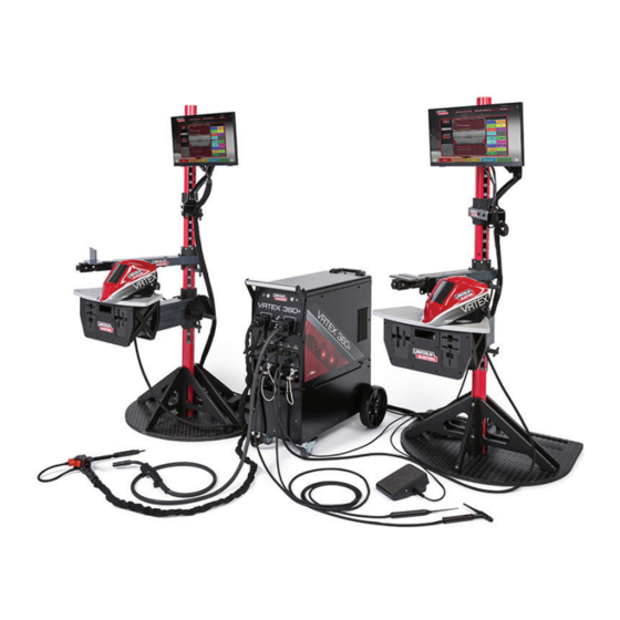
VRTEX 360+, VRTEX 360, VRTEX TRANSPORT INSTALLATION ® ® ® COMPONENT OVERVIEW See Figure 3 for locations of VRTEX 360+ system components. 1. Post 2. Touchscreen Monitor 3. VRTEX Machine 4. Swingarm 5. Table 6. Stand Assembly 7. VR SMAW Device 8. - Page 16 VRTEX 360+, VRTEX 360, VRTEX TRANSPORT INSTALLATION ® ® ® See Figure 4 for locations of VRTEX 360 system components. 1. Post 2. Touchscreen Monitor 3. Helmet 4. Swingarm 5. VRTEX Machine 6. Table 7. Stand Assembly 8. GTAW Filler 9.
- Page 17 VRTEX 360+, VRTEX 360, VRTEX TRANSPORT INSTALLATION ® ® ® See Figure 5 for locations of VRTEX Transport system components. 1. Coupon Stand 2. Touchscreen Monitor 3. Helmet 4. Coupons 5. GTAW Filler VR GTAW/SMAW/GMAW Combo Device 6. Foot Amptrol 7.
-
Page 18: Hardware Specifics
VRTEX 360+, VRTEX 360, VRTEX TRANSPORT INSTALLATION ® ® ® HARDWARE SPECIFICS Figure 7 – VR SMAW device VR GMAW/FCAW GUN The VR gun has a trigger that is used during the simulation of GMAW and FCAW processes to initiate and maintain the simulated welding arc. - Page 19 VRTEX 360+, VRTEX 360, VRTEX TRANSPORT INSTALLATION ® ® ® UNIGUN DEVICE - VRTEX TRANSPORT ONLY FORE / AFT ADJUSTMENT: Adjusts the distance between the FMD and the front of the helmet. To adjust, loosen the outside The Unigun device contains a swappable head to allow switching tension knobs and slide forward or back to desired position and between GMAW, GTAW and SMAW.
- Page 20 Figure 15 – Coupon insertion / removal The coupons along with all VR devices have been factory calibrated by The Lincoln Electric Company. STAND ASSEMBLY The stand is comprised of the post, arm (connected to the machine), table, three pins, base and two weights.
-
Page 21: Hardware Uncrating
VRTEX 360+, VRTEX 360, VRTEX TRANSPORT INSTALLATION ® ® ® Figure 16 – Swing arm rotation 3. Using a utility knife, carefully remove the three plastic bands securing the machine to the skid. See Figure 18. Figure 18 – Plastic bands PLASTIC BANDS 4. -
Page 22: Setup Procedure
VRTEX 360+, VRTEX 360, VRTEX TRANSPORT INSTALLATION ® ® ® SETUP PROCEDURE 6. Using a utility knife, carefully remove the two plastic bands securing the shipping crate to the skid. See Figure 21. 7. Carefully lift the lid off of the shipping crate. See Figure 21. Figure 21 –... - Page 23 VRTEX 360+, VRTEX 360, VRTEX TRANSPORT INSTALLATION ® ® ® Figure 25 – Lower pole section installation 11. Carefully position the top pole onto the lower pole and align the position numbers. See Figure 28. LOWER POLE Figure 28 – Top pole section installation SECTION TOP STAND BASE SCREW...
- Page 24 VRTEX 360+, VRTEX 360, VRTEX TRANSPORT INSTALLATION ® ® ® 18. Connect the coupon arm amphenol to the rear of the machine. 23. Connect the helmet USB, DVI and amphenol to the front of the See Figure 30. machine. See Figure 33. Figure 33 –...
-
Page 25: Device Labels
VRTEX 360+, VRTEX 360, VRTEX TRANSPORT INSTALLATION ® ® ® Figure 36 – Coupon placement DEVICE LABELS The devices for each VRTEX machine are calibrated for optimal performance. It is not recommended to swap a device between machines because the device may not appear properly in the virtual environment. -
Page 26: Operation
LICENSE AGREEMENT The License Agreement is an agreement to the terms and conditions on which Lincoln Electric grants to the business entity registered with Lincoln on the purchase of the Software (“Software Licensee”), a non-exclusive license to use the Software and Documentation accompanying this license on the VRTEX Virtual Reality Welding Trainer. -
Page 27: User Mode
VRTEX 360+, VRTEX 360, VRTEX TRANSPORT OPERATION (USER MODE) ® ® ® USER MODE LOGIN SCREEN SYSTEM SETUP INFORMATION OVERVIEW This page allows the user to: (See Figure 41) When setting up the virtual equipment, the user must set the welding parameters (e.g. -
Page 28: Coupon Configuration Selection Screen
VRTEX 360+, VRTEX 360, VRTEX TRANSPORT OPERATION (USER MODE) ® ® ® PROCESS SELECTION 1. USB Indicator The circular USB icon in the upper right corner of the screen indicates SCREEN the presence of a USB memory stick in the front of the machine. Translucent: no USB stick connected, Green: USB connected and ready, RED: writing data (do not remove). -
Page 29: Environment Screen
VRTEX 360+, VRTEX 360, VRTEX TRANSPORT OPERATION (USER MODE) ® ® ® Figure 46 – Table setup & device status screen Figure 48 – VR coupon (unlocked position) (showing SMAW device needed but not connected) ENVIRONMENT SCREEN Figure 47 – Table setup & device status screen (showing all needed devices are connected) OVERVIEW The VRTEX comes pre-configured with a number of different virtual... -
Page 30: Gas Setup Screen
VRTEX 360+, VRTEX 360, VRTEX TRANSPORT OPERATION (USER MODE) ® ® ® GAS SETUP SCREEN Figure 51 – Polarity selector screen OVERVIEW On this screen, the user selects the gas mixture and gas flow rate. See Figure 50. The correct gas mixture and flow rate must be entered according to the tolerance editor. -
Page 31: Virtual Welding Overview
VRTEX 360+, VRTEX 360, VRTEX TRANSPORT OPERATION (USER MODE) ® ® ® VIRTUAL WELDING VISUAL CUES OVERVIEW Visual cues are aids to help users learn faster. The travel speed, CTWD, arc length and travel/work angle cues indicate whether the user is within the tolerances set in the tolerances editor. Generally, While a user is welding, observers can see the welder’s view, Live these cues are color coded as well as symbolic. -
Page 32: Gtaw Cues
VRTEX 360+, VRTEX 360, VRTEX TRANSPORT OPERATION (USER MODE) ® ® ® The Travel/Work Angle cue can be used with the SMAW, GMAW The Weave cue can be used to space the weave so the outer ring or FCAW processes. See Figure 57. The goal of this cue is to center is green (good weave spacing), set the width of the weave so line is the circle in the cross hair and keep the color green. - Page 33 VRTEX 360+, VRTEX 360, VRTEX TRANSPORT OPERATION (USER MODE) ® ® ® Figure 62 – Filler movement Figure 64 – Postflow AMPERAGE NEW COUPON 1. The footpedal location matches the real life movement of the Selecting the blue new coupon menu icon replaces the current amperage controller.
-
Page 34: Laser Screen
VRTEX 360+, VRTEX 360, VRTEX TRANSPORT OPERATION (USER MODE) ® ® ® TECHNIQUE PARAMETERS END PASS When the user selects the green “End Pass” menu icon, the pass is scored, a snapshot of the weld is taken and the percentages of the weld containing discontinuities are calculated. -
Page 35: Pass Number
VRTEX 360+, VRTEX 360, VRTEX TRANSPORT OPERATION (USER MODE) ® ® ® Position is the user’s ideal weld root location. This location Travel Angle is the angle between the electrode and the workpiece in the direction of travel. See Figure 70. The upper right area of the can change with each pass. -
Page 36: Bead Render
VRTEX 360+, VRTEX 360, VRTEX TRANSPORT OPERATION (USER MODE) ® ® ® BEAD RENDER SCORE An image of the completed pass appears in the middle of the screen. On the upper left of the screen, a score for each parameter is calculated. -
Page 37: Instructor Mode
VRTEX 360+, VRTEX 360, VRTEX TRANSPORT OPERATION (INSTRUCTOR MODE) ® ® ® Figure 75 – Instructors mode screen INSTRUCTOR MODE AND ADMIN ACCESS TO ENTER INSTRUCTOR MODE 1. Touch the “Key” icon located in the lower left corner of the screen. See Figure 73. -
Page 38: Weldometer
VRTEX 360+, VRTEX 360, VRTEX TRANSPORT OPERATION (INSTRUCTOR MODE) ® ® ® WELDOMETER RESET TRIP Selecting Reset Trip zeroes out all items in the trip column. This allows an instructor to track VR material savings over a certain time period. OVERVIEW SAVE TO FILE The Weldometer tracks virtual consumables, arc time, base material... -
Page 39: Tolerance Editor
VRTEX 360+, VRTEX 360, VRTEX TRANSPORT OPERATION (INSTRUCTOR MODE) ® ® ® TOLERANCE EDITOR CHOOSE TOLERANCE SETUP Displays the list of all tolerance settings currently stored on the unit. All units ship with default settings. If the user creates multiple OVERVIEW tolerance files, the file in use is selected by using the red arrow icons. - Page 40 VRTEX 360+, VRTEX 360, VRTEX TRANSPORT OPERATION (INSTRUCTOR MODE) ® ® ® CUSTOMIZE TOLERANCE LEVELS 10. The equipment settings screen allows for the modification of the following welding parameters (See Figure 80): The following steps describe the procedure to change tolerances for •...
- Page 41 VRTEX 360+, VRTEX 360, VRTEX TRANSPORT OPERATION (INSTRUCTOR MODE) ® ® ® 12. The welding technique parameters screen allows the modification 13. The pattern & aim screen allows the user to change the type of of (See Figure 82): pattern being used (stringer, box weave, straight weave, whip, triangle weave) and the position of the root of the weld.
-
Page 42: Scoring Modules
VRTEX 360+, VRTEX 360, VRTEX TRANSPORT OPERATION (INSTRUCTOR MODE) ® ® ® SCORING MODULES 14. The whip & travel screen allows for the modification of technique parameters relating to the whipping welding technique and travel speed including (See Figure 85): •... -
Page 43: Options
VRTEX 360+, VRTEX 360, VRTEX TRANSPORT OPERATION (INSTRUCTOR MODE) ® ® ® SOFTWARE Selecting this option loads a newer version of the software if one is available on a USB inserted in the front of the machine. Updating to a different version may shut down or restart the system. -
Page 44: Additional Features
VRTEX 360+, VRTEX 360, VRTEX TRANSPORT OPERATION ® ® ® ADDITIONAL FEATURES SELECTING SAMPLES TO BEND Select the A or B sample to bend. Figure 92 – Sample A BEND TEST Many welding codes require bend tests as part of the testing required to qualify welders according to welding procedures specifications (WPS’s). - Page 45 VRTEX 360+, VRTEX 360, VRTEX TRANSPORT OPERATION ® ® ® SELECTING ROOT OR FACE Figure 97 – Completed bend test Select the direction of the bend to the ROOT or FACE. Once the desired sample is chosen, press the green BEND icon to begin the bend test.
- Page 46 VRTEX 360+, VRTEX 360, VRTEX TRANSPORT OPERATION ® ® ® THE CERTIFICATE STAINLESS STEEL WELDING SIMULATION The BEND TEST CERTIFICATE is located in the STUDENT REPORT, The Stainless GMAW feature in your VRTEX allows the system to which can be saved and accessed if there is a USB memory device simulate the look, sound, discontinuities, equipment settings and in the USB slot on the front of the VRTEX while performing the virtual Theory definitions for Stainless GMAW.
- Page 47 VRTEX 360+, VRTEX 360, VRTEX TRANSPORT OPERATION ® ® ® LEARNING LEVELS SELECTING A LEARNING LEVEL The Learning Levels, or Tolerance Level, feature in your VRTEX Once Tolerance has been selected, toggle between the different provides 3 skill levels (Entry Level, Intermediate and Advanced) for Learning Levels.
- Page 48 VRTEX 360+, VRTEX 360, VRTEX TRANSPORT OPERATION ® ® ® Figure 108 SELECTING A COUPON FOR RESTARTS The general set up is the same as setting up for the other joints. The user signs in on the “Login” screen and presses the green continue button.
-
Page 49: Cleaning & Maintenance
VRTEX 360+, VRTEX 360, VRTEX TRANSPORT MAINTENANCE ® ® ® CLEANING & BATTERY The backup batteries (two for each computer unit) are located MAINTENANCE behind the access panel on the rear of the machine. See Figures 110 and 111. The “AA” backup batteries can be accessed by using a T-30 torx nutdriver to remove the two screws and the panel. -
Page 50: Troubleshooting
HOW TO USE TROUBLESHOOTING GUIDE WARNING Service and Repair should only be performed by Lincoln Electric Factory Trained Personnel. Unauthorized repairs per- formed on this equipment may result in danger to the technician and machine operator and will invalidate your factory warranty. -
Page 51: Troubleshooting Guide
VRTEX 360+, VRTEX 360, VRTEX TRANSPORT TROUBLESHOOTING ® ® ® TROUBLESHOOTING GUIDE Observe Safety Guidelines detailed in the beginning of this manual. PROBLEMS POSSIBLE AREAS OF RECOMMENDED (SYMPTOMS) MISADJUSTMENT(S) COURSE OF ACTION There is jitter, shake or wobble in the The helmet is too far from the work piece. - Page 52 VRTEX 360+, VRTEX 360, VRTEX TRANSPORT TROUBLESHOOTING ® ® ® TROUBLESHOOTING GUIDE Observe Safety Guidelines detailed in the beginning of this manual. PROBLEMS POSSIBLE AREAS OF RECOMMENDED (SYMPTOMS) MISADJUSTMENT(S) COURSE OF ACTION Previous weld pass data is not accessible “End Pass” must be activated before Use the touch screen to go to pass number on the LASER screen.
-
Page 53: Dimensions
VRTEX 360+, VRTEX 360, VRTEX TRANSPORT DIAGRAMS ® ® ® Figure 112 – Dimensions 38.5 13.8 34.5 19.1... -
Page 54: Wiring Diagrams
VRTEX 360+, VRTEX 360, VRTEX TRANSPORT DIAGRAMS ® ® ® Figure 113 – Wiring diagram... - Page 55 VRTEX 360+, VRTEX 360, VRTEX TRANSPORT DIAGRAMS ® ® ® Figure 114 – Wiring diagram...
- Page 56 VRTEX 360+, VRTEX 360, VRTEX TRANSPORT DIAGRAMS ® ® ® Figure 115 – Wiring diagram PH.2...
-
Page 57: Wiring Diagrams
VRTEX 360+, VRTEX 360, VRTEX TRANSPORT DIAGRAMS ® ® ® Figure 116 – Wiring diagram... - Page 58 Lincoln Electric for advice or information about their use of our products. We respond to our customers based on the best information in our possession at that time. Lincoln Electric is not in a position to warrant or guarantee such advice and assumes no liability, with respect to such information or advice.
Need help?
Do you have a question about the VRTEX 360+ and is the answer not in the manual?
Questions and answers