Table of Contents
Advertisement
RETURN TO MAIN MENU
IM592
®
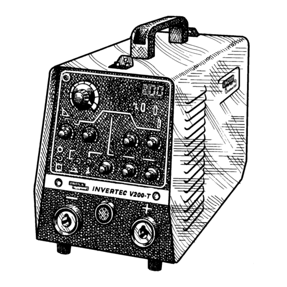
INVERTEC V200-T
November, 1999
10463
For use with machines having Code Numbers:
Safety Depends on You
Lincoln arc welding and cutting
equipment is designed and built
with safety in mind. However, your
overall safety can be increased by
proper installation ... and thought-
ful operation on your part. DO
NOT INSTALL, OPERATE OR
REPAIR THIS EQUIPMENT
WITHOUT
READING
THIS
MANUAL AND THE SAFETY
PRECAUTIONS CONTAINED
THROUGHOUT. And, most
importantly, think before you act
and be careful.
OPERATOR'S MANUAL
• World's Leader in Welding and Cutting Products •
• Sales and Service through Subsidiaries and Distributors Worldwide •
Cleveland, Ohio 44117-1199 U.S.A. TEL: 216.481.8100 FAX: 216.486.1751 WEB SITE: www.lincolnelectric.com
Advertisement
Table of Contents

Related Manuals for Lincoln Electric INVERTEC V200-T


Summary of Contents for Lincoln Electric INVERTEC V200-T
- Page 1 RETURN TO MAIN MENU IM592 ® INVERTEC V200-T November, 1999 10463 For use with machines having Code Numbers: Safety Depends on You Lincoln arc welding and cutting equipment is designed and built with safety in mind. However, your overall safety can be increased by proper installation ...
-
Page 2: California Proposition 65 Warnings
351040, Miami, Florida 33135 or CSA Standard W117.2-1974. A Free copy of “Arc Welding Safety” booklet E205 is available from the Lincoln Electric Company, 22801 St. Clair Avenue, Cleveland, Ohio 44117-1199. BE SURE THAT ALL INSTALLATION, OPERATION, MAINTENANCE AND REPAIR PROCEDURES ARE PERFORMED ONLY BY QUALIFIED INDIVIDUALS. -
Page 3: Electric Shock Can Kill
ELECTRIC SHOCK can kill. 3.a. The electrode and work (or ground) circuits are electrically “hot” when the welder is on. Do not touch these “hot” parts with your bare skin or wet clothing. Wear dry, hole-free gloves to insulate hands. - Page 4 WELDING SPARKS can cause fire or explosion. 6.a. Remove fire hazards from the welding area. If this is not possible, cover them to prevent the welding sparks from starting a fire. Remember that welding sparks and hot materials from welding can easily go through small cracks and openings to adjacent areas.
- Page 5 PRÉCAUTIONS DE SÛRETÉ Pour votre propre protection lire et observer toutes les instructions et les précautions de sûreté specifiques qui parraissent dans ce manuel aussi bien que les précautions de sûreté générales suiv- antes: Sûreté Pour Soudage A L’Arc 1. Protegez-vous contre la secousse électrique: a.
- Page 6 This statement appears where the information must be followed to avoid minor personal injury or damage to this equipment. for selecting a QUALITY product by Lincoln Electric. We want you to take pride in operating this Lincoln Electric Company product •••...
-
Page 7: Table Of Contents
TABLE OF CONTENTS Installation...Section A Technical Specifications ...A-1 Select Suitable Location ...A-2 Stacking...A-2 Lifting and Moving ...A-2 Tilting ...A-2 Environmental Rating ...A-2 Machine Grounding and High Frequency Interference Protection ...A-2 Input Connections ...A-3 Input Fuse and Supply Wire ...A-3 Output Connections...A-4 Operation...Section B General Description...B-1 Operational Features...B-1... -
Page 8: Installation
Size Nameplate 10 (5.2 mm 2 ) 12 (4 mm 2 ) PHYSICAL DIMENSIONS Width 7.48 in. 190 mm STORAGE TEMPERATURE INVERTEC V200-T Code Number 10463 Volts at Rated Amperes Type of Output Type 75°C Copper Ground Wire in Conduit... -
Page 9: Select Suitable Location
STACKING The Invertec V200-T cannot be stacked. LIFTING AND MOVING The Invertec V200-T has a lift handle on the top of the case and also comes with a lift-carrying strap for con- vience. TILTING Place the machine directly on a secure, level surface. -
Page 10: Input Connections
Follow the power cord connection instructions. Incorrect connection may result in equipment damage. The Invertec V200-T is internally connected for a 460 volt input. The input switch has a lock pin which restricts movement for 460 selection only. See figure A.1. -
Page 11: Output And Gas Connection For Tig Welding
Turn the Power Switch “OFF”. Connect the torch cable quick connect plug into the DC- Output Receptacle on the front of the welder and turn it clockwise until it is tight. This is a quick connect terminal and also provides the gas connection cable plugs is for the shielding gas to the torch. -
Page 12: Shielding Gas Connection
(usually argon). Connect the cylinder of gas with the pressure regulator and flow gage. Install the gas hose between the regulator and gas inlet (located on the low left rear of the welder). The gas inlet has a 5/16-18 right hand female thread; CGA #032. BOOT... -
Page 13: Safety Instructions
WELDING CAPABILITY The Invertec V200-T is rated at 200 amps, 28 volts, at 20% duty cycle on a ten minute basis. It is capable of higher duty cycles at lower output currents. It is capa- ble of 120 amps, 25 volts at at 100% duty cycle. -
Page 14: Controls And Settings
Remote Control Connector - This receptacle will accept a Lincoln Foot Amptrol, Hand Amptrol or Arc Start Switch. See the ACCESSORIES section for available options. INVERTEC V200-T Digital Display Gas Available LED Power LED Slope Down Time Pot. - Page 15 LED will go off. Any activity on the output will immediately “Wake” the inverter up, the LED will come back on and normal operation will resume. INVERTEC V200-T...
-
Page 16: Operating Steps
When the welder is in the stick mode a remote control has no effect and is not used. It is important to note that, in some cases, the tung- sten will not start an arc at the minimum current because the tungsten may be too large or cold. -
Page 17: Welding In Stick Mode
Blue Max Stainless Red Baron Stainless Mild steel procedures are based on recommended procedures listed in C2.10 8/94 and the maximum rating of the Invertec V200-T Jet-LH MR procedures are based on Jet-LH 78 MR Blue Max procedures are based on C6.1 6/95... -
Page 18: Explanation Of 2 Step And 4 Step Modes
The pulse frequency, duration and amplitude may be adjusted by means of the respective potentiometers. TORCH SWITCH WELDING CURRENT WITHOUT RESTART WITH RESTART TORCH SWITCH WELDING CURRENT INVERTEC V200-T (As shipped no jumper) CRATER CURRENT... -
Page 19: Optional Accessories
When using the Arc Start Switch set the Output Control to the “LOCAL” position. Magnum® LA-9 and LA-17/LA-17V TIG Torches - The following standard Magnum® TIG torches with one-piece cable may be used with the Invertec V200-T. • K859-1 LA-9 12.5 ft medium back cap •... -
Page 20: Maintenance
Replace the blown fuse with a new 0.5A 500V slowblow fuse. NOTE: If the fuse blows again after power is restored, the cause could be an internal breakdown in the power unit. In this case, take the unit to an authorized Lincoln Field Service Shop. INVERTEC V200-T... -
Page 21: Troubleshooting
HOW TO USE TROUBLESHOOTING GUIDE Service and Repair should only be performed by Lincoln Electric Factory Trained Personnel. Unauthorized repairs performed on this equipment may result in danger to the technician and machine operator and will invalidate your factory warranty. For your safety and to avoid Electrical Shock, please observe all safety notes and precautions detailed throughout this manual. - Page 22 2. Install new fuses and reapply power. If fuses open again, con- sult a Lincoln Authorized Field Service Facility. CAUTION INVERTEC V200-T RECOMMENDED COURSE OF ACTION If all recommended possible areas of misadjustment have been checked and the problem persists, Contact your local Lincoln Authorized Field Service Facility.
- Page 23 DIAGRAMS...
-
Page 24: Parts List
This parts list is provided as an informative guide only. This information was accurate at the time of printing. However, since these pages are regularly updated in Lincoln Electric’s official Parts Book (BK-34), always check with your Lincoln parts supplier for the latest parts information. - Page 25 P-308-A.1 P-308-A.1 INVERTEC V-200-T For Codes: 10463 Do Not use this Parts List for a machine if its code number is not listed. Contact the Service Department for any code numbers not listed. Use the Illustration of Sub-Assemblies page and the table below to determine which sub assembly page and col- umn the desired part is located on for your particular code machine.
- Page 26 P-308-C P-308-C General Assembly 11-4-98 INVERTEC V-200-T...
- Page 27 Aluminum Cover (Red) Rear Panel Front Panel Output Choke High Frequency Filter PCB Bolt Name Plate Lincoln Electric Decal Input Connection Decal Rating Plate Gas Input Decal 1 Year Warranty Decal Electric Shock Warning Decal Grounding Warning Decal Fuse, 0.5A/500 Volt Slow Blow...
- Page 28 NOTES INVERTEC V-200-T...
-
Page 29: Basic Course
Address: Telephone: _______________________________________________ |_|_| |_|_| Exp Date Month BOOK DIVISION, The Lincoln Electric Company, 22801 St. Clair Avenue, Cleveland, Ohio 44117-1199 for fastest service, FAX this completed form to: 216-361-5901 Telephone: 216-383-2211 or, Titles: Price New Lessons in Arc Welding $5.00... - Page 30 WARNING Spanish AVISO DE PRECAUCION French ATTENTION German WARNUNG Portuguese ATENÇÃO Japanese Chinese Korean Arabic READ AND UNDERSTAND THE MANUFACTURER’S INSTRUCTION FOR THIS EQUIPMENT AND THE CONSUMABLES TO BE USED AND FOLLOW YOUR EMPLOYER’S SAFETY PRACTICES. SE RECOMIENDA LEER Y ENTENDER LAS INSTRUCCIONES DEL FABRICANTE PARA EL USO DE ESTE EQUIPO Y LOS CONSUMIBLES QUE VA A UTILIZAR, SIGA LAS MEDIDAS DE SEGURIDAD DE SU SUPERVISOR.
- Page 31 Keep your head out of fumes. Turn power off before servicing. Use ventilation or exhaust to remove fumes from breathing zone. Los humos fuera de la zona de res- Desconectar el cable de ali- piración. mentación de poder de la máquina Mantenga la cabeza fuera de los antes de iniciar cualquier servicio.
- Page 32 • World's Leader in Welding and Cutting Products • • Sales and Service through Subsidiaries and Distributors Worldwide • Cleveland, Ohio 44117-1199 U.S.A. TEL: 216.481.8100 FAX: 216.486.1751 WEB SITE: www.lincolnelectric.com...
Need help?
Do you have a question about the INVERTEC V200-T and is the answer not in the manual?
Questions and answers