Lincoln Electric VRTEX 360 Operator's Manual
Hide thumbs
Also See for VRTEX 360:
- Service manual (171 pages) ,
- Operator's manual (56 pages) ,
- Service manual (171 pages)

Related Manuals for Lincoln Electric VRTEX 360


Summary of Contents for Lincoln Electric VRTEX 360
- Page 1 IM2052 09/2017 Rev01 ® VRTEX OPERATOR’S MANUAL ENGLISH LINCOLN ELECTRIC EUROPE S.L ° c/o Balmes, 89 – 8 2a, 08008 Barcelona, Spain www.lincolnelectric.eu...
- Page 2 THE LINCOLN ELECTRIC COMPANY EC DECLARATION OF CONFORMITY Manufacturer and technical documentation holder: The Lincoln Electric Company Address: 22801 St. Clair Ave. Cleveland Ohio 44117-1199 USA EC Company: Lincoln Electric Europe S.L. Address: c/o Balmes, 89 - 8 08008 Barcelona...
-
Page 3: Table Of Contents
12/05 THANKS! For having chosen the QUALITY of the Lincoln Electric products. Please Examine Package and Equipment for Damage. Claims for material damaged in shipment must be notified immediately to the dealer. For future reference record in the table below your equipment identification information. Model Name, Code &... -
Page 4: Technical Specifications
Technical Specifications ™ VRTEX 360 - VIRTUAL REALITY WELDING TRAINER INPUT INPUT VOLTAGE INPUT CURRENT MAKE/MODEL DESCRIPTION ±10% (MAX.) K3962-1 Standard Frequency 115-230 VAC (50-60 HZ) 4A-2A Single Phase K3962-2 Alternate Frequency 115-230 VAC (50-60 HZ) 4A-2A Single Phase WARNING THIS PRODUCT INCORPORATES A PROTECTIVE EARTH IN THE AC POWER CORD. -
Page 5: Electromagnetic Compatibility (Emc)
Lincoln Electric. Before installing the machine, the operator must check the work area for any devices that may malfunction because of electromagnetic disturbances. -
Page 6: Safety
Failure to follow the instructions in this manual could cause serious personal injury, loss of life, or damage to this equipment. Read and understand the following explanations of the warning symbols. Lincoln Electric is not responsible for damages caused by improper installation, improper care or abnormal operation. -
Page 7: Installation
WELDING SPARKS CAN CAUSE FIRE OR EXPLOSION: Remove fire hazards from the welding area and have a fire extinguisher readily available. Welding sparks and hot materials from the welding process can easily go through small cracks and openings to adjacent areas. Do not weld on any tanks, drums, containers, or material until the proper steps have been taken to insure that no flammable or toxic vapors will be present. - Page 8 Read this entire section before installation or operation WARNING of the machine. Lift only with equipment of adequate lifting capacity. Be sure machine is stable when Location and Environment lifting. Do not operate machine while suspended when lifting. The machine will not operate in harsh environments. It is important that simple preventative measures are FALLING EQUIPMENT can cause injury.
- Page 9 frequency TIG machines and power sources. DESIGN FEATURES Having these types of objects in the area can cause interference and result in increased jitter and/or distortion in the motion tracking. HARDWARE OVERVIEW: ® For best results, do not install VRTEX Virtual Welding Machine, including: machine in the welding lab.
- Page 10 NOTE: Do not remove rear panel. DO NOT REMOVE REMOVE REAR FRONT PANEL PANELS STEP (2) Monitor Using the 3/8” wrench, remove the two screws from the rear base securing the unit to the 3/8” BOLTS wooden crate. FRONT (upper) FRONT (lower) Remove the six 3/8”...
- Page 11 Insert one of the pins into the post at the #6 loca- tion. From the top, slide the table onto the post letting it Screws Table rest on the pin inserted in previous step. Insert the second pin into the post at the #13 position.
- Page 12 2. Remove the cable ties from monitor cables secured to the monitor mounting post. 2. The weld simulation can be displayed on an external 3. Use a Phillips-head screwdriver to carefully mount monitor or projector by using the VGA output on the the monitor onto the mounting post bracket.
-
Page 13: Operation
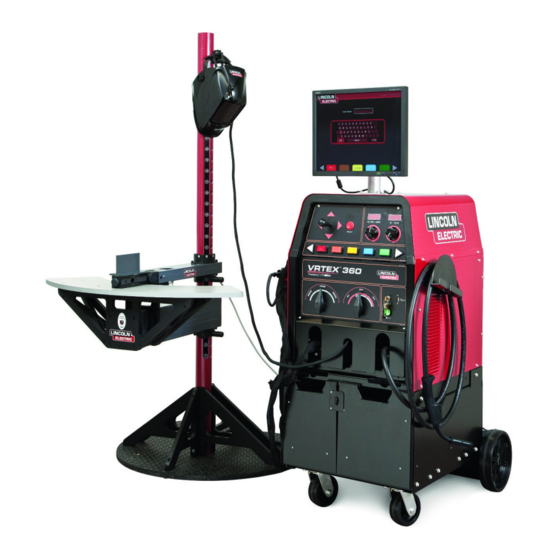
Operation PRODUCT DESCRIPTION The VRTEX® 360 is a virtual reality arc welding training machine only and NOT a real arc welding machine. Please be aware of all standard safety practices associated with welding. Some standard warnings are included in this manual. If the equipment is used in a manner not specified by the manufacturer, the protection provided to the equipment and user may be impaired. - Page 14 12. The red select button accepts (enters) the data USER INTERFACE OVERVIEW displayed or highlighted on the monitor. 13. VR GMAW/FCAW gun holder should be used to ® The VRTEX 360 is a virtual reality arc welding trainer. store the VR GMAW/FCAW gun when not in use. This computer based training system is an educational tool designed to allow students to practice their welding 14.
- Page 15 HARDWARE SPECIFICS: WARNING Do not try to strike the arc with excessive force, as the arc start is distance based. Excessive force may result in VR GMAW/FCAW GUN damage to the VR SMAW device. The VR gun has a trigger that is used during the simulation of GMAW and FCAW processes to initiate The angle of the rod can be changed by squeezing the and maintain the simulated welding arc.
- Page 16 Helmet HEAD SIZE ADJUSTMENT: HEADGEAR TIGHTNESS is adjusted by pushing in the Ratchet Knob and turning EAR BUDS to adjust for the desired head size. This knob is located The ear buds at the back of the helmet. HEADGEAR CROWN are close to ADJUSTMENT is made by adjusting for comfort and the ears so...
- Page 17 The coupons along with the VR SMAW device and VR WARNING GMAW/FCAW gun have been factory calibrated at Do not use excessive force when inserting and removing Lincoln Electric. coupons into the arm.. Stand SWING ARM ROTATION The stand is comprised of the post, arm, table, Three pins, base and two weights.
- Page 18 Powering Up Your System: Login After you have set up the hardware and have Joint configuration selection become familiar with the user controls, you will be Process selection ready to use your system. Stand set up Plug the power cord into a standard outlet.
- Page 19 Press the red select button to accept. Login Screen: Press the orange language menu button again to exit the Overview language menu. The system stores the language This page allows the user to: selection and will automatically start up in the same language the next time.
- Page 20 7. Theory Button Screen JOINT CONFIGURATION SELECTION SCREEN Overview The THEORY button has been implemented to assist users with additional content, images and information related to the area of the application where you are working. This information can be accessed by selecting ®...
- Page 21 TABLE B.2 GMAW SMAW FCAW Position Thickness (in) Thickness (mm) Short Arc Axial Spray Pulse STT E7018 E6010 E6013 Shielded Flat 10 GA. 3F up 3F down 10 GA. 10 GA. 2" XXS 6" Sch 40 2" XXS 6" Sch 40 2"...
- Page 22 STAND SET-UP SCREEN SWING ARM ROTATION POSITION A POSITION C POSITION B Coupon Insertion TABLE ROTATION Insert one of the VR coupons into the desired position in the physical VR stand. Make sure the coupon is fully seated into the track and then lock the coupon in place by pushing in the knob at the end of the arm.
- Page 23 PIN POSITIONS 18 A STAND SET-UP SCREEN OVERLAY Back Selecting Back takes the user to the previous screen. Environment Screen: Overview PIN POSITION ® The VRTEX 360 comes preconfigured with a number of different virtual welding environments. To select an Note: If the table height indicator in the software cannot environment, the user moves the joystick left or right and be moved to the pin height indicated on the post,...
- Page 24 GAS SET-UP SCREEN Polarity Selector Change the polarity by rotating the polarity selector switch. The user can select the following: • AC • DC+ • DC- If default tolerances are being used, refer to the Default Weld Process Settings included in this manual.
- Page 25 Menu Clean removes the weld slag. Trim cuts back the VR GMAW or VR FCAW wire. Quench simulates quickly Selecting Logout brings the user back to the login cooling the metal. New Stick extends the rod stick out to screen, with the user’s name removed. a fixed length on the VR SMAW device to simulate replacing the consumed rod.
- Page 26 CTWD (Contact Tip to Work Distance) The Whip cue can be used with the E6010 VR SMAW process. This cue helps the student use correct spacing between whipping motions, puddle time and whip time. The Arc Length cue is similar to the CTWD cue but Correct whipping technique is indicated by a green represents arc length distance for the VR SMAW outter ring (spacing) with a green center (puddle and...
- Page 27 WEAVE LASER SCREEN (Live Action Student Evaluation Report) Overview This screen summarizes the student’s welding performance. Detailed information about the student’s welding technique for each pass are displayed on this screen. LASER SCREEN (GOOD WELD) New Coupon Pressing the blue new coupon menu button instantly replaces the current coupon with a fresh, unwelded coupon.
- Page 28 LASER SCREEN (GRAPH, DEFECTS, DISCONTINUITIES, ETC.) WELD TECHNIQUE GRAPH DISCONTINUITY INDICATOR TECHNIQUE PARAMETERS The upper left area of the screen shows the technique parameters being tracked and the graph of these parameters is located to the right. When the user welds, each parameter is graphed using a line that is of the same color as the technique parameter box.
- Page 29 Position is the user’s ideal weld root location. This location can change with each pass. When weaving, the Travel Angle is the angle between the electrode and the ideal location is considered the centerline of the weave. workpiece in the direction of travel. The upper right area of the screen displays if the user should be pushing or Contact Tip to Work Distance (CTWD) (for VR GMAW dragging.
- Page 30 Excess Spatter Travel Speed is how fast the electrode is traveling in Melt Through/Blow Through respect to the workpiece. Dime Spacing is the distance from one solidified weld puddle to the next. (whip technique only) Whip Time is the time the user is in the whipping motion, or not dwelling in the weld puddle.
- Page 31 0 will mute the sound, while a volume of 10 is ® the loudest. For more information on the VRTEX 360 Upgrade Program, please contact your Lincoln Electric sales Update representative or the Lincoln Electric Automation Division. TEL: 1-216-481-8100, Ask for the Overview Automation Division.
- Page 32 usage and arc time over a “trip” (since last reset) and ® Weldometer over the VR system’s lifetime. Overview Arc Time keeps track of the amount of time (hours:min:seconds) students have a virtual arc struck ® The Weldometer tracks virtual consumables, base with each process.
- Page 33 Base Metal tracks how many virtual coupons have been used and their cumulative weight. Note that plate 3/8” TOLERANCES includes groove joints as well as T-joints, while plate 10GA. and 1/4" includes both T-joints and practice plates. Gas tracks how much virtual gas was used. Consumables tracks the cumulative weight of each type of virtual consumable used.
- Page 34 Pressing Copy makes a copy of the file currently being shown on the choose tolerance setup window. The copy TOLERANCES SELECTED (DEFAULTS) is identified with the same name plus an incremented number after it. Pressing Delete brings up an “are you sure” dialogue. Selecting yes deletes the file currently shown.
- Page 35 Menu Modifying Tolerances Overview Selecting Logout and then yes in the submenu takes The user can modify the tolerance values. This is done the user back to the Login screen. 1) Use the joystick to highlight the equipment setting or Selecting Change Process brings the user back to the parameter to change.
- Page 36 Tolerances Welding Technique Tolerances Equipment Settings Screen Parameters Screen Overview TOLERANCES EQUIPMENT SETTINGS SCREEN This screen allows the modification of: CTWD/Arc Length Work Angle Travel Angle TOLERANCES WELDING TECHNIQUE PARAMETERS Overview This screen allows for the modification of the following welding parameters: ...
- Page 37 Tolerances Pattern and Aim Screen Overview This screen allows the user to change the type of pattern being used (stringer, box weave, straight weave, whip, triangle weave) and the position of the root of the weld. The X and Y values change the location of where the weld bead should be placed.
- Page 38 For more information on Travel Speed ® the VRTEX 360, please contact: The Lincoln Electric Company - Automation Division at 22221 St. Clair WHIP & TRAVEL SPEED SCREEN Avenue, Cleveland, OH 44117-2522, via phone at 1(888) 935-3878 or e-mail at: vrtex@lincolnelectric.com.
- Page 39 Selecting Root or Face: Use the joystick to highlight and toggle between the ROOT and FACE bend. Once the desired sample is chosen, press the red SELECT button to begin the bend test. ROOT CONTINUE button becomes BEND TEST button upon completion of the weld.
- Page 40 Once the first sample has been bent, use the white The bent sample can also be rotated for further visual NEXT or PREV arrow buttons to select the next tab to inspection by using the joystick. FaceBend visual bend. inspection Passed. GREEN TO BEND FaceBend Visual Passed BEND TEST FAILURE:...
- Page 41 EXITING THE BEND TEST: Failed To exit the bend test application, press the red MENU button and use the joystick to toggle to YES then press the red SELECT button. This will take the user back to the LASER screen. PRESS RED MENU BUTTON TO EXIT Percentages of RootBend Failure ARE YOU SURE PRESS YES RED SELECT BUTTON...
- Page 42 SCORING MODULES: THE CERTIFICATE: Overview: After welding a pass, the user can now see whether The BEND TEST CERTIFICATE is located in the each defect/discontinuity was within acceptable STUDENT REPORT, which can be saved and accessed standards (passed) or not (failed). The acceptable if there is a USB memory device in the USB slot on the ®...
- Page 43 Choose Scoring Module Standards Selects Visual Cues or Action Overview: The Visual Cues and Actions that have been selected by PANNING MODE: the user will now appear as icons on the LASER screen below the Discontinuities window. The icons will remain Overview: ghosted until the user selects the option to use the The panning view function enhances the instructor’s...
- Page 44 .pdf formatted version of the agreement. The License Agreement is an agreement to the terms and conditions on which Lincoln Electric grants to the Once the user has agreed to the terms of the EULA they business entity registered with Lincoln on the purchase can view a pdf copy of the EULA by pressing the white of the Software (“Software Licensee”), a non-exclusive...
- Page 45 “Process Selector” switch located on the face of the Overview: VRTEX® 360 to the GMAW position. Selecting between The Aluminum GMAW feature in your VRTEX 360 Spray and Pulse can be accomplished by moving the allows the system to simulate the look, sound,...
- Page 46 Overview: motion to highlight 100% Argon and press the red The Video Replay feature in your VRTEX 360 provides “Select” button. The next step is to set the gas flow rate. the ability to view your virtual weld video once you have Refer to the WPS to see the recommended flow rate for completed it.
- Page 47 Entry Level Tolerance Selection Overview: The Learning Levels, or Tolerance Level, feature in your VRTEX 360 provides 3 skill levels (Entry Level, Intermediate and Advanced) for students in your welding training program. As the progression of skills and capabilities progress, you can enable different levels to keep students challenged, excited and engaged in learning.
- Page 48 Advanced: Any additional tolerance settings that have been created by the user will also appear in this box. Those tolerance The “Advanced” Learning Level is designed to be the settings can still be accessed and changed as the user most challenging. This level is for the student that has deems necessary.
- Page 49 VRTEX® 360 - Default Weld Process Settings VR Welding WPS # Consumable Type Lincoln Brand Gas Mixture Gas Flow (CFH) Position Mat'l (in) WFS (ipm) or amps Voltage Pol. Process SMAW 1/8" E6010 (3.2 mm) Fleetweld 5P+ Flat 1/4" (6 mm) 90 (±5) 2,3,4 SMAW...
- Page 50 You can also use a time. Lincoln Electric is not in a position to warrant or lens cloth (e.g., from a camera shop). Paper towels or...
-
Page 51: Weee
WEEE 07/06 Do not dispose of electrical equipment together with normal waste! In observance of European Directive 2012/19/EC on Waste Electrical and Electronic Equipment (WEEE) and its implementation in accordance with national law, electrical equipment that has reached the end of its life must be collected separately and returned to an environmentally compatible recycling facility. -
Page 52: Electrical Schematic
Electrical Schematic K3962 - Series NOTE: this diagram is for reference only. It may not be accurate for all macjines covered by this manual. The specific diagram for a particular code is includedwith the machine. If the diagram is illegible, write to the Service Department for a a replacement.
Need help?
Do you have a question about the VRTEX 360 and is the answer not in the manual?
Questions and answers