
Summary of Contents for B. Braun Aquaboss CCS
- Page 1 Instructions for use Concentrate supply Rev. 2.8 Date 2019-02-04 Software version 1.00...
- Page 2 Notes on operating instructions Rev. 2.8 Date 2019-02-04 Software version 1.00...
- Page 3 If these operating instructions are not followed, B. Braun cannot guarantee safe system operation. B. Braun reserves the right to alter sections of these operating instructions or technical data without prior notice.
- Page 4 ......................... Please include further pages if necessary. You can also include pages you have copied from the operating instructions and improved by adding comments. Please send your suggestions to: B. Braun Avitum AG Schwarzenberger Weg 73-79 34212 Melsungen Germany Fax: +49 (56 61) 75-0 Notes on operating instructions Rev.
- Page 5 Notes on operating instructions The operating instructions contain information regarding the safe use of the system. The user must convince himself of the correct function and proper state of the medical product before put- ting it to use, and heed the operating instructions and other information and maintenance instructions enclosed.
- Page 6 Signs and symbols used in the operating instructions The signal word indicates a high-risk hazard which, if not avoided, will cause death or DANGER severe injury. The signal word indicates a medium-risk hazard which, if not avoided, will cause death or WARNING severe injury.
- Page 7 → Non-adherence to the manufacturer’s maintenance instructions could lead to a functional impact on the system. → An annual safety inspection (STK) is prescribed by B. Braun-authorized experts. Danger of poisoning by released construction materials, and hazard to patients due to WARNING system failure.
- Page 8 EMC information provided in this instruction booklet. Only original parts from B. Braun may be used. B. Braun does not accept any liability for NOTE damage caused by spare parts, consumables or accessories that are not original B. Braun parts.
- Page 9 NOTE → Section 2, page 8-1 and → Section 1, page 3-1. B. Braun does not accept liability for damage caused by the use of other spare parts, accessories and consumables. Portable and mobile HF communication equipment can influence lectrical medical NOTE equipment.
- Page 10 Notes on operating instructions Rev. 2.8 Date 2019-02-04 Software version 1.00...
- Page 11 These operating instructions comprise two sections: Section 1 – Operating Instructions Here you will find subjects important for normal operation of the system. 1. Safety 2. Area of application and intended use 3. Accessories List 4. Use in combination with other equipment 5.
- Page 12 Notes on operating instructions Rev. 2.8 Date 2019-02-04 Software version 1.00...
- Page 13 Notes on operating instructions Rev. 2.8 Date 2019-02-04 Software version 1.00...
-
Page 14: Table Of Contents
Section 1 – Operating Instructions Safety ..................1-1 General safety ....................1-1 Safety during repair, servicing and maintenance ........1-1 1.2.1 Operational safety .................... 1-1 1.2.2 Functional safety ....................1-1 1.2.3 Risks due to non-observance of safety instructions ......... 1-2 1.2.4 Impermissible operating modes ............... - Page 15 Modes of operation ..................6-3 6.2.1 System OFF ..................... 6-3 6.2.2 Manual mode ....................6-3 6.2.3 Automatic mode ....................6-3 Venting ......................6-3 Economy mode....................6-3 Pressure regulation..................6-4 6.5.1 Switch-on monitoring..................6-4 6.5.2 Pump start-up....................6-4 6.5.3 Pressure regulator.................... 6-4 Container replacement ..................
-
Page 16: Safety
→ Switch off the device at the main switch and unplug from the mains. Maintenance and repair work may only be carried out by authorized specialists. Only original parts from B. Braun may be used. B. Braun does not accept any liability for NOTE damage caused by spare parts, consumables or accessories that are not original B. -
Page 17: Risks Due To Non-Observance Of Safety Instructions
When central concentrate systems are used (acid concentrates), examination of the system for the presence of fungi/micro-organisms is recommended once a year. If fungi/micro-organisms are found, B. Braun recommends consultation with the manufacturer to agree further measures. Residual risks Residual risks remain despite the measures taken to avoid such risks. -
Page 18: Area Of Application And Intended Use
Area of application and intended use The operator is responsible for the proper operation of the system. The intended use is the pumping and distribution of liquid acid hemodialysis concentrates. NOTE The Aquaboss Central Concentrate Supply CCS may only be used for the intended purpose and is designed for a lifetime of 10 years. -
Page 19: Contraindications And Side Effects
Contraindications and side effects 2.4.1 Contraindications The CCS may not be used: • at expired expiry date of the connected concentrate container. • in case of unclear chemical or microbiological quality of the concentrate. • if the concentrates to be pumped do not comply with ISO 13958. 2.4.2 Side effects Not known. -
Page 20: Accessories List
Accessories List Pos. Description Item no. Control CCS 2000300 Remote control Control CCS 2000200 Remote control Process visualisation 2000100 Basic licence Hardware extension 1050170 Individual licence CCS 2001060 Bumper guard 9500206 Suction and float lance for 93579 barrel operation ATTENTION The use of other accessories, cables or transformers with the CCS device lead to an increase in jamming and a reduction in noise immunity. - Page 21 Page 3-2 Accessories List Rev. 2.8 Date 2019-02-04 Software version 1.00 Section 1 – Operating Instructions...
-
Page 22: Use In Combination With Other Equipment
DIN EN 11197 (VDE 0750-211), medical supply units. Where in-house production of acid concentrates is carried out, the service life of the couplings used by MPC can be restricted. In this case, B. Braun recommends the use of stainless steel coupling sets made of seawater-proof material. - Page 23 Page 4-2 Use in combination with other equipment Rev. 2.8 Date 2019-02-04 Software version 1.00 Section 1 – Operating Instructions...
-
Page 24: Return And Disposal
Return and disposal In accordance with legislative regulations, B. Braun Avitum AG offers to take back sys- tems it supplies and dispose of these as stipulated by legislation. Electrical medical devices are subject to the Guideline for used electric and electronic appliances 2002/96 dated January 27, 2003, and have to be disposed of in an environ- mentally friendly manner. - Page 25 Page 5-2 Return and disposal Rev. 2.8 Date 2019-02-04 Software version 1.00 Section 1 – Operating Instructions...
-
Page 26: Function And Modes Of Operation
Function and Modes of Operation General 6.1.1 CCS with hydraulic part and supply via pump(s) The concentrate supply system CCS is based on a pressure and quantity-regulated supply of undiluted hemodialysis concentrates (acid concentrates) in a supply line with the intention of supplying hemodialysis equipment with hemodialysis concentrates (acids). -
Page 27: Set-Up / Basic Function
6.1.2 Set-up / Basic Function The structure of a concentrate supply system can be seen in the following sketches: Concentrate 1 Figure 6-1: Flow diagram CCS The concentrate is emptied into the closed pre-filling vessel of the hydraulic part from one of two supply containers per installed concentrate loop (C1.1, C1.2 …... -
Page 28: Turning The System On
6.1.3 Turning the system on The following tests are carried out when the system is turned on: 1. EPROM test 2. RAM test 3. EEPROM test 4. CPU watchdog test 5. Watchdog power unit test 6. Green operation and red fault display light up briefly 6.1.4 CPU watchdog When the CPU watchdog is triggered, device reset occurs (similarly to when the device is switched on) -
Page 29: Pressure Regulation
Pressure regulation 6.5.1 Switch-on monitoring • Switch the pump on. • Pressure must reach at least 0.3 bar within 15 s or reach the reference value if this is smaller than 0.3 bar. If not: switch off the supply line signalise pressure problem 6.5.2 Pump start-up... -
Page 30: Operation
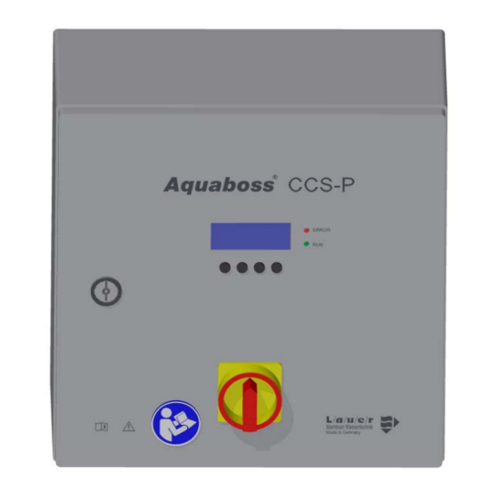
Operation Display and keyboard Figure 7-1: Keyboard with 4-line display 1 Display 2 LED red, Error/Alarm 3 LED green, RUN 4 Enter key F4 5 Setting keys F2, F3 6 Menu key F1 Operation Page 7-1 Rev. 2.8 Date 2019-02-04 Software version 1.00 Section 1 –... - Page 31 Page 7-2 Operation Rev. 2.8 Date 2019-02-04 Software version 1.00 Section 1 – Operating Instructions...
-
Page 32: System Data Parameters
System data parameters A system test is carried out after switch-on. The display lamps light up for 3 seconds. If the power supply is interrupted, the mode of operation last CCS-PX.X hh:mm selected is saved. Lauer Test Display of the system type CCS P x.y. The x stands for the number of concentrates to be pumped, the y for the number of floors. -
Page 33: Langauge, Menu Item 0
Langauge, menu item 0 The menu item 0 indicates the current user language. A different language can be selected using and confirmation through 0 Language the Esc key. To change the display language, the system must be switched on using the main switch (1) and the language selected accordingly under the sub-menu “0”... -
Page 34: Container Reset, Menu Item 3
Container reset, menu item 3 Only the empty containers are displayed. Reset Reset fault message 3 Container Reset C1.1 Reset (only possible when level switch “on”). C1.2 Reset C2.1 Reset C2.2 Reset C3.1 Reset C3.2 Reset Enter Pressure alarm reset, menu item 4 A pressure alarm can be acknowledged after the cause has been eliminated. -
Page 35: System Data, Menu Item 6
Menu item 6 can be seen in all operating modes. It includes the option of changing the system parameters set by the service staff from B. Braun Avitum AG (B. Braun) during commissioning. Changes may only be carried out by staff who have been authorized to do so. - Page 36 Service interval Interval between two routine service checks. System type CCS-Z X.Y 0 to 12 months (0 = -- = off). V XX.XX-XX The software version/save date is displayed by pressing the two middle function keys. System type SW-Date: XX.XX.XXXX Routine check XX months Operating hours of the system...
-
Page 37: System Data Menu 6B Program
8.8.2 System data menu 6B Program When menu 6.B Program is selected, the following screen appears: A 4-digit service code must be entered for the system data to be changed. 6 System data Enter code XXXX Enter Menu 6.1B to 6.6B Pressure 0.10 to 5.00 bar (D = 0.05 bar). -
Page 38: Maintenance Program, Menu Item 7
Maintenance program, menu item 7 Under menu 7, maintenance program, the active elements (pumps, sole- noids) can be replaced under 7.1 Outputs. The digital switching states of 7 Maintenance pgm. the inputs can be regulated under 7.2. 7.1 Outputs 7.2 Inputs 7.3 Venting ... -
Page 39: Maintenance Program, Venting
8.9.3 Maintenance program, venting The menu can only be requested through an access code. 7.3 Venting Enter code XXXX Enter back to the menu 7.3 Venting + / - Choice of supply line 1.1 to 3.2 Line X.X Enter Enter the supply line Enter... -
Page 40: Fault History, Menu Item 8
8.10 Fault history, menu item 8 The last 6 faults to have occurred are displayed, including date and time of occurrence. 8. Fault history X.X-Y dd.mm.jj hh:mm X.X-Y dd.mm.jj hh:mm Enter System data parameters Page 8-9 Rev. 2.8 Date 2019-02-04 Software version 1.00 Section 1 –... - Page 41 Page 8-10 System data parameters Rev. 2.8 Date 2019-02-04 Software version 1.00 Section 1 – Operating Instructions...
-
Page 42: Faults / Causes / Correction
Faults / Causes / Correction Fault messages When a fault is determined in the system, the following appears in the display: CCS-YX.X hh:mm Error 0.0-1 xx stands as a placeholder for the different fault codes. Menu 9.1.1 Types of faults There are 3 types of fault messages: 1. - Page 43 If operating and fault lamp flash alternately, the safety chain has been interrupted Fault display Possible cause Effects Self- acknowledging? Error 0.0-1 CPU defect System off RAM, Watchdog, EPROM error Error 0.0-2 Watchdog power unit System off Watchdog LT Watchdog has triggered Error 0.0-3 EEPROM fault System off...
- Page 44 Section 2 – Supplementary Operating Instructions Handover declaration for the operating instructions..1-1 Concentrate Supply CCS ............1-1 ® Aquaboss Customer's address ..................1-1 Confirmation of handover of operating instructions ........1-1 Day of system handover................1-2 Maintenance and servicing personnel ............1-2 The system was handed over to the customer by ........
- Page 45 Technical data............... 6-1 Specifications ....................6-1 Serial interface ....................6-2 6.2.1 Data format ...................... 6-2 6.2.2 Connection diagram ..................6-2 6.2.3 EMC guidelines ....................6-3 Medical product log Aquaboss CCS ......... 7-1 ® Maintenance plan and technical safety check CCS ........7-3 Spare parts list CCS .............
-
Page 46: Handover Declaration For The Operating Instructions
Handover declaration for the operating instructions Concentrate Supply CCS ® Aquaboss CCS system ................Serial number ............... Year/month of manufacture ..........Customer's address Company ................Street ..................Postal code, city ..............Confirmation of handover of operating instructions We have purchased the system specified under section 1.1. Together with the system, we were also given the operating instructions for: System number .............. -
Page 47: Day Of System Handover
Maintenance and servicing personnel The following persons have been named by the customer and have been instructed and trained on the system by B. Braun and made aware of the following points: protective equipment, dangerous areas, inadmissible operation, set-up, operation, routine check and repair. -
Page 48: Transport And Setup
Transport and setup Transport Only have experienced transport specialists carry out transportation. NOTE Where possible, always use the original packaging for transport. Transport and storage must be carried out in such a manner that the arrows on the packaging point upwards. Rolling, swiging, severe tipping or tumbling and other such ways of handling must be avoided. -
Page 49: Setup
Setup The system is packed and delivered with the following components: • System comprising control cabinet and hydraulic part(s) / fluid unit(s) • Operating instructions • Accessories Set the hydraulic part (fluid unit) on a non-slip base which is sufficiently firm and stable. The control cabinet is mounted on the wall. -
Page 50: Work Prior To Commissioning
Work prior to commissioning Requirements at the place of installation Foundation: Installation area for a load of at least 50 kg. Set-up location: No shaking or vibrations Acid-resistant floor covering Space required for operation and maintenance: 0.5 m space all the way round the system. On-site connections to media supply 3.2.1 Electrical connection... -
Page 51: Electrical Connection
Electrical connection Initial system switch-on must be carried out by trained specialists. NOTE Check whether the local operating voltage, frequency and fuse protection corresponds to the data on the type plate and the technical data. The system must not be connected in the event of any deviations. The power supply is through a mains cable which must be inserted into a respective connection socket. -
Page 52: Initial Commissioning
Initial commissioning The system may only be commissioned by trained and skilled personnel or by a trained NOTE representative authorized by B. Braun. When handling liquid haemodialysis concentrates, it is mandatory to refer to the manufacturer's safety provisions! Incorrect commissioning of the system can lead to damage to the system and personal CAUTION injury. -
Page 53: Logging Commissioning
View from below Figure 4-2: Switch cabinet drilling pattern Logging commissioning After initial start-up of the system has been carried out, the log must be completed and signed by those involved (see the form depicted on the folloiwng pages). Page 4-2 Initial commissioning Rev. - Page 54 OMMISSIONING LOG Client L/a/u/e/r Membran Wassertechnik GmbH Industriegebiet Speichermatt 79599 Wittlingen Germany Details of job site: Name: ___________________________________________ Address: ___________________________________________ Town: ___________________________________________ CCS type: ___________________________________________ Year / month of construction Switch cabinet serial number ________________________ ________________________ Fluid Unit 1 serial number ________________________ ________________________ Fluid Unit 2...
- Page 55 OMMISSIONING LOG Fluid Unit Fluid Unit 1 installed and closed with protective cover Fluid Unit 2 installed and closed with protective cover Fluid Unit 3 installed and closed with protective cover Connections to concentrate containers inserted and leak-free Fluid Unit 1 Fluid Unit 2 Fluid Unit 3 Venting pipe inserted and closed with sterile filter.
- Page 56 OMMISSIONING LOG Operating parameters: Recording control Carried out / Reference Actual Values/data/ parameters value value remarks Proportional amplification ________ _______ Integration time constant ________ _______ Speed range of pumps M1 1.1 _________ ________ Recording control Carried out / Reference Actual Values/data/ parameters value...
- Page 57 OMMISSIONING LOG Recording control Carried out / Reference Actual Values/data/ parameters value value remarks Proportional amplification ________ _______ Integration time constant ________ _______ Speed range of pumps M5 3.1 _________ ________ Recording control Carried out / Reference Actual Values/data/ parameters value value remarks...
- Page 58 OMMISSIONING LOG Check ring for continuity Carried out / Values/data/ Left Right remarks Line 1.1 not OK not OK Line 1.2 not OK not OK Line 2.1 not OK not OK Line 2.2 not OK not OK Line 3.1 not OK not OK Line 3.2 not OK...
- Page 59 Page 4-8 Initial commissioning Rev. 2.8 Date 2019-02-04 Software version 1.00 Section 2 – Operating Instructions...
-
Page 60: System Key Data
Only original spare parts, accessories and consumables from B. Braun are to be used NOTE → Section 2, page 8-1 and → Section 1, page 3-1. B. Braun does not accept liability for damage caused by the use of other spare parts, accessories and consumables. System key data Page 5-1 Rev. - Page 61 Page 5-2 System key data Rev. 2.8 Date 2019-02-04 Software version 1.00 Section 2 – Operating Instructions...
-
Page 62: Technical Data
Technical data Specifications Description Dialysis stations up to 60 Number of possible concentrates Number of possible floors Number of Fluid Units (FU) Number of motors (in the case of CCS P) Pressure range motor 0.5 – 5 ± 0.05 bar Rated voltage motor 0 –... -
Page 63: Serial Interface
Serial interface 6.2.1 Data format Baud rate: 1200bit/s Parity: none Bit/character: No. of start bits: No. of stop bits: 6.2.2 Connection diagram CPU RO/ECORO Interface converter IF232LP FB/10pol DSUB 9pol DSUB 9pol DCD < > DCD DSR < RxD < >... -
Page 64: Emc Guidelines
6.2.3 EMC guidelines Guidelines and manufacturer's declaration – electromagnetic transmission The CCS has been designed for operation in an environment such as the one described below. The customer or user of a CCS should ensure that it is operated in such an environment. Transmission measurements Conformity Electromagnetic environment –... - Page 65 Guidelines and manufacturer's declaration – electromagnetic interference The CCS has been designed for operation in the electromagnetic environment described below. The customer or user of a CCS should ensure that it is operated in such an environment. Test of interference IEC 60601 test level Level of conformity Electromagnetic environment –...
- Page 66 Recommended electrical clearances between portable and mobile HF telecommunication devices and a CCS The CCS is designed for operation in an electromagnetic environment in which HF emissions are monitored. The customer or user of a CCS can help avoid electromagnetic interference by maintaining the minimum clearance between portable and mobile HF telecommunication devices (transmitters) and a CCS - depending on the output and on the communication device, as described below.
- Page 67 Page 6-6 Technical data Rev. 2.8 Date 2019-02-04 Software version 1.00 Section 2 – Operating Instructions...
-
Page 68: Ccs
Name (customer staff) Signature Date Servicing work is usually carried out every six months! The technical safety checks (STK) must be carried out once a year by B. Braun or skilled workers author- ized by B. Braun (MPBetreibV)...................... - Page 69 → Non-adherence to the manufacturer’s maintenance instructions could lead to a functional impact on the system. → An annual safety inspection (STK) is prescribed by B. Braun-authorized experts. Danger of poisoning by released construction materials, and hazard to patients due to WARNING system failure.
-
Page 70: Maintenance Plan And Technical Safety Check Ccs
Maintenance plan and technical safety check CCS E07FB27_6 Dialysis centre ........Serial no. control cabinet ....... Contact ........Serial no. hydraulic part(s): ....... Street ........Software version: ....... Postal code / city ........Serial no. CPU: ....... Serial no. power unit: ....... Inventory number ........ - Page 71 Recording control parameters Carried out / min. max. Values / data / remarks Proportional amplification Kp ........ 3.2. Integration time constant Ki ........ Speed range of pumps ........ M 1.1 ........ M 1.2 ...
- Page 72 Safety markings Replaced Carried out / Last replacement Values / data / remarks month / year 10.1 Existing markings and lettering checked for damaged and replaced if necessary Inspection of the earthing equipment Replaced Carried out / Last replacement Values / data / remarks month / year connections...
- Page 73 Page 7-6 Medical product log Aquaboss ® Rev. 2.8 Date 2019-02-04 Software version 1.00 Section 2 – Operating Instructions...
-
Page 74: Spare Parts List Ccs
Spare parts list CCS A detailed spare parts list is included in the scope of delivery for the system. TM 44 Spare parts list CCS Page 8-1 Rev. 2.8 Date 2019-02-04 Software version 1.00 Section 2 – Operating Instructions... - Page 75 Page 8-2 Spare parts list CCS Rev. 2.8 Date 2019-02-04 Software version 1.00 Section 2 – Operating Instructions...
Need help?
Do you have a question about the Aquaboss CCS and is the answer not in the manual?
Questions and answers