Table of Contents
Advertisement
Quick Links
Please read this bulletin thoroughly before using the pressure reducing valve,
so that you may do so correctly and safely. Please carefully store this
bulletin in a handy place.
------ The following safety symbols are used in this manual.
Warning
Caution
1.Features ····················································· 1
2.1 Specifications ·········································· 1〜2
2.2 Flow Rate Characteristics Chart ························· 2
2.3 Pressure Characteristics Chart ························· 2
3.Dimensions & Weight ········································ 3
4.Operation ···················································· 4
5.1 Nominal Size Selection Chart ···························· 5〜6
5.2 Selection Formula for Nominal Size ······················ 7
6.1 Precautions before operation ··························· 8〜9
6.2 Example of Piping······································· 9
7.2 Adjustment Procedure···································· 11
8.1 Troubleshooting ········································· 12
8.2 Precautions during disassembly and inspection ········· 13
8.3 disassembly ············································· 13〜14
8.4 Precautions during disassembly ························· 14
8.5 Exploded drawing ········································ 15
After Sales Service
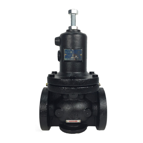
GD-200 Series
Model GD-200、200C、200H
Pressure Reducing Valve
This symbol indicates a potentially hazardous situation
that, if not avoided, could result in death or serious injury.
This symbol indicates a hazardous situation that, if not
avoided, may result in minor or moderate injury.
Contents
-----
■EPDT-09b■
Advertisement
Table of Contents

Related Manuals for Yoshitake GD-200 Series


Summary of Contents for Yoshitake GD-200 Series
-
Page 1: Table Of Contents
GD-200 Series Model GD-200、200C、200H Pressure Reducing Valve Please read this bulletin thoroughly before using the pressure reducing valve, so that you may do so correctly and safely. Please carefully store this bulletin in a handy place. ―――――― The following safety symbols are used in this manual. ――――― This symbol indicates a potentially hazardous situation Warning that, if not avoided, could result in death or serious injury. ... -
Page 2: 1.Features
GD-200 Series pressure reducing valves are widely used for construction equipment, air conditioning, plant equipment, industrial plant facilities and other application. This product can provide stable outlet pressure and big capacity. 1.Features 1) As pressure balanced structure is introduced, outlet pressure can be kept at a constant level without influence of inlet pressure. 2) Valve seat is made of stainless steel to ensure superior preventing abrasion and durability. 3) Rubber disc is used at the valve body to effectively eliminate leaks. 4) Maintenance is easy. 2.Specifications & Performance 2.1 Specifications Table 1 Model GD-200 GD-200C GD-200H Application(Fluid) water、air、oil (kerosene、heavy oil A・B) Nominal Size 15A〜150A Inlet Pressure(MPa) 1.0 or less 2.0 or less 15A〜50A : 15A〜80A : (A)0.05〜0.25 (B)0.26〜0.7 (C)0.5〜1.0 Reduced (A)0.05〜0.25 (B)0.26〜0.7 65A、80A : Pressure(MPa) ... -
Page 3: 2.2 Flow Rate Characteristics Chart
Caution Please collate with attached nameplate and specification of ordered model. ※Please consult factory in case they do not match each other. 2.2 Flow Rate Characteristics Chart Shut-off press. rise Flow rate Fig.1 Flow Rate Characteristics Chart ※Off-set Table 2 Nominal size Spring division Off-set (A)、(B) Setting range 0.05〜0.7MPa Within 0.05MPa 15A〜50A (C) Setting range 0.5〜1.0MPa Within 0.11MPa (A)、(B) Setting range 0.05〜0.7MPa Within 0.05MPa 65A、80A (C) Setting range 0.5〜0.9MPa Within 0.11MPa (A)、(B) Setting range 0.05〜0.5MPa Within 0.05MPa 100A (C) Setting range 0.5〜0.75MPa Within 0.11MPa (A) Setting range 0.05〜0.25MPa Within 0.05MPa 125A〜150A (B) Setting range 0.26〜0.5MPa ... -
Page 4: 3.Dimensions & Weight
3.Dimension & Weight Table 3 No. Parts Name 1 Body ... -
Page 5: 4.Operation
4.Operation If the adjusting screw⑬ is turned right, the diaphragm⑨ will be depressed with a adjusting spring ⑫ and valve disc ④ connected with spindle⑤ will open. The fluid which flowed in from the inlet side carries out the action which pushes up diaphragm⑨ through a sensing pipe at the same time it flows into a outlet side through the valve disc④ upper part. Load to diaphragm⑨ balances with load of adjusting spring⑫, and it adjust the opening of main valve to regulate the reducing pressure. ... -
Page 6: 5.Nominal Size Selection Method
5.Nominal Size Selection Method 5.1 Nominal Size Selection Chart < For Water > Nominal Size (A) ΔP:Differential Press. (MPa) Fig.6 Example of Selection When the inlet pressure (P ) is 0.5 MPa , the reduced pressure (P ) is 0.3 MPa and the flow rate is 7m /h, for instance , the size of the pressure reducing valve is selected as follows. Find the intersection point(A) of the differential pressure of 0.2 MPa with the flow rate of 7 m /h, the point(A) is between line of size 25A and 32A. Choose larger size 32A for application. ■EPDT-096b■ ... - Page 7 < For Air > Fig.7 Example of Selection When the inlet pressure (P ) is 0.5 MPa, the reduced pressure (P ) is 0.3 MPa and the flow rate is 800Nm /h, for instance, the size of the pressure reducing valve is selected as follows. Find the intersection point (A) of the inlet pressure (P ) 0.5 MPa and reduced pressure (P ) 0.3 MPa and go straight down from the point (A) to find the intersection (B) crossing the flow rate line. The point (B) is between line of 32A and 40A,and choose larger size 40A for application. ■EPDT-096b■ ...
-
Page 8: 5.2 Selection Formula For Nominal Size
5.2 Selection Formula for Nominal Size ・Cv value Table 5 Nominal Size 15A 20A 25A 100A 125A 150A Cv value 2.5 4 5 8 12 16 28 36 68 75 ・Cv Value Calculation Formula < For Gas > > ≤ In case of In case of ... -
Page 9: 6. Installation
6. Installation 6.1 Example of Piping ●For Water Fig.9 ●For Air Fig.10 ■EPDT-096b■... - Page 10 6.2 Precautions before operation Caution (1) Since it is weight thing, this product should use lifting equipment etc., and please support a product certainly and install it in piping. ※There is a possibility that it may be injured, by fall of product. (2) Do not disassemble the valve unreasonably. ※ Disassembling the valve at your discretion may affect the original performance. (3) Remove foreign matter and scales from the lines before connecting the valve. ※Failure to do so may prevent the valve from functioning correctly. (4) Install a strainer at the valve inlet side. ※Failure to do so may hamper correct pressure control, which affects the original performance. ※By sunshine or atmosphere temperature rise, the fluid in piping carries out volume expansion, failure of the valve and the external leak of fluid occur, and there is danger of circumference contamination. (5) Install a safety valve at the valve outlet sides for alarms. ※Failure to do so prevents problem identification, resulting in equipment ...
-
Page 11: 7. Operating Procedure
(14) If the large valve is used for gas, install a reducer to prevent excessive flow speed. ( The flow speed made in pipings is appropriate, if it is 15m/s or less.) (15) Above the center of the pipe line, be sure to reserve enough space larger than H (Fig.3). Please see the following table. Table 7 (mm) Nominal Size 15A 20A 80A 100A 125A 150A 500 500 800 1000 1200 1400 Fig.11 7. Operating Procedure 7.1 Precautions for pressure reducing valve operation Warning Do not touch the valve directly with bare hands. ※Doing so may result in burns. Caution (1) Close the stop valves before and after the pressure reducing valve, and remove all foreign matter and scales via the by-pass line before operation. ... -
Page 12: 7.2 Adjustment Procedure
7.2 Adjustment Procedure Caution (1) Follow the steps below, and slowly turn the adjusting screw to set pressure. Incorrect adjustment may cause hunting, water hammer, etc., resulting in damage to the valve and other equipment. (1) Close the stop valves at both sides of the pressure reducing valve, and thoroughly purge the system through the by-pass line, with the by-pass valve opening adjusted so that the safety relief valve is not activated. When completed, be sure to close the by-pass valve. (2) Slowly open the inlet stop valve, then open the outlet stop valve slightly, allowing a trickle to be discharged. (3) Loosen the lock nut⑭, and slowly turn the adjusting screw⑬ (clockwise to increase, counterclockwise to reduce) while observing the pressure gauge on the outlet side. (4) Slowly open the outlet stop valve to its full-open position. (5) After the adjustment, tighten the lock nut⑭. (6) In case of secondary pressure for size 65A to 150A is unstable because of an air obstruction or etc., adjust opening of needle valve at detecting pipe. Adjusting screw⑬ Reduced pressure goes down. Lock nut⑭ Reduced pressure goes up. Fig.12 -11- ■EPDT-096b■ ... -
Page 13: 8. Maintenance Procedure 8.1 Troubleshooting
8. Maintenance Procedure 8.1 Troubleshooting Problem Causes Solutions Pressure does not 1. Incorrect pressure is being 1. Correct the pressure being used. rise to desired used. (Refer to the “Specifications”.) level. 2. The conductor pipe⑮ is clogged 2. Disassemble and clean the conductor with foreign matter. pipe. 3. Nominal size is too small for 3. Replace with the correct nominal these specifications. sized item. 4. Incorrect adjustment. 4. Re-adjust according to the adjustment procedure. (Refer to the “Adjustment Procedure”.) 5. Strainer is clogged. 5. Disassemble and clean. ... -
Page 14: 8.2 Precautions During Disassembly And Inspection
8.2 Precautions during disassembly and inspection Warning Completely discharge internal pressure from the valves, lines, and equipment, and cool the valve down to a level where you can touch it with bare hands before disassembly and inspection. ※Failure to do so may result in injury or burns due to residual pressure or spillage around the valve. Caution ( 1 ) Perform periodical inspection to maintain product functions and performance. ※ General users shall request countermeasures to installers or maintenance companies. (2) The pressure reducing valve shall be disassembled and inspected by qualified persons. (3) Rubber parts and components shown below are consumables. Note that the life expectancy depends on the conditions under which they are used. Table 8 Serviceable life Parts name/number ... -
Page 15: 8.4 Precautions During Disassembly
Nominal Size 15A〜50A To remove the retainer guide⑧ easily, install the spring plate⑪ and U nut ⑱ to spindle⑤ again and pull the spring plate⑪.(Fig.4) U nut⑱ Spindle⑤ Spring plate⑪ Fig.13 Nominal Size 65A〜100A To remove the retainer guide⑧ easily, screw the retainer guide clamping bolt ⑯ to retainer guide⑧ and pull it.(Fig.5) Retainer guide clamping bolt⑯ Retainer guide⑧ Fig.14 8.4 Precautions during disassembly (1) Make sure that the diaphragm⑨, the valve seat③, and the valve④ have no scratches. (2) Apply the silicon grease to the O-Ring⑦ after confirm whether there are any flaw on the O-Ring⑦. (3) Install the spring chamber② after the confirm whether the border of diaphragm ⑨ is fitted with the groove of body①. ( 4... -
Page 16: 8.5 Exploded Drawing
8.5 Exploded drawing ・Parts with the ※ are consumable. Please contact us for purchase of these consumable parts. -15- ■EPDT-096b■ ... - Page 17 Fire, flood, earthquake, thunder and other natural disasters. Consumable parts such as O-ring, gasket, diaphragm and etc. Yoshitake is not liable for any damage or loss caused by malfunction or defect of the product. INTERNATIONAL DEPT. 7-3, Futanocho, Mizuho, Nagoya, Aichi, 467-0861, Japan...
Need help?
Do you have a question about the GD-200 Series and is the answer not in the manual?
Questions and answers