Table of Contents
Advertisement
Quick Links
Pressure Reducing Valve
Installation & Operation Manual
Please read this manual thoroughly before using the pressure reducing valve, so that
you may do so correctly and safely.
Please carefully store this manual in a handy place.
- --- -The following safety symbols are used in this manual. -- -- -
This symbol indicates a potentially hazardous situation that, if not avoided,
Warning
could result in death or serious injury.
This symbol indicates a hazardous situation that, if not avoided, may result
Caution
in minor or moderate injury. ("Caution" may also be used to indicate other
unsafe practices or risks of property damage.)
1. Features ············································································· 1
2. Specifications ································································ 1
3. Dimensions and Construction
3.1 Dimensions and Weight ···················································· 2
3.2 Construction ·································································· 3
4. Operation ··········································································· 3
5.1 Nominal Size Selection Chart ············································ 4
5.2 Flow Rate Characteristics Chart ········································ 5
5.3 Pressure Characteristics Chart ·········································· 5
6.1 Piping Example ······························································ 6
6.2 Warning and precaution on installation ··························· 6
7.1 Warning and precaution on operation ································· 7
7.2 Adjustment Procedure ···················································· 7
8. Maintenance Procedure ························································· 7
8.2 Troubleshooting ····························································· 8
9. Exploded Drawing ······························································· 9
After Sales Service
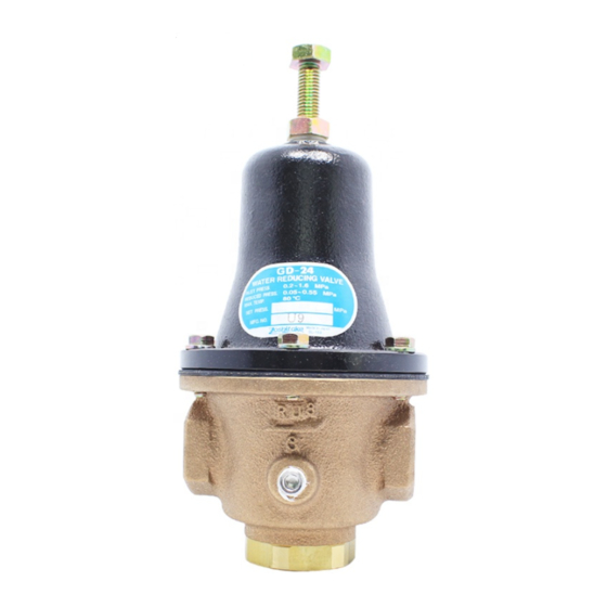
Model GD-24/24B
Contents
■EPDT-209■
Advertisement
Table of Contents

Related Manuals for Yoshitake GD-24


Summary of Contents for Yoshitake GD-24
-
Page 1: Table Of Contents
Model GD-24/24B Pressure Reducing Valve Installation & Operation Manual Please read this manual thoroughly before using the pressure reducing valve, so that you may do so correctly and safely. Please carefully store this manual in a handy place. - --- -The following safety symbols are used in this manual. -- -- -... -
Page 2: Features
GD-24/24B water pressure reducing valve can be used as a pressure control unit in water supply systems of general residential housing, high-rise buildings, industrial plant, and factory equipment. It can also be used to provide stable water pressure in high-rise apartment units, and for hilly districts where each house requires an individual water supply system. -
Page 3: Dimensions And Weight
3. Dimensions & Construction 3.1 Dimensions & Weight 【GD-24/24B】 (mm) Nominal Weight size (kg) Rc 1/2 41.5 Rc 3/4 Rc 1 Rc 1 1/4 Rc 1 1/2 Rc 2 14.3 【Pressure gauge】 ■EPDT-209■... -
Page 4: Construction
3.2 Construction Name of parts Body Spring Chamber Valve Valve Seat Disc Suspension Metal Diaphragm Shell Diaphragm Spring Plate Adjusting Screw Lock Nut Washer Set Screw Spring Lock Washer Adjusting Spring O-ring Bolt Sealed Nut Spring Plug Label Spring Washer 4. -
Page 5: Nominal Size Selection
5. Nominal Size Selection 5.1 Nominal Size Selection Chart (For Water) Nominal size ΔP: Inlet/reduced pressure differential (MPa) Note: *Considering such factors as noise and durability, a 2 m/s flow velocity within the pipe is ideal. ●Cv Value Nominal size Cv value ●Calculation formula for Cv value Δ... -
Page 6: Flow Rate Characteristics Chart
5.2 Flow Rate Characteristics Chart 5.3 Pressure Characteristics Chart ■EPDT-209■... -
Page 7: Installation
6. Installation 6.1 Piping Example 6.2 Warning and precaution on installation Warning In case installing safety relief valve as safety device at outlet side, joint relief pipe at outlet of safety relief valve and guide it to safety place where steam can relief out. Caution ( 1 ) Do not disassemble the valve unreasonably. -
Page 8: Operating Procedure
*Water scales developed in the piping may cause erratic operation of pressure reducing valve. 7.2 Adjustment Procedure GD-24/24B pressure reducing valve is set at 0.1MPa at the factory. Change the set pressure as appropriate. Wrong or poor adjustment may cause hunting, scale buildup or water hammer, or severely damage relevant parts. -
Page 9: Warning And Precaution On Maintenance And Inspection
8.1 Warning and precaution on maintenance and inspection Warning The pressure reducing valve shall be disassembled and inspected by qualified persons. ( 1 ) Completely discharge internal pressure from the valves, lines, and equipment, and cool the valve down to a level where you can touch it with bare hands before disassembly and inspection. -
Page 10: Exploded Drawing
9. Exploded Drawing Adjusting Screw Spring Lock Washer Diaphragm Shell Lock Nut Diaphragm Sealed Nut Bolt Suspension Metal Spring Washer Pressure Gauge Spring Chamber Spring Plate Body Adjusting Spring Valve Seat Set Screw Washer Disc Valve Spring O-ring *15/20A no Washer. ・Part names shown in boxes are consumable parts.
Need help?
Do you have a question about the GD-24 and is the answer not in the manual?
Questions and answers