Table of Contents
Advertisement
Quick Links
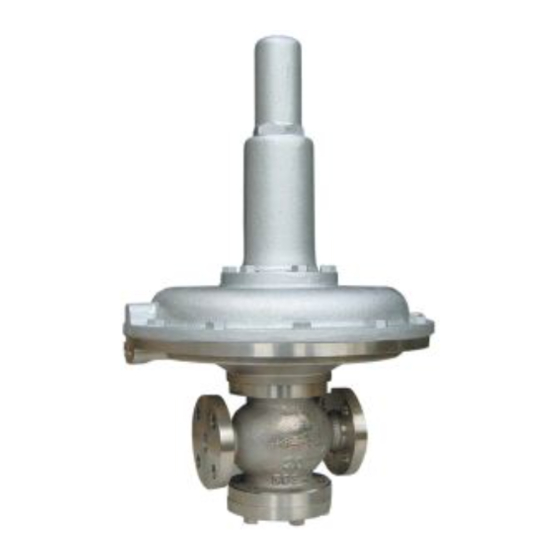
PRESSURE REDUCING VALVE
Handling Precautions and Limitation of Warranty
Thank you for purchasing the Yoshitake pressure reducing valve. It is important that you carefully
read through this manual before using it for your proper and safety use.
Keep this manual in convenient place so you can refer to it as you need.
If the product becomes failure or defective because it has been mishandled or improperly operated,
the user shall agree to pay charges for repair or replacement.
----Please note the following caution icons and conventions used in this manual.----
Warning
Caution
1.
2.
3.
4.
Nominal size selection
5.
5.2
5.3
5.4
6.
6.1
6.2
6.3
7.
7.1
7.2
7.3
8.
8.1
8.2
8.3
8.4
After Sale Service
Model GD-400・ ・ ・ ・ 400SS
Product Manual
Failure to comply with a warning message could result in severe
personal injury or death.
Failure to heed a caution message could result in personal injury or
damage to the equipment or facilities.
----------------------------------------------------------- 1
-------------------------------------------------------------------- 1
-------------------------------------------------------- 2
----------------------------------------------------------- 3
Nominal size selection
5.4.1
5.4.2
7.2.1
Pressure setting is preset
7.2.2
---------------------------------------------------------- 13
-------------------------------------------------------- 14
Contents
---------------------------------------------- 4
---------------------------------------- 4
------------------------------------- 5
---------------------------------------- 6
--------------------------------------------- 7
------------------------ 7 ~ 8
----------------------------------------- 9
------------------------------- 9
---------------------------------- 10
--------------------------------------- 10
------------------------------------------- 11
------------------------------------- 15 ~ 2 4
-------- 4
--- 12
■ E P D T - 1 7 9 c ■
Advertisement
Table of Contents

Related Manuals for Yoshitake GD-400


Summary of Contents for Yoshitake GD-400
-
Page 1: Table Of Contents
Product Manual Handling Precautions and Limitation of Warranty Thank you for purchasing the Yoshitake pressure reducing valve. It is important that you carefully read through this manual before using it for your proper and safety use. Keep this manual in convenient place so you can refer to it as you need. -
Page 2: Product Application
1. Product application The GD-400/400SS pressure reducing valve is developed primarily for extremely low pressure control of air or nitrogen gas in a chemical, food or petrochemical plant. 2. Specification CAUTION Check the data on the nameplate of the delivered product against the specifications of your order sheet. -
Page 3: Dimensions And Parts
3. Dimensions and parts External sensing port GD-400,400SS Dimensions ( m m ) Nominal Weight size (kg) 29.0 ( 32.0 ) 29.0 ( 32.0 ) 30.0 ( 33.0 ) ( ) : G D-400SS Parts Parts Parts № № 1 Body... -
Page 4: Theory Of Operation
4 . 4 . 4 . 4 . T h e o r y o f o p e r a t i o n T h e o r y o f o p e r a t i o n T h e o r y o f o p e r a t i o n T h e o r y o f o p e r a t i o n The adjusting screw... -
Page 5: Pressure R Educing Valve Specifications Selection Chart
5. Nominal size selection 5.1 Pressure reducing valve specification selection chart 5.2 Flow characteristics chart 5.3 Pressure characteristics chart ) 1 0 . 0 ( k 9 . 5 9 . 0 8 . 5 8 . 0 7 . 5 7 . -
Page 6: Nominal Size Selection Chart
5.4 Nominal size selection 5.4.1 Nominal size selection chart Determination of nominal size when the inlet pressure is in a range 2.5 kPa to 200 kPa (fluid: air, at 20 ℃ ) E xample 《 》 Select the nominal size of a pressure reducing valve to be operated with the inlet pressure 10 kPa and reduced pressure 3 kPa at a flow rate 15 m /h (normal condition): First locate the point (A) on the chart where the inlet pressure 10 kPa line and reduced pressure 3 kPa line... -
Page 7: Calculating A Nominal Size
5.4.2 Calculating a nominal size Determine the required Cv value by using the formula shown below and then the corresponding nominal size based on the Cv value. To calculate a Cv value (for selecting nominal size when valve-inlet pressure is 2.5 kPa up to 200 kPa): If P >P... -
Page 8: Installation Guideline
6. Installation guideline 6.1 Diagram of piping example F i g . 1 6.2 Warning and precaution on installation WARNING (1) The pressure reducing valve is heavy: check its weight by referring to the "3. Dimensions and parts". Securely holding the valve with a lifting gear, attach and connect it to the piping. - Page 9 (4) Connect a primary pressure regulating valve or safety valve to the outlet side of the pressure reducing valve to protect it and outlet side equipment. B e sure to provide the protective valve to avoid system damage. (If the outlet pressure ※...
- Page 10 6.3 How to connect External sensing port Connect the sensing pipe( 8 -2m)and joints( 8 -R3/8)as shown in Fig.3 below. φ φ Joint ( φ 8 -R3/8) Put a sealing tape around the thread of the joint and screw it into the connection to the pressure gauge.
-
Page 11: Adjustment
7.2 Adjustment Read again 6.1 Diagram of piping example and 7.1 Warning and precaution on operation. 7.2.1 Pressure setting is not preset (the user does not require pressure presetting) (1) Verify that stop valves V and V are closed. (2) Adjust the stop valve V on the bypass pipe to an opening so that the primary pressure regulating valve (or safety valve) will not be activated. -
Page 12: Adjustment Of Needle Valve
7.3 Adjustment of needle valve WARNING Do not adjust the needle valve without understanding its purpose and function. N ever attempt to excessively open (turn CCW) the needle valve. Fluid will blow out. If ※ the fluid is hot, you may suffer burns. CAUTION Never completely close the needle valve. -
Page 13: Maintenance Guideline
Life expectancy of consumable parts depends on frequency and condition of use. Rough standard of life estimation is given below. (Part number shown in the table below refers to the number in Section 8.3, Fig.4 GD-400 exploded drawing.) Parts Part number... -
Page 14: Troubleshooting
8.2 Troubleshooting (see 8.3 Exploded draiwing, Fig.4; 8.4 Troubleshooting procedure) Problem Presumable cause Corrective action 1. Leakage from the stop valve on bypass 1. Close the stop valve. If leakage continues, pipe. replace the stop valve. 2. External sensing pipe tube is not 2. -
Page 15: Exploded Drawing
8.3 Exploded view ※ A vailable as consumable part Fig. 4 Exploded drawing ■ E P D T - 1 7 9 c ■... -
Page 16: Troubleshooting Procedure
8.4 Troubleshooting procedure Disassembling warning WARNING Before beginning disassembling or inspection, completely release all pressure from the pressure reducing valve, piping and equipment. If the fluid used is hot, wait until the valve cools down. Never touch valve with bare hands while they are still warm. ※... - Page 17 Action (5) : Clean the needle valve and hole of lower diaphragm casing. Action (6) : Turn the needle valve to full close and then open by turning one turn in reverse direction with a flat head screwdriver. Presumable cause I.4: Foreign object is pinched between valve disc and valve seat; or these parts are damaged.
- Page 18 Action (11) : While securely holding top diaphragm plate with hand, unscrew 3 hexagon socket head ○ cap bolts ○ (Hexagon socket head cap bolt and locknut will be checked for looseness in 2 6 2 6 2 6 2 6 2 5 2 5 2 5 2 5 ○...
- Page 19 Action (13) : Remove 6 hexagon head bolts from the lower cover. Remove spring , spindle ○ ○ ○ disc , valve , spring washer , and hexagonal nuts ○ ○ ○ ○ (Presumable cause I.8: Foreign object is pinched between spindle and slide of 1 2 1 2 1 2 1 2 ○...
- Page 20 Action (16) : Place a new disc ⑩ in recess on the valve ⑪ . Action (17) : Attach disc ⑩ , valve ⑪ , spring washer ⑬ into spindle ⑫ and secure with hexagon nut ⑭ . (Tightening torque:16 N•m) Action (18) : Attach spindle ⑫...
- Page 21 Action (20) : While securely holding top diaphragm plate with hand, tighten 3 hexagon socket head ○ cap bolts . (Tightening torque: 4 N·m) ○ Note: Do not attempt to twist top diaphragm plate any further. This may damage 2 3 2 3 2 3 2 3 ○...
- Page 22 Presumable cause I.8: Foreign object is pinched between spindle ⑫ ⑫ ⑫ ⑫ and slide of bottom guide ⑯ ⑯ ⑯ ⑯ . Action (27) : Follow steps in Actions (7) to (13). After removing the object, go to Actions (18) to (23) . Presumable cause I.9: Hexagon nut ⑭...
- Page 23 Problem II: Reduced pressure does not reach the prescribed value. Or, fluid fails to flow. Presumable cause II.12: The strainer at the inlet is clogged. Action (33) : Clean the strainer screen. Presumable cause II.13: Needle valve is clogged by foreign materials. 3 7 3 7 3 7 3 7 ○...
- Page 24 Presumable cause III.18: Hexagon head bolt on top diaphragm case becomes loose. 2 8 2 8 2 8 2 8 ○ ○ ○ ○ Action (41) : Retighten hexagon head bolt of top diaphragm case. ○ Presumable cause III.19: Hexagon socket head cap bolt and locknut 2 6 2 6 2 6 2 6 2 5 2 5 2 5 2 5...
- Page 25 Action (46): Place the bottom diaphragm case and secure it with hexagon socket head cap bolt ⑥ . (Tightening torque: 12N·m) → → → → Action (47): Follow steps described in Actions (19) to (23). ■ E P D T - 1 7 9 c ■...
Need help?
Do you have a question about the GD-400 and is the answer not in the manual?
Questions and answers