Table of Contents
Advertisement
Quick Links
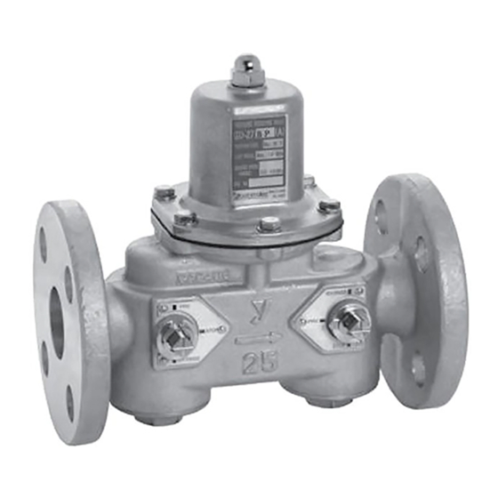
Pressure Reducing Valve
Thank you very much for choosing the Yoshitake's product. To ensure the correct and safe use of the product,
please read this manual before use. This manual shall be kept with care for future reference.
The symbols used in this manual have the following meanings.
Warning
Caution
1. Usage of the Product ·················································· 1
3. Dimensions and weights ·············································· 5
4. Structure ·································································· 6
5. Operation ································································· 8
9. Exploded view ························································· 16
MODEL GD-27BP
with By-pass
PRODUCT MANUAL
This symbol indicates a potentially hazardous situation that, if not avoided, could
result in death or serious injury.
This symbol indicates a hazardous situation that, if not avoided, may result in
minor or moderate injury or may result in only property damage.
Table of Contents
2.1 Specifications ······················································ 1
2.2 Nominal size selection ······································ 2 - 3
2.3 Flow rate characteristics chart ································· 3
2.4 Pressure characteristics chart ································· 4
2.5 Noise characteristics chart ····································· 4
6.1 Piping example ···················································· 8
6.2 Precaution for installation ······································· 8
7.1 Precaution for operation ······································· 10
7.2 Adjusting procedure ············································ 10
8.1 Troubleshooting ················································· 10
8.2 Precaution for maintenance and inspection ·············· 11
8.3 Disassembly ····················································· 12
8.4 Precaution for reassembly ···································· 14
8.5 Tool for regulation and maintenance ······················· 15
0
EPDT-278
Advertisement
Table of Contents

Related Manuals for Yoshitake GD-27BP


Summary of Contents for Yoshitake GD-27BP
-
Page 1: Table Of Contents
By-pass PRODUCT MANUAL Thank you very much for choosing the Yoshitake’s product. To ensure the correct and safe use of the product, please read this manual before use. This manual shall be kept with care for future reference. The symbols used in this manual have the following meanings. -
Page 2: Usage Of The Product
2. Specifications 2.1 Specifications Model GD-27BP Nominal size 20-100A Application Cold and hot water Inlet pressure 1.0 MPa or less... -
Page 3: Nominal Size Selection
2.2 Nominal size selection Rated flow table (The pressure difference before and after the product is 0.15 MPa or more) Nominal size 100A Rated flow (L/min) Nominal size selection chart Nominal size 20A - 50A EPDT-278... -
Page 4: Flow Rate Characteristics Chart
Nominal size selection chart Nominal size 65A -100A 2.3 Flow rate characteristics chart Offset Reduced pressure Offset range 0.10MPa or 0.05 - 0.35MPa below 0.15MPa or 0.30 - 0.70MPa below EPDT-278... -
Page 5: Pressure Characteristics Chart
2.4 Pressure characteristics chart This chart shows variation in the reduced pressure when the inlet pressure of 0.6 MPa is changed between 0.15 MPa and 1.0 MPa after the reduced pressure is set at 0.1 MPa. 2.5 Noise characteristics chart (Fluid: Water) EPDT-278... -
Page 6: Dimensions And Weights
3. Dimensions and Weights (mm) Weight Size (kg) 100A EPDT-278... -
Page 7: Structure
4. Structure Switching of three functions (pressure reducing function, by-pass function and stop function) is conducted by operating stems at inlet side and outlet side and pointing the arrow at a certain point of the plate. See the next page for the arrow position and fluid flow in each function. Caution 1. - Page 8 ■Pressure reducing function ■By-pass function ■Stop function EPDT-278...
-
Page 9: Operation
5. Operation Spring [35] is compressed by adjusting screw [32] and make diaphragm [16] pushed down, and thereby open disc [12] directly connected to it. Fluid coming in from the inlet side flows out from the upper part of disc [12] to the outlet side, and passes through reduced pressure... - Page 10 4. Install a safety relief valve at the outlet side of the product for protection of equipment at outlet side. * Failure to follow this notice may result in damage of the equipment. 5. Be sure to install pressure gauges at the inlet and outlet sides of the product. * Failure to follow this notice hampers correct pressure adjustment.
-
Page 11: Operation Procedure
7. Operation procedure 7.1 Precaution for operation When the product is used for hot fluid, do not touch the product with bare hands. Warning * The product having hot fluid may scald your skin. Caution 1. Before leading fluid into the product, switch the product function to by-pass function and remove foreign substances and scale from the piping completely. -
Page 12: Maintenance
8. Maintenance 8.1 Troubleshooting (See “4. Structure” on Page 6 and “9. Exploded view” on Page 16.) Trouble Cause Remedy 1. There are foreign substances stuck 1. Disassemble the product and remove between disc [12] and valve seat the foreign substances. If scratch is [3], or scratches on them. -
Page 13: Precaution For Maintenance And Inspection
8.2 Precaution for maintenance and inspection (See “4. Structure” on Page 6 and “9. Exploded view” on Page 16.) Warning 1. Completely discharge the pressure inside of the product, piping and equipment before disassembly and inspection. Disassembly and inspection must be done by experienced professional or valve manufacturer. - Page 14 Nominal size 65A to 100A: Screw bolt [15] into valve seat [3], and pull them up together. Secure the part A of the spindle [6] (two faces), loosen the U-nut [14] with a tool, and remove disc [12], and O-ring [11]. EPDT-278...
-
Page 15: Precaution For Reassembly
8.4 Precaution for reassembly (See “9. Exploded view” on Page 16) Caution 1. Check to see that there is no foreign substances inside the body and on each part. *Foreign substances prevent the product from functioning properly. To avoid the problem, remove foreign substances. -
Page 16: Tool For Regulation And Maintenance
8.5 Tool for regulation and maintenance Part No. Parts Size of tool Tool name 20-25A:3 mm 32-50A:4 mm Spindle 65-80A:6 mm 100A: 7 mm 20-25A:10 mm 32-40A:13 mm U-nut 50-80A: 17 mm 100A: 19 mm 20-25A: 9 mm 32-40A: 12 mm Stem 50A: 14 mm... -
Page 17: Exploded View
9. Exploded view Note) Parts shown in the rectangle boxes are available as consumable supply and parts kit Parts included are below. Parts kit name Parts included Diaphragm Diaphragm [16] Disc Disc [12] O-ring set O-ring([4],[5],[8],[9],[11] and [34]) Ball valve part cannot be disassembled. EPDT-278...
Need help?
Do you have a question about the GD-27BP and is the answer not in the manual?
Questions and answers