Table of Contents
Advertisement
Quick Links
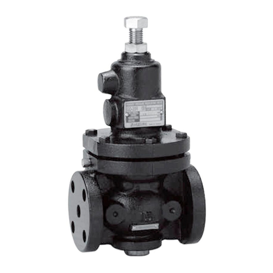
Primary Pressure Regulating Valve
Please read this bulletin thoroughly before using the pressure reducing valve, so that you
may do so correctly and safely. Please carefully store this bulletin in a handy place.
------The following safety symbols are used in this manual. -----
This symbol indicates a potentially hazardous situation that, if not
Warning
avoided, could result in death or serious injury.
This symbol indicates a hazardous situation that, if not avoided, may
Caution
result in minor or moderate injury.
1.1 Specifications ··········································································· 1
1.2 Flow Rate Characteristics Chart ····················································· 2
2. Dimensions & Weight ····································································· 2
3. Operation ····················································································· 4
4.1 Nominal Size Selection Chart ························································· 5
4.2 Selection Formula for Nominal Size ················································· 7
4.3 Pressure Sustaining Valve Selection ················································ 8
5.1 Example of Piping ······································································· 9
5.2 Precautions before Operation ························································ 11
6.1 Precautions for Operation ··························································· 12
6.2 Adjustment Procedure ································································ 13
7.1 Troubleshooting ········································································ 14
7.2 Precautions for Maintenance ························································ 15
7.3 Periodic Inspection ···································································· 15
7.4 Disassembly ············································································· 15
7.5 Assembly ·················································································· 16
8 Exploded Drawing ··········································································· 17
After Sales Service
Model GD-20R
Pressure Sustaining Valve
Contents
■EPDT-023c■
Advertisement
Table of Contents

Related Manuals for Yoshitake GD-20R


Summary of Contents for Yoshitake GD-20R
-
Page 1: Table Of Contents
Model GD-20R Primary Pressure Regulating Valve Pressure Sustaining Valve Please read this bulletin thoroughly before using the pressure reducing valve, so that you may do so correctly and safely. Please carefully store this bulletin in a handy place. ――――――The following safety symbols are used in this manual. ―――――... -
Page 2: Specifications & Performance
1. Specifications & Performance 1.1 Specifications Table 1 GD-20R Model Hot and cold water, Air, Oil (+) (kerosene、heavy oil A・B) Application (Fluid) and Other non-dangerous fluids 15~80A 100~150A Nominal size (A) 0.05~0.25MPa (A)0.05~0.25MPa Inlet pressure (MPa) (B) 0.26~0.7MPa (B)0.26~0.5MPa Installation posture... -
Page 3: Dimensions & Weight
2. Dimension & Weight < 15 - 50A > Name plate Fig. 2 *The parts shape differs according to the nominal size. Table 4 Dimension & Weight Table 3 Weight Parts Name Parts Name Size (kg) Body U Nut Spring chamber U Nut Lower cap O ring... - Page 4 < 65 - 150A > 銘板 Fig. 3 *The parts shape differs according to the nominal size. Table 6 Dimension & Weight Table 5 Weight Parts Name Parts Name Size (kg) Body O ring 40.0 Spring chamber O ring 43.7 Lower cap O ring 100A...
-
Page 5: Operation
3. Operation Sensing chamber Detail view Fig. 4 *The parts shape differs according to the nominal size. If the adjusting screw [15] is turned right, the diaphragm [11] will be depressed with the adjusting spring [14] and valve disc [9] connected with spindle [6] will close. (a) Fluid passes along a conductor pipe [15] and the sensing chamber under the diaphragm [11]. -
Page 6: Nominal Size Selection Method
4. Nominal Size Selection Method When selecting pipe size, please take piping condition and application into consideration and secure a safety rate of 20% or more for the performance value. 4.1 Nominal Size Selection Chart <For Liquid> ΔP : Differential press. (MPa) ・... - Page 7 <For Air> :Inlet Press.(MPa) ・ Nominal Size ・ 図 6 呼び径選定図(気体用) Fig. 6 Example of Selection When the inlet pressure (P1) is 0.5 MPa, the outlet pressure (P2) is 0.3 MPa and the flow rate is 400Nm3/h, for instance, the size of the pressure regulating valve is selected as follows. Find the intersection point (A) of the inlet pressure (P1) 0.5 MPa and outlet pressure (P2) 0.3 MPa and go straight down from the point (A) to find the intersection (B) crossing the flow rate line.
-
Page 8: Selection Formula For Nominal Size
4.2 Selection Formula for Nominal Size When selecting the nominal diameter by calculation, use the formula to find the required Cv value based on the usage conditions, and then select the nominal diameter with a Cv value that satisfies that value (see Table 7). Table 7 Nominal Size 20A 25A... -
Page 9: Pressure Sustaining Valve Selection
4.3 Pressure Sustaining Valve Selection For selection of Pressure sustaining valve, follow the directions listed below. Conditioner Two way valve Model TA-2,3 Air Vent Model GD-20R Model TA-2,3 Air Vent Primary Pressure Air Vent Regulating Valve Model SU-20 Strainer Refrigerator... -
Page 10: Installation
〇Primary Pressure Regulating Valve Stop valve Stop valve Model PG-2 Model PG-2 Model SU-20 Press. gauge Press. gauge Strainer Model GD-20R Stop valve Stop valve Primary Pressure for drainage for drainage Regulating Valve By-pass stop valve Fig. 9 〇 Pressure Sustaining Valve... - Page 11 By-pass Model TA-2,3 stop valve Air Vent Stop valve *About 1m Model SY-40 Strainer Press. gauge Stop valve Model GD-20R Pressure Sustaining Valve (15-80A) Compound press. gauge Globe valve Stop valve for drainage Extend the piping as deep *Depending on the piping size, it may exceed 1m, into the water as possible.
-
Page 12: Precautions Before Operation
Precautions before Operation Caution Depending on the water quality, brass parts may corrode or be promoted, causing product malfunction. In an environment where corrosion may occur, select a product made of a compatible material such as stainless steel. If components having negative influence on internal parts are included in fluid or surroundings, deterioration of rubber parts is accelerated and then outside leakage or functional disorder is caused. -
Page 13: Operating Procedure
≪ Inspection space≫ Table 10 (mm) Size 100A 125A 150A 1000 1200 1400 Fig. 12 6. Operating Procedure 6.1 Precautions for Operation Warning (1) When the product is used for hot fluid, do not touch the product with bare hands. * The product having hot fluid may scald your skin. -
Page 14: Adjustment Procedure
Caution (1) Before leading fluid into the product, close the stop valves at the inlet and outlet of the product and remove foreign substances and scale from the piping completely by using a bypass line. * Failure to follow this notice may prevent the product from functioning properly due to the ingress of foreign substances and scale into the product. -
Page 15: Maintenance Procedure
7. Maintenance Procedure 7.1 Troubleshooting Problem Causes Solutions 1. Nominal size is too small for these 1. Replace with the correct nominal sized item. (Refer to the “4. Nominal Size Selection specifications. Method”.) 2. Incorrect adjustment. 2. Re-adjust according to the adjustment procedure. -
Page 16: Precautions For Maintenance
7.2 Precautions for Maintenance Warning (1) The valve shall be disassembled and inspected by qualified persons. (2) Completely discharge internal pressure from the valves, lines, and equipment, and cool the valve down to a level where you can touch it with bare hands before disassembly and inspection. -
Page 17: Assembly
[Nominal Size: 15A~50A] To remove the retainer guide [5] easily, install the spring plate [12] and U nut [17] to spindle [6] again and pull the spring plate [12]. (Fig. 14) Spindle ⑥ U nut ⑰ Spring plate⑫ Fig. 14 [Nominal Size: 65A~150A] To remove the retainer guide [5] easily, screw the bolt [28] to retainer guide [5] and pull it. -
Page 18: Exploded Drawing
8. 分解図 Fig. 16 Parts with in the ※ are consumable. Please contact us for purchase of these consumable parts. - 17 - ■EPDT-023c■... - Page 19 Fire, flood, earthquake, thunder and other natural disasters. Consumable parts such as O-ring, gasket, diaphragm and etc. Yoshitake is not liable for any damage or loss caused by malfunction or defect of the product. PDD-046f...
Need help?
Do you have a question about the GD-20R and is the answer not in the manual?
Questions and answers