Table of Contents
Advertisement
Quick Links
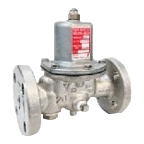
MODEL GD-28S-NE, GD-29S-NE
Pressure Reducing Valve
Thank you very much for choosing the Yoshitake's product. To ensure the correct and safe use of the product,
please read this manual before use. This manual shall be kept with care for future reference.
The symbols used in this manual have the following meanings.
Warning
Caution
2. Dimensions and weights ·········································· 5 - 6
3. Operation ································································· 7
7. Exploded view ··················································· 14 - 15
After Sales Service
PRODUCT MANUAL
This symbol indicates a potentially hazardous situation that, if not avoided, could
result in death or serious injury.
This symbol indicates a hazardous situation that, if not avoided, may result in
minor or moderate injury or may result in only property damage.
1.1 Specifications ······················································ 1
1.2 Nominal size selection ······································ 2 - 3
1.3 Flow rate characteristics chart ································ 3
1.4 Pressure characteristics chart ································· 4
1.5 Noise characteristics chart ····································· 4
4.1 Piping example ···················································· 7
4.2 Precaution for installation ··································· 8 - 9
5.1 Precaution for operation ········································ 9
5.2 Adjusting procedure ········································ 9 - 10
6.1 Troubleshooting ·················································· 10
6.2 Precaution for maintenance and inspection ·············· 11
6.3 Disassembly ················································ 11 - 12
6.4 Precaution for reassembly ···································· 12
6.5 Strainer cleaning procedure ·································· 13
Table of Contents
EPDT-351
Advertisement
Table of Contents

Related Manuals for Yoshitake GD-28S-NE


Summary of Contents for Yoshitake GD-28S-NE
-
Page 1: Table Of Contents
Pressure Reducing Valve PRODUCT MANUAL Thank you very much for choosing the Yoshitake’s product. To ensure the correct and safe use of the product, please read this manual before use. This manual shall be kept with care for future reference. -
Page 2: Specifications
1. Specifications 1.1 Specifications Model GD-28S-NE GD-29S-NE Nominal size 20A - 50A 20A - 100A Application Cold and hot water Inlet pressure 2.0 MPa or less 0.20 - 0.35 MPa Reduced pressure 0.30 - 0.70 MPa Min. differential pressure 0.05 MPa... -
Page 3: Nominal Size Selection
1.2 Nominal size selection Procedure of nominal size selection If the differential pressure before and after the valve is 0.15 MPa or more, select the nominal size from the rated flow table below. Rated flow table (The pressure difference before and after the product is 0.15 MPa or more) Nominal size 100A Rated flow (L/min) -
Page 4: Flow Rate Characteristics Chart
Nominal size 65A -100A Nominal size Flow rate L/min Inlet pressure Reduced pressure + 0.1 MPa Reduced pressure + 0.05 MPa 1.3 Flow rate characteristics chart Shut-off pressure rise (0.02 MPa) Set pressure Offset Flow rate Offset (Differential pressure after valve seat is 0.15MPa or more) Nominal size Pressure range Reduced pressure range... -
Page 5: Pressure Characteristics Chart
1.4 Pressure characteristics chart Inlet pressure MPa This chart shows variation in reduced pressure when the inlet pressure of 1.0 MPa is changed between 0.35 MPa and 2.0 MPa while the reduced pressure is set at 0.30 MPa. 1.5 Noise characteristics chart (Fluid: Water) Nominal size 20A –... -
Page 6: Dimensions And Weights
2. Dimensions and Weights Model GD-28S-NE (mm) Nominal Weight size (kg) Rc 3/4 Rc 1 Rc 1 1/4 Rc 1 1/2 Rc 2 239.5 EPDT-351... - Page 7 Model GD-29S-NE Nominal size 20A - 50A Nominal size 65A - 100A (mm) JIS 20KRF flanged Weight Nominal (kg) size n-φh 4-15 4-19 4-19 4-19 61 239.5 8-19 11.8 8-19 21.0 8-23 25.5 100A 8-23 40.5 EPDT-351...
-
Page 8: Operation
By-pass Pressure gauge Pressure gauge Safety relief valve Stop Stop GD-28S-NE Inlet side Outlet side valve valve Pressure reducing valve * Install a strainer on the inlet side of the pressure reducing valve of nominal size 65A to 100A. * Make sure that pipes 3m before and after the product, both the inlet side and outlet side, are of the same diameter. -
Page 9: Precaution For Installation
4.2 Precaution for installation Warning Please refer to “2. Dimensions and Weights.” for product weight. * Failure to follow this notice may cause a falling accident of the product, resulting in an injury. When installing a safety relief valve for equipment protection on the outlet side of the product, connect a blow-off pipe to the outlet side of the safety relief valve, and lead it to a place where there is no risk of physical damage even if fluid blows out. -
Page 10: Operation Procedure
Model GD-28S-NE, GD-29S-NE (mm) Nominal size 100A 5. Operation procedure 5.1 Precaution for operation When the product is used for hot fluid, do not touch the product with bare hands. Warning * The product having hot fluid may scald your skin. -
Page 11: Adjusting Procedure
Remove the domed cap nut [17] and turn the adjusting screw [14] while watching the pressure gauge on the outlet side. • Turn the adjusting screw to the right (clockwise) to increase the reduced pressure. • Turn the adjusting screw to the left (counterclockwise) to decrease the reduced pressure. *If the pressure is not set under the condition that the stop valve on the outlet side is slightly opened, closing the stop valve on the outlet side while operation may lead to shut-off pressure rise exceeding the set pressure. -
Page 12: Precaution For Maintenance And Inspection
6.2 Precaution for maintenance and inspection Warning Completely discharge the pressure inside the product, piping and equipment before disassembly and inspection. Disassembly and inspection must be done by experienced professional or valve manufacturer. * Failure to follow this notice may result in injury or contamination on the surroundings due to the residual pressure. -
Page 13: Precaution For Reassembly
(5) Secure the part A of the spindle [4] (two faces), loosen the U-nut [29] with a tool, and remove the disc [8], and O-ring [28]. Part A Washer of disc O-ring Disc cover Disc U-nut 6.4 Precaution for reassembly Caution Check that there are no foreign substances inside the body and on each part. -
Page 14: Strainer Cleaning Procedure
6.5 Strainer cleaning procedure Warning If fluid is hot, do not touch the product directly with bare hands. * Failure to follow this notice may result in scalds. Caution Clean the strainer regularly at least once or twice a year. * Too much deposit of scales or the like decreases the flow rate, which prevents the product from functioning properly. -
Page 15: Exploded View
7. Exploded view GD-28S-NE, GD-29S-NE Nominal size 20A - 50A Washer of disc Note) The parts shown in the rectangle boxes are available as consumable supply. EPDT-351... - Page 16 GD-29S-NE Nominal size 65A - 100A Note) The parts shown in the rectangle boxes are available as consumable supply. EPDT-351...
Need help?
Do you have a question about the GD-28S-NE and is the answer not in the manual?
Questions and answers