Table of Contents
Advertisement
Quick Links
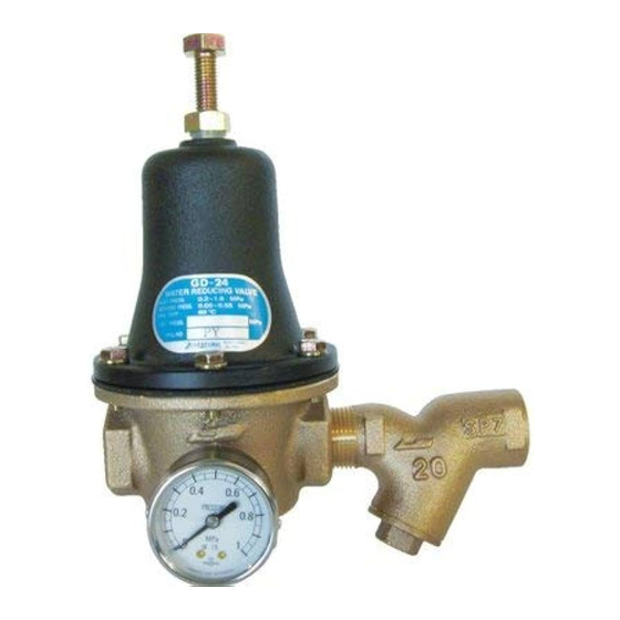
Pressure Reducing Valve
Installation & Operation Manual
Please read this manual thoroughly before using the pressure reducing valve, so that
you may do so correctly and safely.
Please carefully store this manual in a handy place.
- --- -The following safety symbols are used in this manual. -- -- -
This symbol indicates a potentially hazardous situation that, if not avoided,
Warning
could result in death or serious injury.
This symbol indicates a hazardous situation that, if not avoided, may result
Caution
in minor or moderate injury. ("Caution" may also be used to indicate other
unsafe practices or risks of property damage.)
1. Specifications ································································ 1
2. Dimensions and Construction
2.1 Dimensions and Weight ················································· 2~3
2.2 Construction ·································································· 4
3. Operation ··········································································· 4
4.1 Nominal Size Selection Chart ············································ 5
4.2 Flow Rate Characteristics Chart ········································ 6
4.3 Pressure Characteristics Chart ·········································· 6
5.1 Piping Example ······························································ 7
5.2 Warning and precaution on installation ························ 7~8
6.1 Warning and precaution on operation ································· 8
6.2 Adjustment Procedure ···················································· 8
7. Maintenance Procedure ························································· 9
7.2 Troubleshooting ···························································· 10
8. Exploded Drawing ······························································ 10
After Sales Service
Model GD-24GS
Contents
■ EPDT-175d■
Advertisement
Table of Contents

Related Manuals for Yoshitake GD-24GS


Summary of Contents for Yoshitake GD-24GS
-
Page 1: Table Of Contents
Model GD-24GS Pressure Reducing Valve Installation & Operation Manual Please read this manual thoroughly before using the pressure reducing valve, so that you may do so correctly and safely. Please carefully store this manual in a handy place. - --- -The following safety symbols are used in this manual. -- -- -... -
Page 2: Specifications
GD-24GS pressure reducing valve for water (Hereinafter so called pressure reducing valve) is an all-purpose valve suitable for various applications, such as water supply systems of general residential housing, high-rise buildings, industrial plants, and factory equipment. It can also be used to provide stable water pressure in high-rise apartment units, and for hilly areas where each house requires an individual water supply system. -
Page 3: Dimensions And Weight
2. Dimensions & Construction 2.1 Dimensions & Weight 【GD-24GS】 (mm) Nominal Weight size (kg) Rc 1/2 197.5 Rc 3/4 Rc 1 Rc 1 1/4 Rc 1 1/2 Rc 2 17.5 【GD-24】 (mm) Nominal Weight size (kg) Rc 1/2 41.5 Rc 3/4... - Page 4 【Pressure gauge】 【SY-24】 (mm) Screen Nominal Weight size (kg) Rc 1/2 R 1/2 0.25 Rc 3/4 R 3/4 0.35 Rc 1 0.55 Rc 1 1/4 R 1 1/4 1.00 Rc 1 1/2 R 1 1/2 1.44 Rc 2 2.90 ■ EPDT-175d■...
-
Page 5: Construction
2.2 Construction Name of parts Body (GD-24) Spring Chamber Valve (Disc) Valve Seat Suspension Metal Diaphragm Shell Diaphragm Spring Plate Adjusting Screw Lock Nut Spring Lock Washer Adjusting Spring O-ring Bolt Sealed Nut Spring Pressure Gauge Body (SY-24) Screen O-ring Label Spring Washer Caution... -
Page 6: Nominal Size Selection
4. Nominal Size Selection 4.1 Nominal Size Selection Chart (For Water) Nominal size ΔP: Inlet/reduced pressure differential (MPa) Note: *The Chart shown above is for a GD-24 valve without SY-24. *Considering such factors as noise and durability, a 2 m/s flow velocity within the pipe is ideal. -
Page 7: Flow Rate Characteristics Chart
4.2 Flow Rate Characteristics Chart 4.3 Pressure Characteristics Chart ■ EPDT-175d■... -
Page 8: Installation
5. Installation 5.1 Piping Example 5.2 Warning and precaution on installation Warning In case installing safety relief valve as safety device at outlet side, joint relief pipe at outlet of safety relief valve and guide it to safety place where steam can relief out. Caution ( 1 ) Do not disassemble the valve unreasonably. -
Page 9: Operating Procedure
Nominal size Fig.1 6. Operating Procedure 6.1 Warning and precaution on operation Warning ( 1 ) Do not touch directly to pressure reducing valve with bare hands after flowing hot fluids *Doing so may result in burns. ( 2 ) Before flow the hot fluids in the pipe line, make sure that the fluids will not cause the risks through the end of piping system and the pipes are connected tightly. -
Page 10: Maintenance Procedure
7. Maintenance Procedure Be aware of foreign materials because many of faults on pressure reducing valve are due to the existence of foreign materials. Please be reminded that our warranty does not cover damages caused by foreign materials at the customer site. Failure resulting from faulty pressure gauge, clogged strainer and leakage from by-pass stop valve are phenomena kindred to failure of pressure reducing valve. -
Page 11: Troubleshooting
7.2 Troubleshooting (Refer to the parts number in “2.2 Construction”) Problem Cause Countermeasure 1. Diaphragm (8) is damaged. 1. Replace the diaphragm (8). Reduced pressure 2. Foreign matter is embedded in 2. Disassemble and remove the exceeds prescribed the valve (4) and/or valve seat (5), foreign mater.
Need help?
Do you have a question about the GD-24GS and is the answer not in the manual?
Questions and answers