Table of Contents
Advertisement
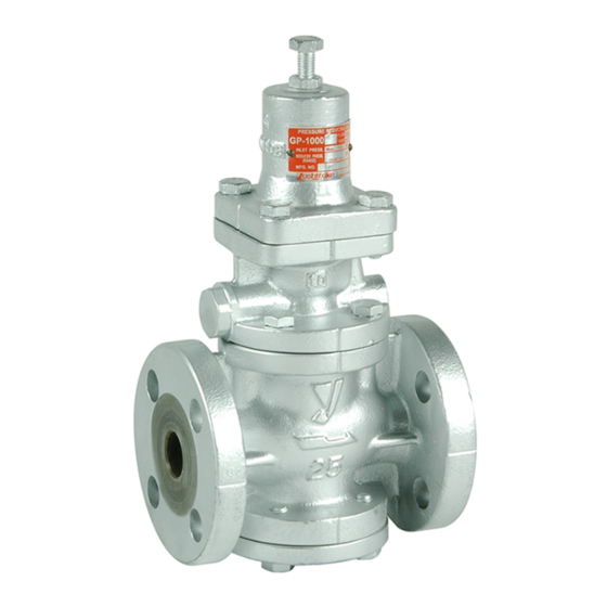
PRESSURE REDUCING VALVE
Please read this bulletin thoroughly before using the pressure reducing valve, so that you may
do so correctly and safely. Please carefully store this bulletin in a handy place.
---------The following safety symbols are used in this manual. --------
This symbol indicates a potentially hazardous situation that, if not
Warning
avoided, could result in death or serious injury.
This symbol indicates a hazardous situation that, if not avoided, may
Caution
result in minor or moderate injury. ("Caution" may also be used to
indicate other unsafe practices or risks of property damage.)
1. Features ・・・・・・・・・・・・・・・・・・・・・・・・・・・・・・・・・・・・・・・・・・・・・・・・・・・・・ 1
2. Specifications ・・・・・・・・・・・・・・・・・・・・・・・・・・・・・・・・・・・・・・・・・・・・・・・・ 1
3. Dimensions and Weights・・・・・・・・・・・・・・・・・・・・・・・・・・・・・・・・・・・・・ 2
4. Operation ・・・・・・・・・・・・・・・・・・・・・・・・・・・・・・・・・・・・・・・・・・・・・・・・・・・・ 3
5.1 Specifications selection chart ・・・・・・・・・・・・・・・・・・・・・・・・・・・・・ 4
5.2 Safety valve setting pressure ・・・・・・・・・・・・・・・・・・・・・・・・・・・・・ 4
5.3 Characteristics chart・・・・・・・・・・・・・・・・・・・・・・・・・・・・・・・・・・・・・・ 4
5.4 Nominal size selection chart ・・・・・・・・・・・・・・・・・・・・・・・・・・・・・・ 5
5.5 Nominal size selection calculation formula ・・・・・・・・・・・・・・・・ 6
6.1 Example of piping ・・・・・・・・・・・・・・・・・・・・・・・・・・・・・・・・・・・・・・・・ 6
6.2 Precautions during installation ・・・・・・・・・・・・・・・・・・・・・・・・・・・・ 7
7.1 Precautions during operation ・・・・・・・・・・・・・・・・・・・・・・・・・・・・・ 8
7.2 Adjustment procedures ・・・・・・・・・・・・・・・・・・・・・・・・・・・・・・・・・・・ 8
8.1 Troubleshooting ・・・・・・・・・・・・・・・・・・・・・・・・・・・・・・・・・・・・・・・・・・ 9
8.2 Precautions during maintenance and inspection ・・・・・・・・・ 10
8.3 Disassembly・・・・・・・・・・・・・・・・・・・・・・・・・・・・・・・・・・・・・・・・・・・・・ 10
8.4 Precautions during reassembly ・・・・・・・・・・・・・・・・・・・・・・・・・・ 11
8.5 Exploded drawing ・・・・・・・・・・・・・・・・・・・・・・・・・・・・・・・・・・・・・・・ 12
After Sale Service
Model GP-1000 Series
Installation & Operation Manual
Contents
■EPDT-081a■
Advertisement
Table of Contents

Related Manuals for Yoshitake GP-1000


Summary of Contents for Yoshitake GP-1000
-
Page 1: Table Of Contents
Model GP-1000 Series PRESSURE REDUCING VALVE Installation & Operation Manual Please read this bulletin thoroughly before using the pressure reducing valve, so that you may do so correctly and safely. Please carefully store this bulletin in a handy place. ―――――――――The following safety symbols are used in this manual. ――――――――... -
Page 2: Features
1. Features GP-1000 Series pressure reducing valves for steam are pilot-operated valves which can be used with confidence for small to large flow rate, in a host of applications ranging from building utilities systems, air-conditioning systems, and factory systems, etc. -
Page 3: Dimensions And Weights
3. Dimensions and Weights • GP-1000,1000H,1002 (㎜) L H H Size Weight(kg) 1 10.0 14.0 14.5 20.0 30.0 35.0 100A 52.5 • GP-1010,1012 (㎜) L H H Size Weight(kg) 1 Rc 1/2 Rc 3/4 Rc 1 Rc 1-1/4 12.0 Rc 1-1/2 12.5... -
Page 4: Operation
4. Operation Parts name Body Diaphragm Adjusting spring Adjusting screw Main valve Main valve seat Main valve spring Piston Cylinder Pilot valve Pilot valve seat Strainer Inlet press. passage Reduced press. Sensing port Diaphragm chamber The pressure-reducing valve reduces pressure by the throttling the valve. The valve is composed of the main valve and main valve seat for throttling, and adjusting spring, diaphragm, pilot valve, and piston for pressure sensing and activation. -
Page 5: Nominal Size Selection Method
5. Nominal Size Selection Method 5.1 Pressure reducing valve specification selection chart Find the intersection point of the inlet and reduced pressures. The GP-1000 series valves are suitable within range (A), (B), (C), and (D). ・Range(A) : GP-1000H ・Range(B) : GP-1000H、... -
Page 6: Nominal Size Selection Chart
5.4 Nominal size selection chart [Ex.1] For example, take a pressure reducing valve whose inlet pressure (P ) is 0.6 MPa, reduced pressure (P is 0.4 MPa, flow rate 800 kg/h. First, find the point of intersection (A) of inlet pressure 0.6 MPa and reduced pressure 0.4 MPa. -
Page 7: Nominal Size Selection Calculation Formula
5.5 Nominal size selection calculation formula The appropriate nominal size can be calculated by obtaining the Cv value for the operating conditions in question, as shown below. • Cv value calculation formula > W: Max. steam flow rate [kg/h] : Inlet pressure [MPa・A] : Reduced pressure [MPa・A] ∆... -
Page 8: Precautions During Installation
6.2 Precautions during installation Warning (1) Because of heavy weight, hold the valve with lifting equipment while piping. Refer to “3. Dimensions and weights” table for the valve weight. ※Failure to do so may result in injury due to dropping the valve. (2) In case installing safety valve as safety device at outlet side, joint relief pipe at outlet of safety valve and guide it to safety place where steam can relief out. -
Page 9: Operating Procedure
7. Operating Procedure 7.1 Precautions during operation Warning (1) Do not touch the valve directly with bare hands. ※Doing so may result in burns. (2) Before flow the steam in pipe line, make sure steam can flow without any dangerous at the end of pipe line and pipe line is connected tightly. -
Page 10: Maintenance Procedure
8. Maintenance Procedure 8.1 Troubleshooting Problem Cause Solution 1. Incorrect pressure is being used. 1. Correct the pressure. 2. Strainer [28] is clogged. 2. Disassemble and clean the strainer. 3. Foreign matter exists between 3. Disassemble and remove the foreign piston [14] and cylinder [15]. -
Page 11: Precautions During Maintenance And Inspection
8.2 Precautions during maintenance and inspection Warning (1)Completely discharge internal pressure from the valves, lines, and equipment, and cool the valve down to a level where you can touch it with bare hands before disassembly and inspection. ※Failure to do so may result in injury or burns due to residual pressure or spillage around the valve. -
Page 12: Precautions During Reassembly
8.4 Precautions during disassembly Caution (1) Check that there is no damage and scratches on the main valve, main valve seat, pilot valve, and pilot valve seat. ※ Any scratches at sealing surface lead to increase in secondary pressure. When any scratches are identified at main valve and seat, polish them away. -
Page 13: Exploded Drawing
8.5 Exploded drawing The parts from spring plate to top become as shown in the following figure for the model with handle. Diaphragm [5] and piston ring [16] are used two pieces for GP-1002 and GP-1012. Parts with in the flame are consumable. Please contact us for purchase of these consumable parts. №...
Need help?
Do you have a question about the GP-1000 and is the answer not in the manual?
Questions and answers