Table of Contents
Advertisement
Quick Links
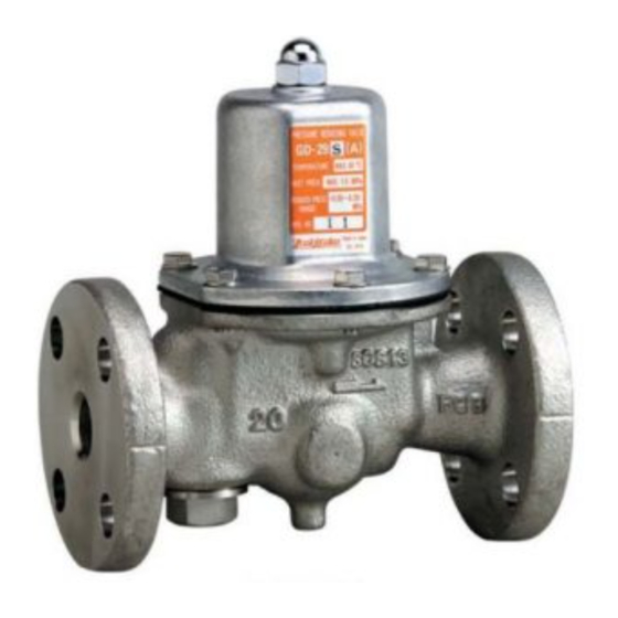
MODEL GD-26GS, GD-27GS
Pressure Reducing Valve
Thank you very much for choosing the Yoshitake's product. To ensure the correct and safe use of the product,
please read this manual before use. This manual shall be kept with care for future reference.
The symbols used in this manual have the following meanings.
Warning
Caution
Overview ····································································· 1
1. Feature ···································································· 1
3. Dimensions and weights ·········································· 5 - 6
4. Operation ································································· 7
6. Exploded view ···················································· 11 - 12
PRODUCT MANUAL
This symbol indicates a potentially hazardous situation that, if not avoided, could
result in death or serious injury.
This symbol indicates a hazardous situation that, if not avoided, may result in
minor or moderate injury or may result in only property damage.
2.1 Specifications ······················································ 1
2.2 Nominal size selection ······································ 2 - 3
2.3 Flow rate characteristics chart ································ 3
2.4 Pressure characteristics chart ································· 4
5.1 Precaution for operation ···································· 7 - 8
5.2 Warning and caution for operation ··························· 8
5.3 Piping example ···················································· 8
5.4 Adjusting procedure ·············································· 9
5.5 Troubleshooting ··················································· 9
5.6 Warning for disassembly and inspection ·················· 10
5.7 Disassembly ······················································ 10
Table of Contents
EPDT-089a
Advertisement
Table of Contents

Subscribe to Our Youtube Channel
Related Manuals for Yoshitake GD-26GS


Summary of Contents for Yoshitake GD-26GS
-
Page 1: Table Of Contents
Pressure Reducing Valve PRODUCT MANUAL Thank you very much for choosing the Yoshitake’s product. To ensure the correct and safe use of the product, please read this manual before use. This manual shall be kept with care for future reference. -
Page 2: Overview
2. Specifications (1) Please collate with attached nameplate and specification of ordered model. Caution ※Please consult factory in case they do not match each other. 2.1 Specifications Model GD-26GS GD-27GS Nominal size 20A - 50A 20A - 100A Application Air, Other non-dangerous fluids Inlet pressure 1.0 MPa or less... -
Page 3: Nominal Size Selection
2.2 Nominal size selection <For Air> ●Nominal size selection chart Nominal size [Example] When selecting the nominal size of a pressure reducing valve whose inlet pressure (P1), reduced pressure (P2), and flow rate are 0.3 MPa, 0.2 MPa, and 200 m /h (standard condition), respectively, first find intersection point (A) of the inlet pressure (P1) of 0.3 MPa and the reduced pressure (P2) of 0.2MPa. -
Page 4: Flow Rate Characteristics Chart
● Nominal size selection calculation formula • Cv value calculation formula > Q: Max. Fluid flow rate [m /h (standard condition)] : Inlet pressure [MPa・A] : Reduced pressure [MPa・A] ∆ 2940 ΔP: P -P [MPa] G: Specific gravity (Specific gravity per air) <... -
Page 5: Pressure Characteristics Chart
2.4 Pressure characteristics chart Inlet pressure MPa This chart shows variation in the reduced pressure when the inlet pressure of 0.60 MPa is changed between 0.15 MPa and 1.0 MPa after the reduced pressure is set at 0.10 MPa. EPDT-089a... -
Page 6: Dimensions And Weights
SUS303 Diaphragm shell Brass Retainer SUS304 Spring plate C3604 O-Ring Adjusting screw SUS416 Disc cover SUS304 Spring SWOSC-V Disc EPDM ● GD-26GS Nominal Weight size (kg) Rc 3/4 Rc 1 Rc 1 1/4 Rc 1 1/2 Rc 2 239.5 EPDT-089a... - Page 7 ● GD-27GS 20A-50A ● GD-27GS 65A-100A (mm) JIS 10K FF flanged Nominal Weight size (kg) n-φh 4-15 4-19 4-19 4-19 239.5 4-19 10.8 4-19 20.6 8-19 22.0 100A 8-19 34.5 EPDT-089a...
-
Page 8: Operation
4. Operation Adjusting The spring is compressed by the adjusting screw, screw the diaphragm is pushed down, and thereby the disc directly connected to it is opened. Spring Fluid coming in from the inlet side flows out from the upper part of the disc to the outlet side, and Diaphragm passes through the reduced pressure detection hole, and is led to the bottom of the diaphragm. -
Page 9: Warning And Caution For Operation
The set pressure may be affected by ambient temperature (external temperature) and fluid temperature. Install pipes so that the product may not be exposed to direct sunlight. 5.3 Piping example By-pass Globe valve Pressure gauge Safety valve Pressure gauge Stop Stop Inlet side valve GD-26GS valve Outlet side EPDT-089a... -
Page 10: Adjusting Procedure
5.4 Adjusting procedure Following a wrong adjusting procedure may cause hunting, scale problems or other problem, and can heavily damage the main parts of the valve. To avoid these problems, be sure to follow the procedure given below Close the stop valves at the inlet and outlet sides of the reducing valve, and take adequate time to blow out fluid by using a bypass line. -
Page 11: Warning For Disassembly And Inspection
5.6 Warning for disassembly and inspection Warning Completely discharge the pressure inside of the product, piping and equipment before disassembly and inspection. Disassembly and inspection must be done by experienced professional or valve manufacturer. * Failure to follow this notice may result in scalds, injury or contamination on the surroundings due to the residual pressure. -
Page 12: Exploded View
6. Exploded view Nominal size 20A - 50A EPDT-089a... - Page 13 Nominal size 65A-100A EPDT-089a...
Need help?
Do you have a question about the GD-26GS and is the answer not in the manual?
Questions and answers