Table of Contents
Advertisement
Quick Links
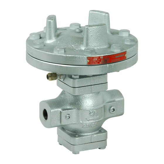
PRESSURE REDUCING VALVE
Thank you very much for choosing the Yoshitake's product. To ensure the correct and safe use of the
product, please read this manual before use. This manual shall be kept with care for future references.
The symbols used in this manual have the following meanings.
Warning
Caution
1. Specifications··························································· 1-2
2. Dimensions and Weights ············································· 2
3. Operation ································································ 3-5
4.2 Safety valve setting pressure chart ··························· 6
4.3 Characteristic chart ············································· 7
4.4 Nominal size selection chart ·································· 8
4.5 Nominal size selection calculation formula ················· 9
5.1 Precaution for installation ····································· 10
5.2 Installing accessories ·········································· 10
5.4 Piping example ·················································· 12
6.1 Precaution for operation ······································ 13
6.2 Adjusting procedure ············································ 13
7.1 Troubleshooting ················································· 14
7.2 Precaution for maintenance and inspection ·············· 15
7.3 Disassembly ····················································· 15
7.4 Precaution for reassembly ···································· 15
7.5 Exploded drawing ·············································· 16
MODEL GDK-2000
PRODUCT MANUAL
This symbol indicates a potentially hazardous situation that, if not avoided,
could result in death or serious injury.
This symbol indicates a hazardous situation that, if not avoided, may result
in minor or moderate injury or may result in only property damage.
Table of Contents
.
EPDT-021a
Advertisement
Table of Contents

Related Manuals for Yoshitake GDK-2000


Summary of Contents for Yoshitake GDK-2000
-
Page 1: Table Of Contents
PRESSURE REDUCING VALVE PRODUCT MANUAL Thank you very much for choosing the Yoshitake’s product. To ensure the correct and safe use of the product, please read this manual before use. This manual shall be kept with care for future references. -
Page 2: Specifications
1. Specifications Model GDK-2000 Screwed Flanged Connection JIS Rc JIS 20K RF JIS 10K FF Nominal size 15 ~ 50A 15 ~ 100A Application Steam Inlet pressure 0.1 ~ 2.0 MPa 0.1 ~ 1.0 MPa 0.05 ~ 1.4 MPa 0.05 ~ 0.9 MPa... -
Page 3: Dimensions And Weights
* Explanation of Chart Lines For a nominal size of 25A, the loading pressure for an inlet pressure [P ] of 1.0MPa and a reduced pressure[P ] of 0.2MPa can be obtained as follows: Find point[A] where a vertical line drawn upward from the valve’s inlet/reduced pressure differential (ΔP) (1.0 - 0.2 = 0.8MPa) intersects the 25A nominal size line. -
Page 4: Operation
3. Operation The pressure reducing valve reduces pressure by the throttling the valve. The valve is composed of the main valve, main valve seat, a pressure adjusting air chamber, and a main diaphragm for pressure sensing and activation. Parts name Body Main valve Main valve seat... - Page 5 (2) When air pressure is introduced into the air pressure control space [33] by a standard control unit, etc., main diaphragm [11] will bend and when it overcomes both the pressure against the back of the main valve, and the load of the main valve spring, thereby pushing the main valve open. The fluid then begins to flow from the inlet side to the reduced pressure side.
- Page 6 (4) In the absence of a reduced pressure load, the pressure in the diaphragm chamber increases, thereby pushing the main valve spring to close the valve. (Fig. 4) Air pressure Fig.4 EPDT-021a...
-
Page 7: Nominal Size Selection Method
4. Nominal size selection method 4.1 Pressure reducing valve specification selection chart To select the most appropriate pressure reducing valve, refer to the above selection chart. Find the intersection point of the inlet pressure (P ) and the reduced pressure (P ). -
Page 8: Characteristic Chart
4.3 Characteristic chart (1) Flow rate characteristics chart ● Shut-off pressure rise: 0.02 MPa or less ● Offset: 10% or less of set pressure at outlet side (Minimum value: 0.05MPa) (2) Pressure characteristics chart This chart shows variation in reduced pressure when the inlet pressure of 1.4 MPa is changed between 0.2 MPa and 1.4 MPa while the reduced pressure is set at 0.14 MPa. -
Page 9: Nominal Size Selection Chart
4.4 Nominal size selection chart [Example] When selecting the nominal size of a pressure reducing valve with its inlet pressure (P ) is 0.6 MPa, its reduced pressure (P ) is 0.4 MPa and its steam flow rate is 600 kg/h, first find the intersection point (a) of inlet pressure 0.6 MPa and reduced pressure 0.4 MPa. -
Page 10: Nominal Size Selection Calculation Formula
4.5 Nominal size selection calculation formula An appropriate nominal size can be calculated by obtaining Cv value for the operating conditions in question, as shown below. • Calculation formula for Cv value W: Max. steam flow rate [kg/h] : Inlet pressure [MPa・A] : Reduced pressure [MPa・A] ... -
Page 11: Installation
5. Installation 5.1 Precaution for installation Warning 1. Since the product is heavy, securely support it using lifting devices or the like when installing. See the product weight specified in “2. Dimensions and Weights”. * Failure to follow this notice may cause falling accident of the product, resulting in bodily injury. Caution 1. -
Page 12: Piping Before And After The Pressure Reducing Valve
5.3 Piping before and after the pressure reducing valve Warning 1. Be sure to install a non-return valve in the air line system. * Failure to do so could pose a risk of burns caused by steam flowing back through the air line in the event of the main diaphragm rupture. -
Page 13: Piping Example
5.4 Piping example The remote pressure reducing valve can set several levels of pressure with a single pressure reducing valve depending on how the pneumatic circuit for operation is constructed, and automatic control is possible with a solenoid valve. [Standard operating circuit] [Combination operation circuit] The standard unit's air pressure reducing Two sets of units are used, each of which... -
Page 14: Operation Procedure
6. Operation procedure 6.1 Precaution for operation Warning 1. Do not touch the product with bare hands directly. * Failure to follow this notice may result in scalds. 2. Before applying steam to the product, confirm that there is no risk when steam flows into the piping end and that piping joints are securely connected. -
Page 15: Maintenance Procedure
7. Maintenance Procedure 7.1 Troubleshooting (Refer to “7.5 Exploded drawing”) Trouble Cause Remedy 1. Working pressure is improper. 1. Correct the working pressure. 2. Insufficient operating air pressure. 2. Increase the operating air pressure to the desired set pressure. 3. The main diaphragm [11] is 3. -
Page 16: Precaution For Maintenance And Inspection
7.2 Precaution for maintenance and inspection Warning 1. Completely discharge the pressure inside of the product, piping and equipment prior to disassembly and inspection. When fluid is hot, cool down the product to the condition that it can be touched with bare hands. -
Page 17: Exploded Drawing
7.6 Exploded drawing The structure differs for nominal sizes 65A to 100A. The parts name shown in the rectangle boxes are available as consumable supply. * Apply lubricant agent for heat/steam resistance (recommendation: SOLVEST No.110 paste, STT Inc.) to the top and bottom seal area of the main diaphragm. EPDT-021a... -
Page 18: Warranty Information
( e.g. in case of corrosion due to outdoor use). Fire, flood, earthquake, thunder and other natural disasters. Consumable parts such as O-ring, gasket, diaphragm and etc. Yoshitake is not liable for any damage or loss caused by malfunction or defect of the product. PDD-046f...
Need help?
Do you have a question about the GDK-2000 and is the answer not in the manual?
Questions and answers