Table of Contents
Advertisement
SIREMOBIL Iso-C 3D
Installation Instructions
3D Reconstruction
Print No.: SPR2-230.814.01.05.02
Replaces: SPR2-230.814.01.04.02
SP
© Siemens AG 2001
The reproduction, transmission or
use of this document or its contents
is not permitted without express
written authority. Offenders will be
liable for damages. All rights,
including rights created by patent
grant or registration of a utility
model
_or_ design,_are_
reserved.
English
Doc. Gen. Date: 08.04
Advertisement
Table of Contents

Related Manuals for Siemens SIREMOBIL Iso-C 3D


Summary of Contents for Siemens SIREMOBIL Iso-C 3D
- Page 1 SIREMOBIL Iso-C 3D Installation Instructions 3D Reconstruction © Siemens AG 2001 The reproduction, transmission or use of this document or its contents is not permitted without express written authority. Offenders will be liable for damages. All rights, including rights created by patent...
- Page 2 Assemblers and other persons who are not employed by or otherwise directly affiliated with or autho- rized by Siemens or one of its affiliates are directed to contact one of the local offices of Siemens or one of its affiliates before attempting installation or service procedures.
-
Page 3: Table Of Contents
Cable no. 5B, item number n.a......4 - 6 Siemens AG SPR2-230.814.01 Page 3 of 6 SIREMOBIL Iso-C 3D Medical Solutions Rev. 05 08.04... - Page 4 Zipper hose ........6 - 38 Cable no. 12, item number n.a......6 - 39 SIREMOBIL Iso-C 3D SPR2-230.814.01...
- Page 5 7 _______4. Part of activities independent of serial number ____________________ 7 - 1 Checking the C-arm movements for SIREMOBIL Iso-C 3D ....7 - 1 Where to go from here....... . 7 - 1...
- Page 6 0 - 6 Contents Page SIREMOBIL Iso-C 3D SPR2-230.814.01 Page 6 of 6 Siemens AG Rev. 05 08.04 CS PS 24 Medical Solutions...
-
Page 7: Notes And Symbols
Siemens AG SPR2-230.814.01 Page 1 of 6 SIREMOBIL Iso-C 3D Medical Solutions Rev. 05 08.04 CS PS 24... -
Page 8: Safety Information
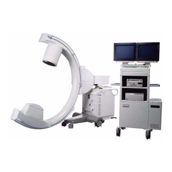
ARTD-002.731.17. • The protective conductor resistance must not exceed 0.2 ohms. WARNING Prior to performing the work, disconnect the power plug of the SIREMOBIL Iso-C. SIREMOBIL Iso-C 3D SPR2-230.814.01 Page 2 of 6 Siemens AG Rev. 05 08.04... - Page 9 This document describes the individual steps required to install the 3D option in the installed base - in this case the SIREMOBIL Iso-C (Fig. 1). Fig. 1 Overview of the SIREMOBIL Iso-C 3D • There are two different mechanical installations.
-
Page 10: Tools, Measuring Equipment And Auxiliary Devices
Drill by Fein 71 40 705 Crown bit 71 40 804 Drilling template n.a. * This material will be provided by the trained CSE SIREMOBIL Iso-C 3D SPR2-230.814.01 Page 4 of 6 Siemens AG Rev. 05 08.04 CS PS 24... -
Page 11: Check List Prior To Installing The 3D Option
Field Service Strategy). For serial numbers beginning with 1409 the option may be installed by a CSE trained in SIREMOBIL Iso-C 3D. A room suitable for the installation is available. The tools to be provided by the R.U. are available. - Page 12 1 - 6 General This page intentionally left blank. SIREMOBIL Iso-C 3D SPR2-230.814.01 Page 6 of 6 Siemens AG Rev. 05 08.04 CS PS 24 Medical Solutions...
-
Page 13: Cover Of The X-Ray Unit
Remove the protective conductor. Cover of the horizontal carriage If LITHOSTAR MODULARIS option is installed: After the installation of the SIREMOBIL Iso-C 3D upgrade, the NOTE external part of the docking plate must be reinstalled. Perform the installation and setting of the switches as described in the LITHOSTAR MODULARIS Service Instructions. -
Page 14: Cover Of The Cable Module
The drill has to be positioned upside down while you drill the holes. Secure the drill with the belt included in the drill kit. • Ensure that drill shavings do not drop into the cable module. SIREMOBIL Iso-C 3D SPR2-230.814.01 Page 2 of 14 Siemens AG Rev. -
Page 15: Drilling And Threading Holes For Installing The Limit Switches At The Cable Module
Cut the threads using an M4 thread tap (if required, use a drill with a left and right spiral (clockwise and counterclockwise) or a tap wrench). Siemens AG SPR2-230.814.01 Page 3 of 14 SIREMOBIL Iso-C 3D Medical Solutions Rev. 05 08.04 CS PS 24... -
Page 16: Cabling, Basic Unit
• Take off the tape (Fig. 8). • Remove the upper cable support (Fig. 9). • Move the lifting column into the top position. SIREMOBIL Iso-C 3D SPR2-230.814.01 Page 4 of 14 Siemens AG Rev. 05 08.04 CS PS 24... -
Page 17: Energy Chain
If in place, remove the tape (Scotch tape) on both sides of the energy chain (see Fig. 12). • Open the energy chain fully. Siemens AG SPR2-230.814.01 Page 5 of 14 SIREMOBIL Iso-C 3D Medical Solutions Rev. 05 08.04 CS PS 24... - Page 18 In case of blockage, pull the cables back a little, turn them and continue pulling them toward the top. • Pull the cables up to the mark. • Remove the two wires. SIREMOBIL Iso-C 3D SPR2-230.814.01 Page 6 of 14 Siemens AG Rev. 05 08.04...
- Page 19 Attach the cable cover. • Reattach the upper cable support. • Close the energy chain. • Move the lifting column into the lowest position. Siemens AG SPR2-230.814.01 Page 7 of 14 SIREMOBIL Iso-C 3D Medical Solutions Rev. 05 08.04 CS PS 24...
- Page 20 • Route the cables as shown in (Fig. 19, Fig. 20 and Fig. 21). • Do not stabilize the newly routed cables with the existing cables (e.g. with cable ties). SIREMOBIL Iso-C 3D SPR2-230.814.01 Page 8 of 14 Siemens AG Rev.
-
Page 21: Upgrade Cable Set, Item Number 71 39 996
Fig. 22 Emergency stop relay is mounted • Install the emergency stop relay as shown in Fig. 22. Use the two existing Allen screws for this purpose. Siemens AG SPR2-230.814.01 Page 9 of 14 SIREMOBIL Iso-C 3D Medical Solutions Rev. 05 08.04 CS PS 24... -
Page 22: Emergency Stop Circuit 71 39 988" Package
Connect plug M16.X20 to plug M16.X20 of the cable harness just installed. • At the main cable harness Plug M3.X30.1 into plug contact 1. Plug M3.X30.3 into plug contact 3. SIREMOBIL Iso-C 3D SPR2-230.814.01 Page 10 of 14 Siemens AG Rev. 05 08.04... -
Page 23: Cable No. 3 (Fig. 25)
Insert connector D200.X222 into X222 on pc boad D200 after it has been installed. • Insert the other end of the cable into contact 1 and 2 of the emergency stop relay M16.K1. Siemens AG SPR2-230.814.01 Page 11 of 14 SIREMOBIL Iso-C 3D Medical Solutions Rev. 05 08.04 CS PS 24... -
Page 24: Orbital Drive
Set the torque wrench to 8 Nm. • The opening at the cable module has to point upward for the installation of the connecting piece (C-arm angulation must be 90°). SIREMOBIL Iso-C 3D SPR2-230.814.01 Page 12 of 14 Siemens AG Rev. - Page 25 • Immediately remove any remaining Loctite to ensure that it does not touch the ball bearing! Siemens AG SPR2-230.814.01 Page 13 of 14 SIREMOBIL Iso-C 3D Medical Solutions Rev. 05 08.04 CS PS 24...
-
Page 26: Centering Disk, Item No. 71 40 580
Fig. 33 Individual parts Fig. 34 Centering disk, fully installed up to serial number 1408 • Attach the washer and the centering disk at the cable module (see Fig. 33 and Fig. 34). SIREMOBIL Iso-C 3D SPR2-230.814.01 Page 14 of 14 Siemens AG Rev. -
Page 27: Covers
Fig. 1 Fully installed centering disk, beginning with serial number 1409 • Attach the centering disk at the cable module (see Fig. 1). Siemens AG SPR2-230.814.01 Page 1 of 2 SIREMOBIL Iso-C 3D Medical Solutions Rev. 05 08.04 CS PS 24... - Page 28 3 - 2 Actions beginning with serial number 1409 This page intentionally left blank. SIREMOBIL Iso-C 3D SPR2-230.814.01 Page 2 of 2 Siemens AG Rev. 05 08.04 CS PS 24 Medical Solutions...
-
Page 29: C-Arm
1409" in chapter 3. C-arm Fig. 1 C-arm, starting position Fig. 2 Mark distance Fig. 3 Mark hole Fig. 4 Drill Siemens AG SPR2-230.814.01 Page 1 of 14 SIREMOBIL Iso-C 3D Medical Solutions Rev. 05 08.04 CS PS 24... - Page 30 Cut the threads using an M4 thread tap (e.g. use a tap wrench) (Fig. 5). • Attach the cam using 2 countersunk screws M 4 x 8 (Fig. 6). • Repeat these steps on the other side of the C-arm. SIREMOBIL Iso-C 3D SPR2-230.814.01 Page 2 of 14 Siemens AG Rev. 05 08.04...
-
Page 31: Limit Switches
Test the function of the limit switches by moving the C-arm into the +95° und -95° orbital positions. • Check these settings at least twice. Siemens AG SPR2-230.814.01 Page 3 of 14 SIREMOBIL Iso-C 3D Medical Solutions Rev. 05 08.04 CS PS 24... - Page 32 • Attach D200 with the contact washers and nuts (Fig. 14). Fig. 13 Bolt mounted, 3D reconstruction system electronics D200 Fig. 14 Installed 3D reconstruction system electronics D200 SIREMOBIL Iso-C 3D SPR2-230.814.01 Page 4 of 14 Siemens AG Rev. 05 08.04...
- Page 33 Kapitelüberschrift hier eintragen 4 - 5 Fig. 1 Fig. 15 Connectors D200 Siemens AG SPR2-230.814.01 Page 5 of 14 SIREMOBIL Iso-C 3D Medical Solutions Rev. 05 08.04 CS PS 24...
-
Page 34: Cable No. 3, Item Number N.a
Connect cable no 1. to plug D30.X4 on D30 and to plug D200.X214 on D200. Cable no. 6, item number n.a. • Connect cable no. 6 to plug D200.X220 on D200 and to D10.X12 on PC board D10. SIREMOBIL Iso-C 3D SPR2-230.814.01 Page 6 of 14 Siemens AG Rev. -
Page 35: Orbital Drive Cable Set, Item No. 71 39 970
- Insert plug D200.X116 into plug-in-location D200.X116 on PC board D200 . - Insert plug D200.X221 into plug-in-location D200.x221 on PC board D200. Siemens AG SPR2-230.814.01 Page 7 of 14 SIREMOBIL Iso-C 3D Medical Solutions Rev. 05 08.04 CS PS 24... -
Page 36: Cable No. 7, Item Number N.a. (Fig. 18)
Remove the nut and the toothed washer at the CAN connector on cable no. 7. • Pull the two cables through the nut and the toothed washer. • Pull the cable through the opening (Fig. 20). SIREMOBIL Iso-C 3D SPR2-230.814.01 Page 8 of 14 Siemens AG Rev. 05 08.04... - Page 37 Insert the connector housing and ensure that it fully locks into position. • Insert the connector housing D200.X1001 into plug-in-location D200.X1001 on PC board D200 and tighten it with screws. Siemens AG SPR2-230.814.01 Page 9 of 14 SIREMOBIL Iso-C 3D Medical Solutions Rev. 05 08.04 CS PS 24...
- Page 38 • Connect the "Strober" plug with the "Strober" plug of the main cable harness (Fig. 23). • Secure it in the system with cable ties as shown in Fig. 23. SIREMOBIL Iso-C 3D SPR2-230.814.01 Page 10 of 14 Siemens AG Rev.
-
Page 39: Additional Work With The Lithostar Modularis Option
- Plug the 2nd cable end with connector D200.X211 into D200.X211. - Skip the following section "Installing the new LITHOSTAR MODULARIS interface" and continue on page 5-1. Siemens AG SPR2-230.814.01 Page 11 of 14 SIREMOBIL Iso-C 3D Medical Solutions Rev. 05 08.04 CS PS 24... -
Page 40: Installing The New Lithostar Modularis Interface
To do this, drill open the hole until the step drill is immersed in the plate down to the mark shown in Fig. 26 (approx. 0.5 mm from the largest drilled diameter of 30 mm). • Drill slowly! (approx. 300 to 500 rpm). SIREMOBIL Iso-C 3D SPR2-230.814.01 Page 12 of 14 Siemens AG Rev. - Page 41 The connector is positioned centrally to the 28 mm hole, the lid opens downward. • Fasten the connector with holding plate using the screws and lock washers supplied (1/Fig. 28). Siemens AG SPR2-230.814.01 Page 13 of 14 SIREMOBIL Iso-C 3D Medical Solutions Rev. 05 08.04 CS PS 24...
- Page 42 The wiring diagram for the interface cable is attached in NOTE chapter 8. Please take the wiring diagram out of this document and file it in the system binder under Wiring Diagram. SIREMOBIL Iso-C 3D SPR2-230.814.01 Page 14 of 14 Siemens AG Rev. 05 08.04...
-
Page 43: Orbital Drive
Remove the two existing screws (Fig. 2). • Attach the motor using 2 countersunk Allen screws M 8 x 40 (Fig. 3 and Fig. 4). Siemens AG SPR2-230.814.01 Page 1 of 8 SIREMOBIL Iso-C 3D Medical Solutions Rev. 05 08.04 CS PS 24... -
Page 44: Coupling Unit
• Tighten the belt. On the opposite side of the belt tightener, it should be possible to press down the belt approx. 2 - 3 mm with your thumb (Fig. 7). SIREMOBIL Iso-C 3D SPR2-230.814.01 Page 2 of 8 Siemens AG Rev. - Page 45 Once the potentiometer is in this position, turn it fully clockwise twice. • Secure the belt pulley with the Allen screw (Fig. 10). Siemens AG SPR2-230.814.01 Page 3 of 8 SIREMOBIL Iso-C 3D Medical Solutions Rev. 05 08.04 CS PS 24...
-
Page 46: Drive Belt
• Tighten the drive belt . • Attach the counterbalancing weight for the C-arm. • Repeat the procedure on the other side of the C-arm. SIREMOBIL Iso-C 3D SPR2-230.814.01 Page 4 of 8 Siemens AG Rev. 05 08.04 CS PS 24... -
Page 47: Angulation Measurement
Move the angulation part into the cable module and attach it with screws (Fig. 17). Ensure that the markings (black lines) on the two gear wheels match exactly (Fig. 16). Siemens AG SPR2-230.814.01 Page 5 of 8 SIREMOBIL Iso-C 3D Medical Solutions Rev. 05 08.04 CS PS 24... -
Page 48: Wiring For The Orbital Drive
Connect the "angulation" plug of the cable for the angulation part with the "X4" plug of the orbital drive cable set. • Connect the "limit switch " plug of the limit switch cable with the "limit switch" plug of the orbital drive. SIREMOBIL Iso-C 3D SPR2-230.814.01 Page 6 of 8 Siemens AG Rev. 05 08.04... - Page 49 Clamp the red cable of the coupling unit to terminal block no. 3. • Clamp the blue cable of the coupling unit to terminal block no. 4. Siemens AG SPR2-230.814.01 Page 7 of 8 SIREMOBIL Iso-C 3D Medical Solutions Rev. 05 08.04 CS PS 24...
- Page 50 5 - 8 2. Part of activities independent of serial number This page intentionally left blank. SIREMOBIL Iso-C 3D SPR2-230.814.01 Page 8 of 8 Siemens AG Rev. 05 08.04 CS PS 24 Medical Solutions...
-
Page 51: Preparations On The Monitor Trolley
Remove the cover for the system manual drawer (Fig. 1). • Remove the cable ties. • Remove the front cover (Fig. 2). Siemens AG SPR2-230.814.01 Page 1 of 42 SIREMOBIL Iso-C 3D Medical Solutions Rev. 05 08.04 CS PS 24... -
Page 52: Replacing The Monitor
• Reattach all previously removed parts to the monitor. • Remove the 2 screws at the monitor mounting (Fig. 6). • Lift down the monitor. SIREMOBIL Iso-C 3D SPR2-230.814.01 Page 2 of 42 Siemens AG Rev. 05 08.04 CS PS 24... - Page 53 Unscrew and remove the base from the monitor trolley (Fig. 7). • Remove the video cable. • You do not need the monitor or the upper part of the base plate for SIREMOBIL Iso-C 3D. Siemens AG SPR2-230.814.01 Page 3 of 42 SIREMOBIL Iso-C 3D Medical Solutions Rev.
-
Page 54: Cable No. 13, Item Number N.a
/Fig. 11). They have to point toward the back of the monitor trolley. • Pull cable no. 13 (Fig. 8) through the monitor support. Pull cable downward and to the left (see Fig. 10). SIREMOBIL Iso-C 3D SPR2-230.814.01 Page 4 of 42 Siemens AG Rev. 05 08.04... - Page 55 H/H+V, red to V. • Connect the power plug of the old monitor to the new monitor. Siemens AG SPR2-230.814.01 Page 5 of 42 SIREMOBIL Iso-C 3D Medical Solutions Rev. 05 08.04 CS PS 24...
-
Page 56: Tft Displays
• Remove the two screws on each monitor attachment (Fig. 19). • Lift both monitors down. • Reattach all the parts removed from the monitor. SIREMOBIL Iso-C 3D SPR2-230.814.01 Page 6 of 42 Siemens AG Rev. 05 08.04 CS PS 24... - Page 57 Close the second cable opening on the side and the 8 fastening holes around the side cable openings with the dummy covers provided. Siemens AG SPR2-230.814.01 Page 7 of 42 SIREMOBIL Iso-C 3D Medical Solutions Rev. 05 08.04 CS PS 24...
- Page 58 NOTE On one end of the cable, the outer sheath of the new video cable is removed. Connect this cable end to the TFT display. SIREMOBIL Iso-C 3D SPR2-230.814.01 Page 8 of 42 Siemens AG Rev. 05 08.04...
- Page 59 Starting with the logbook compartment, tighten the screws of the support arm base on the monitor trolley. Use 4 Allen screws M6 x 20, 4 lock washers and 4 plate washers for this (Fig. 24). Siemens AG SPR2-230.814.01 Page 9 of 42 SIREMOBIL Iso-C 3D Medical Solutions Rev. 05 08.04 CS PS 24...
- Page 60 Setting the distances results in a distance of approx. 1 cm between the top and bottom edge of the TFT displays, on the one hand, and the tubes of the support arm, on the oth- er hand. SIREMOBIL Iso-C 3D SPR2-230.814.01 Page 10 of 42 Siemens AG Rev.
- Page 61 - Both tubes of the support arm should run in parallel to each other. Siemens AG SPR2-230.814.01 Page 11 of 42 SIREMOBIL Iso-C 3D Medical Solutions Rev. 05 08.04 CS PS 24...
- Page 62 6 - 12 3. Part of activities independent of serial number Fig. 29 Cabling of SIEMENS displays Fig. 30 Routing the cables Protective ground wiring of the support arm • On the support arm base of the TFT Display, a short protective ground wire is attached with stripped end.
- Page 63 • Reattach the cover of the support arm (Fig. 31). • When present, switch on the power switches of the TFT displays. Siemens AG SPR2-230.814.01 Page 13 of 42 SIREMOBIL Iso-C 3D Medical Solutions Rev. 05 08.04 CS PS 24...
-
Page 64: Pc Support
• Complete drilling the 4 holes by using a 6 mm drill bit. • Deburr the holes. • Remove the shavings. Use a vacuum cleaner, if needed. SIREMOBIL Iso-C 3D SPR2-230.814.01 Page 14 of 42 Siemens AG Rev. 05 08.04... - Page 65 • Attach the PC housing with the two mounting rails and the M 4 x 12 screws (Fig. 33 and Fig. 34). Siemens AG SPR2-230.814.01 Page 15 of 42 SIREMOBIL Iso-C 3D Medical Solutions Rev. 05 08.04 CS PS 24...
-
Page 66: Keyboard Tray
Draw the holes using the template. Ensure that the outer edge of the template lies flush with the back. • Punch-mark the holes. • Drill the holes with a 2.7 mm drill bit. SIREMOBIL Iso-C 3D SPR2-230.814.01 Page 16 of 42 Siemens AG Rev. 05 08.04... - Page 67 Pull out the inside tray of the keyboard tray. • Unscrew the spring steel cross bands in the back. • Loosen the rear transverse bar of the keyboard tray. Siemens AG SPR2-230.814.01 Page 17 of 42 SIREMOBIL Iso-C 3D Medical Solutions Rev. 05 08.04 CS PS 24...
- Page 68 Remove the tray again. • Punch-mark the hole. • Drill a 3.2 mm hole. • Deburr the holes. • Cut thread M4 (Fig. 44). SIREMOBIL Iso-C 3D SPR2-230.814.01 Page 18 of 42 Siemens AG Rev. 05 08.04 CS PS 24 Medical Solutions...
- Page 69 Fill the space on the other side with washers. • Tighten the tapping screws. • Reattach the rear transverse bar of the keyboard tray. Siemens AG SPR2-230.814.01 Page 19 of 42 SIREMOBIL Iso-C 3D Medical Solutions Rev. 05 08.04 CS PS 24...
- Page 70 Fig. 50 Partial view of adjusted keyboard tray Fig. 51 Adjusted keyboard tray • After sucessful adjustments, the keyboard tray should be identical with the (Fig. 49 and Fig. 50). SIREMOBIL Iso-C 3D SPR2-230.814.01 Page 20 of 42 Siemens AG Rev. 05 08.04...
- Page 71 - by pressing on both sides along the outside of the tray - by pushing against the center of the keyboard tray. • Attach the protective conductor to the protective conductor bar. Siemens AG SPR2-230.814.01 Page 21 of 42 SIREMOBIL Iso-C 3D Medical Solutions Rev. 05 08.04 CS PS 24...
-
Page 72: Rear Panel Of The Monitor Trolley
Fig. 58 PC installed • Remove the PC from the packaging. • Position the PC in the support (Fig. 56) and secure it with tape (Fig. 57). SIREMOBIL Iso-C 3D SPR2-230.814.01 Page 22 of 42 Siemens AG Rev. 05 08.04... -
Page 73: Video Switcher
Install (Fig. 58) the two video switchers (Fig. 61). You won’t need the power cables included in the package for the video switchers. Siemens AG SPR2-230.814.01 Page 23 of 42 SIREMOBIL Iso-C 3D Medical Solutions Rev. 05 08.04 CS PS 24... - Page 74 6 - 24 3. Part of activities independent of serial number Fig. 63 Video switcher, prior to cabling • Place the installed video switcher in the monitor trolley (Fig. 62). SIREMOBIL Iso-C 3D SPR2-230.814.01 Page 24 of 42 Siemens AG Rev. 05 08.04...
-
Page 75: Cut-Off Delay D210, Item No. 71 40 071
Fig. 67 Side view of installed D210 • Attach the D210 cut-off delay(Fig. 64) on the support (Fig. 66). • Secure it with toothed washers and nuts. Siemens AG SPR2-230.814.01 Page 25 of 42 SIREMOBIL Iso-C 3D Medical Solutions Rev. 05 08.04 CS PS 24... - Page 76 CAN-Port SCSI adapter (Memoskop) Relais board SCSI adapter (internal Harddisk + CD burner) Fig. 68 Back view of reconstruction PC SIREMOBIL Iso-C 3D SPR2-230.814.01 Page 26 of 42 Siemens AG Rev. 05 08.04 CS PS 24 Medical Solutions...
-
Page 77: Cabling Of The Mouse And Keyboard
Connect the video cable (has already be routed downward) from the monitor to input G at video switcher 1 (see Fig. 69). Siemens AG SPR2-230.814.01 Page 27 of 42 SIREMOBIL Iso-C 3D Medical Solutions Rev. 05 08.04 CS PS 24... - Page 78 Connect the 5 monitor cables at input 2 of video switcher 1 (see Fig. 69) - red to R; geen to G; blue to B; white to H; black to V. • Slide the excess cable into the side panel. SIREMOBIL Iso-C 3D SPR2-230.814.01 Page 28 of 42 Siemens AG Rev.
-
Page 79: Cable, No. 10, Item Number N.a
Insert the VGA plug (Fig. 58) into the left graphics card. • Connect the Video Out plug with BNC coupling/ Cinch (see Fig. 73). Siemens AG SPR2-230.814.01 Page 29 of 42 SIREMOBIL Iso-C 3D Medical Solutions Rev. 05 08.04 CS PS 24... -
Page 80: Cable No. 14, Item Number N. A
(see Fig. 69) . • Route the other plug down to the Memoskop and insert it into Out3. • Slide the excess cable into the side panel. SIREMOBIL Iso-C 3D SPR2-230.814.01 Page 30 of 42 Siemens AG Rev. 05 08.04... -
Page 81: Scsi Cable, No. .N.a., Item Number 30 66 180
Connect plug A (see Fig. 75) with plug location "SCSI" at the Memoskop and lock it into position. • Connect plug B (see Fig. 75) with PC plug location "SCSI Adapter" and secure it with screws. Siemens AG SPR2-230.814.01 Page 31 of 42 SIREMOBIL Iso-C 3D Medical Solutions Rev. 05 08.04 CS PS 24... -
Page 82: Cable No. 11, Item Number N.a
If there is no printer, connect the ’Printer Remote’ plug with the Memoskop coupling. If required, insulate the metal housing with tape. • Plug D100.X1001 is not connected. Insulate the contacts, roll up the cable and attach it using cable ties. SIREMOBIL Iso-C 3D SPR2-230.814.01 Page 32 of 42 Siemens AG Rev. 05 08.04... -
Page 83: Cable No. 15, Item Number N.a
Insert plug D210.X1 into pc board D210.X1. • Disconnect plug X5 from D50 and insert it into D210.X2. • Insert plug D50.X5 into switch-on circuit D50.X5. Siemens AG SPR2-230.814.01 Page 33 of 42 SIREMOBIL Iso-C 3D Medical Solutions Rev. 05 08.04 CS PS 24... -
Page 84: Cable No. 16, Item Number N.a
• Connect 1 cable outlet (siehe Fig. 80) at video switcher 2 (siehe Fig. 69). * If this is not possible, route the 2 cable outlets from the bottom to the top. SIREMOBIL Iso-C 3D SPR2-230.814.01 Page 34 of 42 Siemens AG Rev. - Page 85 Connect the blue cable end to terminal 2 of terminal block X2 (siehe Fig. 82). • Connect the green/yellow cable end to the protective conductor bar (siehe Fig. 82). Siemens AG SPR2-230.814.01 Page 35 of 42 SIREMOBIL Iso-C 3D Medical Solutions Rev. 05 08.04 CS PS 24...
-
Page 86: Cables No. 8 And 9, Item Number N.a
(siehe Fig. 84) and secure it with screws. • The "Navigation" plug is currently not in use. The connection for this plug is described separately in the document "Navigation start-up". SIREMOBIL Iso-C 3D SPR2-230.814.01 Page 36 of 42 Siemens AG Rev. -
Page 87: Attaching The Video Switcher
Attach the video switchers with 4 tapping screws 3.5 x 16 (see Fig. 87 and Fig. 88). System manual drawer • Reattach the front cover to the drawer. Siemens AG SPR2-230.814.01 Page 37 of 42 SIREMOBIL Iso-C 3D Medical Solutions Rev. 05 08.04 CS PS 24... -
Page 88: Zipper Hose
Route the zipper hose underneath the connection cable and cable no. 8. • Use the "zipper pliers" to close the hose. • Secure the ends with tape. SIREMOBIL Iso-C 3D SPR2-230.814.01 Page 38 of 42 Siemens AG Rev. 05 08.04... -
Page 89: Cable No. 12, Item Number N.a
Attach it with 2 tapping screws (Fig. 91). • Connect the PS2 plug to the "Secondary Pointing Device" plug-in-location on the mouse port adapter. Siemens AG SPR2-230.814.01 Page 39 of 42 SIREMOBIL Iso-C 3D Medical Solutions Rev. 05 08.04 CS PS 24... -
Page 90: External Mouse
Insert the dongle at the printer port and secure it with screws. Cabling Fig. 93 Cabling Fig. 94 Cabling • Route the cables as shown in Fig. 92 and 93 and secure them with cable ties. SIREMOBIL Iso-C 3D SPR2-230.814.01 Page 40 of 42 Siemens AG Rev. 05 08.04... -
Page 91: Covers
Attach the rear panel of the monitor trolley. 3D label Fig. 97 3D label • Affix the 3D label to the monitor (Fig. 96). Siemens AG SPR2-230.814.01 Page 41 of 42 SIREMOBIL Iso-C 3D Medical Solutions Rev. 05 08.04 CS PS 24... - Page 92 Affix the safety label to the cover of the cable module as shown in Fig. 98. Also affix the second safety label to the cover of the cable module on the opposite side of the other label. SIREMOBIL Iso-C 3D SPR2-230.814.01 Page 42 of 42 Siemens AG Rev.
-
Page 93: Checking The C-Arm Movements For Siremobil Iso-C 3D
"normal" movement of a C-arm. If not, verify that connector M3.X1 for the brake assembly is inserted correctly. If yes, the LEDs in both keys light up. Where to go from here Continue with the SIREMOBIL Iso-C 3D Start-up Instructions SPR2-230.815.01..Siemens AG SPR2-230.814.01... - Page 94 7 - 2 4. Part of activities independent of serial number This page intentionally left blank. SIREMOBIL Iso-C 3D SPR2-230.814.01 Page 2 of 2 Siemens AG Rev. 05 08.04 CS PS 24 Medical Solutions...
- Page 95 Appendix 8 - 1 Fig. 1 Siemens AG SPR2-230.814.01 Page 1 of 2 SIREMOBIL Iso-C 3D Medical Solutions Rev. 05 08.04 CS PS 24...
- Page 96 8 - 2 Appendix This page intentionally left blank. SIREMOBIL Iso-C 3D SPR2-230.814.01 Page 2 of 2 Siemens AG Rev. 05 08.04 CS PS 24 Medical Solutions...
- Page 97 Cover page, contents and rev. level newly generated Chap. 6 TFT display installation expanded. Errors in PC display corrected. Numbering of figures updated. Siemens AG SPR2-230.814.01 Page 1 of 2 SIREMOBIL Iso-C 3D Medical Solutions Rev. 05 08.04 CS PS 24...
- Page 98 9 - 2 Changes to previous version This page intentionally left blank. SIREMOBIL Iso-C 3D SPR2-230.814.01 Page 2 of 2 Siemens AG Rev. 05 08.04 CS PS 24 Medical Solutions...
Need help?
Do you have a question about the SIREMOBIL Iso-C 3D and is the answer not in the manual?
Questions and answers