Table of Contents
Advertisement
Quick Links
Operator and Service Manual
48' L x 8'-6" W x 13'-6" H USA Unit
This manual contains confidential information of AMST. You may not copy it or any part of it without
This manual may be used only by you, and only for the purposes for which it was intended. You
may not disclose this manual or the confidential information it contains outside of your company.
If you wish to copy any part of this manual, or to use it other than as described above, you must
North America
Corporate Headquarters
AMST
611 Commerce Center Drive
University Park, Illinois
60484
USA
(001) 708-235-2800
(001) 708-235-2002 FAX
The information contained in this booklet is the property of AMST. The contents are confidential. They may not be used,
either partially or wholly, for any purpose inconsistent with the purpose for which it was produced. The contents may not be
reproduced or disclosed without written permission of Advanced Mobility Specialty Vehicles.
Siemens Viato 1.5T
Mobile MRI Systems
© 2024 AMST, All Rights Reserved.
the written permission of AMST.
contact AMST seeking permission to do so.
Europe
Advanced Mobility Specialty Vehicles, Ltd.
Unit 17, Nelson Way
Tuscum Trading Estate,
Camberley, Surrey
GU15 3DH
United Kingdom
(44) 01276.64490
Buys Ballotstraat 6
3261 LA Oud-Beijerland, Holland
+31 (0) 186-619367
Fax +31 (0) 186-619367
E-mail: smit@smit-mobile.nl
Page 1 of 140
SMRVI-D01-00
Advertisement
Table of Contents

Related Manuals for Siemens Magnetom Viato Mobile


Summary of Contents for Siemens Magnetom Viato Mobile
- Page 1 Page 1 of 140 SMRVI-D01-00 Operator and Service Manual Siemens Viato 1.5T Mobile MRI Systems 48’ L x 8’-6” W x 13’-6” H USA Unit © 2024 AMST, All Rights Reserved. This manual contains confidential information of AMST. You may not copy it or any part of it without the written permission of AMST.
- Page 2 Page 2 of 140 SMRVI-D01-00 As part of Advanced Mobility Specialty Vehicles’ on-going program to improve its products and service, (and their effectiveness in enhancing safety, reliability, performance, productivity, and the useful service life of the equipment) Advanced Mobility Specialty Vehicles reserves the right to implement product changes and disseminate changes in design and service information without notice or recourse.
-
Page 3: List Of Revisions & Warnings
Page 3 of 140 SMRVI-D01-00 List of Revisions & Warnings Revisions Date Issue Revised By Description 1/8/2024 Robert O'Connor Preliminary – Need to updated photos prior to unit shipment 3/18/2024 Ben Bartasiunas Updated Photos Notice In accordance with our policy of product development, Advanced Mobility Specialty Vehicles reserves the right to make changes in the equipment, design, specifications, and materials of the product described herein. -
Page 4: Warnings & Safety Alert Conventions
Page 4 of 140 SMRVI-D01-00 Warnings & Safety Alert Conventions The following terms define the various precautions and notices used in this manual: Whenever information exists that requires additional emphasis beyond the NOTE: standard textual information, the term “NOTE” is used. Whenever information exists that requires special attention to procedures and/or is required by the Medical System OEM to ensure proper operation of the equipment or to prevent its possible failure, the term “IMPORTANT”... -
Page 5: Table Of Contents
Page 5 of 140 SMRVI-D01-00 Table of Contents List of Revisions & Warnings ................3 Revisions ............................3 Warnings & Safety Alert Conventions ..................... 4 Table of Contents ....................5 List of Figures ..................... 10 Section 1: Introduction .................. - Page 6 Page 6 of 140 SMRVI-D01-00 4.6.4 Power Supply Unit ......................44 4.6.5 Printed Circuit Board ......................45 4.6.6 Operator Interface ......................46 4.6.7 LED Indicators ........................46 4.6.8 Control Switches ....................... 47 4.6.9 Digital Display ........................47 ...
- Page 7 Page 7 of 140 SMRVI-D01-00 5.12.3 Waste Water Connections (sink option) ................. 63 5.13 Remove Restraining Hardware ..................... 63 5.14 Prepare the Medical System per OEM Instructions .............. 64 5.15 Canopy Deployment (if applicable) ..................64 Section 6: Mobile Unit Transport Procedure ............
- Page 8 Page 8 of 140 SMRVI-D01-00 10.1.3 Lift Up Indicator Light ...................... 94 10.1.4 Remote Control Pendent ....................94 10.1.5 Transport Warning Light ....................95 10.2 Hydraulic System ......................95 10.2.1 Operation ........................95 10.3 Platform lift Operation ....................
- Page 9 Appendix E: Lockout/Tagout Procedures ............131 Specific Energy Control Procedures ................... 131 Specialty Vehicle Trailer: Siemens Aera MRI System ..............131 Appendix F: Coil Storage ................. 133 Appendix G: Quarterly Maintenance Checklist ..........135 ...
-
Page 10: List Of Figures
Page 10 of 140 SMRVI-D01-00 List of Figures Figure 1: The Siemens Viato Mobile MRI System ................12 Figure 2: Air Ride Control Valves ...................... 18 Figure 3: Canopy ..........................19 Figure 4: Control Room Overall ......................20 ... - Page 11 Page 11 of 140 SMRVI-D01-00 Figure 50: Platform Storage & Safety Latches ................. 93 Figure 51: Remote Control Pendent ....................94 Figure 52: Landing / Stabilizing Leg Assembly ................. 98 Figure 53: Air Bag Controls ....................... 99 ...
-
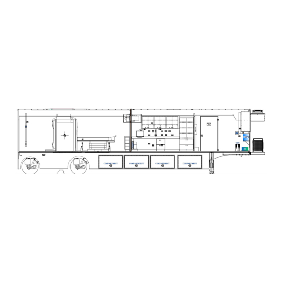
Page 12: Section 1: Introduction
The drawings in this manual are representative of this product. Figure 1: The Siemens Viato Mobile MRI System In accordance with our program of continued product development, designs and specifications are subject to change without notice. - Page 13 Page 13 of 140 SMRVI-D01-00 As part of Advanced Mobility Specialty Vehicles’ on-going program to improve its products and service, (and their effectiveness in enhancing safety, reliability, performance, productivity, and the useful service life of the equipment) Advanced Mobility Specialty Vehicles reserves the right to implement product changes and disseminate changes in design and service information without notice or recourse.
-
Page 14: Section 2: Safety Guidelines
Page 14 of 140 SMRVI-D01-00 Section 2: Safety Guidelines Electrical, mechanical, pneumatic, and hydraulic safety devices have been installed on this vehicle to help protect against personal injury and / or damage to equipment. Under no circumstances should any attempt be made to disconnect or in any way render any of these devices inoperative. -
Page 15: Operator's General Safety Precautions
Page 15 of 140 SMRVI-D01-00 2.1 Operator’s General Safety Precautions Your safety and the safety of other persons in the area of this vehicle are the result of your correct operation of this vehicle. Know the location, positions, and functions of all the controls. Know the meaning of the various Warning, Caution, Strobe, and Annunciator lights and their associated audible warning sounds. -
Page 16: Chemical Safety
Page 16 of 140 SMRVI-D01-00 2.3 Chemical Safety When working in the presence of liquid helium, make sure the work area is well ventilated. Inhalation of helium or nitrogen can cause rapid suffocation. If any personnel inhale gas, quickly move them to fresh air and seek medical attention at once. ... -
Page 17: Transportation Safety
The owner/operator must notify Siemens Magnet Technology within one (1) day of any instance that causes the shock logger alarm to sound. Failure to do so could result in invalidating the Siemens Magnet Technology warranty. Contact the local Siemens Medical Systems Representative. -
Page 18: Section 3: Mobile Unit Overview
Page 18 of 140 SMRVI-D01-00 Section 3: Mobile Unit Overview The components of the mobile unit have been divided into alphabetical order. With each component a picture and description will be found to better illustrate the components of the mobile unit. -
Page 19: Canopy (Optional)
Page 19 of 140 SMRVI-D01-00 3.2 Canopy (optional) This retractable canopy is positioned above the platform lift to provide shelter from the elements. The handle used to deploy the unit is neatly stowed in Equipment Room during transit. Figure 3: Canopy The information contained in this booklet is the property of AMST. -
Page 20: Control Room Overall
Page 20 of 140 SMRVI-D01-00 3.3 Control Room Overall Control Room houses the controls for the technician. The internal environment of the mobile unit can be monitored from Control Room. Figure 4: Control Room Overall Figure 5: Advanced Mobility System ID Tag & Job Number The information contained in this booklet is the property of AMST. -
Page 21: Cryogen Compressor
Page 21 of 140 SMRVI-D01-00 3.4 Cryogen Compressor The cryogen compressor is supplied by Siemens. For information regarding the cryogen compressor, please refer to the manuals supplied by Siemens. Figure 6: Cryogen Compressor Cabinet The information contained in this booklet is the property of AMST. The contents are confidential. They may not be used, either partially or wholly, for any purpose inconsistent with the purpose for which it was produced. -
Page 22: Exterior Overall
Page 22 of 140 SMRVI-D01-00 3.5 Exterior Overall In these pictures the hydraulic platform lift, the staff entry door, the generator housing, the HVAC unit and the emergency exit / service entry door to Equipment Room can be seen. Right Side Figure 7: Exterior Overall Left Side The information contained in this booklet is the property of AMST. -
Page 23: Equipment Room Overall
Page 23 of 140 SMRVI-D01-00 3.6 Equipment Room Overall Equipment Room houses the system components that support the medical system, such as the humidifier and water tank, and the main electrical panels. Figure 8: Equipment Room Overall The information contained in this booklet is the property of AMST. The contents are confidential. They may not be used, either partially or wholly, for any purpose inconsistent with the purpose for which it was produced. -
Page 24: Exterior Staff Entry Door
Page 24 of 140 SMRVI-D01-00 3.7 Exterior Staff Entry Door A 44” inch wide, high quality, positive latching, double gasket, insulated main entry door with door closer and tinted glass window is installed on the mobile unit. The door is fitted with hospital grade emergency exit bar and an adjustable privacy blind on the window. -
Page 25: Fuel Compartment
Page 25 of 140 SMRVI-D01-00 3.8 Fuel Compartment The fuel compartment stores the fuel tank, fuel gauge, fuel pump, and fuel separator. Figure 10: Fuel Compartment Fuel Gauge: The fuel gauge is push button activated and will give an accurate reading of the available fuel supply. -
Page 26: Glad-Hand Connections
Page 26 of 140 SMRVI-D01-00 3.10 Glad-hand Connections The glad hands are the connection point between the tractor and the mobile unit. All connections must be made before moving the mobile unit. Failure to make all connections can result in damage to the mobile unit. -
Page 27: Hubbell All Weather Phone Cables
Page 27 of 140 SMRVI-D01-00 3.11 Hubbell All Weather Phone Cables Hubbell all weather phone cables are required for use with the Hubbell all weather phone connections. Figure 13: Hubbell All Weather Phone Cables The information contained in this booklet is the property of AMST. The contents are confidential. They may not be used, either partially or wholly, for any purpose inconsistent with the purpose for which it was produced. -
Page 28: Levels
Page 28 of 140 SMRVI-D01-00 3.12 Levels The levels allow the mobile unit to be leveled both front to back and side to side. It is imperative that the unit be leveled prior to use. Figure 14: Levels Bubble Levels The information contained in this booklet is the property of AMST. -
Page 29: Magnet Room
Page 29 of 140 SMRVI-D01-00 3.13 Magnet Room The Magnet Room is located at the rear of the magnet and is accessible from the rear service entrance door. This room is provided as a service area at the rear of the magnet. Figure 15: Magnet Room Helium Rear Door The information contained in this booklet is the property of AMST. - Page 30 Page 30 of 140 SMRVI-D01-00 Page intentionally left blank The information contained in this booklet is the property of AMST. The contents are confidential. They may not be used, either partially or wholly, for any purpose inconsistent with the purpose for which it was produced. The contents may not be reproduced or disclosed without written permission of Advanced Mobility Specialty Vehicles.
-
Page 31: Mobile Unit Controls
Page 31 of 140 SMRVI-D01-00 3.14 Mobile Unit Controls Located inside of the mobile unit are the various controls that are used for operating such items as the interior and exterior lights, the hydraulic platform lift, warning lights, emergency stop buttons, fire alarms, and emergency equipment. - Page 32 Page 32 of 140 SMRVI-D01-00 Platform lift Warning Light: Notifies the operator of the hydraulic platform lift position status. Scan Room Light Switches: High/Low light switch for Scan Room and Magnet Room. The information contained in this booklet is the property of AMST. The contents are confidential. They may not be used, either partially or wholly, for any purpose inconsistent with the purpose for which it was produced.
-
Page 33: Phone & Data Line Connections
Page 33 of 140 SMRVI-D01-00 3.15 Phone & Data Line Connections The phone and data connections are located in the underbody compartments. The connections are used to connect the mobile unit to the shore facility. The telephone connections utilize a Hubbell all weather connection, while the data lines utilize an RJ-45 connection and CAT-6E cabling. -
Page 34: Scan Room Overall
Page 34 of 140 SMRVI-D01-00 3.16 Scan Room Overall Scan Room houses the medical equipment system. Also located in this room are storage compartments for the medical equipment. Placed alongside the storage compartments the magnet quench button can be found. In the Magnet Room the emergency shutdown button can be found. Figure 18: Scan Room Overall The information contained in this booklet is the property of AMST. -
Page 35: Stabilizing Stands
Page 35 of 140 SMRVI-D01-00 3.17 Stabilizing Stands The stabilizing stands are placed underneath the rear of the mobile unit when the medical system is in use. These stands help to level the mobile unit and decrease vibration, which can affect scan quality. -
Page 36: Stair Assembly
Page 36 of 140 SMRVI-D01-00 3.18 Stair Assembly The stairs allow access to the interior of the mobile unit through the staff door. When assembling the stairs, please refer to the following illustrations. Figure 20: Stair Assembly (standard) The maximum capacity of the stairs or platform in any combination is 375 pounds. -
Page 37: Water / Wastewater Connections (Sink Option)
Page 37 of 140 SMRVI-D01-00 3.19 Water / Wastewater Connections (Sink Option) The fresh water and wastewater connections are located in the front of the trailer under the mobile unit. Please refer to the following illustration. Figure 21: Fresh Water and Wastewater Connections The information contained in this booklet is the property of AMST. -
Page 38: Section 4: Safety Systems
Page 38 of 140 SMRVI-D01-00 Section 4: Safety Systems This safety section contains important information about the safety systems that have been built into the mobile unit to protect all personnel and equipment. Before attempting to service the mobile unit, read this safety section as well as all other safety sections found in applicable manufacturers’ manuals in the VOL II Vendor Information binder. -
Page 39: Service Door Equipment Room
Page 39 of 140 SMRVI-D01-00 4.2 Service Door Equipment Room A service door has been installed on the street sidewall of the mobile unit. This door is used for loading equipment in and out of the trailer. Figure 23: Service Door The information contained in this booklet is the property of AMST. -
Page 40: Emergency Lighting
Page 40 of 140 SMRVI-D01-00 4.3 Emergency Lighting In the event that the main AC power fails, a single beam emergency light is provided. This light will automatically illuminate when the main AC power is lost. It is located in the Control Room. -
Page 41: Fire Detection System (Optional)
Page 41 of 140 SMRVI-D01-00 4.5 Fire Detection System (optional) The fire alarm control panel is responsible for monitoring the fire alarm system. Located on the interior of the fire control panel is a brief list of instructions that explain how to use the system control buttons to test, reset, and silence the alarm. -
Page 42: Pull Station
Page 42 of 140 SMRVI-D01-00 During normal operation, the control unit remains in a supervisory mode. If one smoke detector goes into alarm, it will trigger the following actions. The fire horn will sound continuously. A (RED) alarm LED located on the front cover of the fire system control panel will illuminate. -
Page 43: Novec-1230 Fire Suppression System (Optional)
Page 43 of 140 SMRVI-D01-00 4.6 NOVEC-1230 Fire Suppression System (Optional) An optional fire suppression system is available for the mobile unit. This fire suppression system uses a dispersant to extinguish the fire. The dispersant used is a gas that removes the oxygen from the interior of the mobile unit. -
Page 44: Control Unit Description
Page 44 of 140 SMRVI-D01-00 4.6.1 Control Unit Description The Fenwal 732 consists of the following: Enclosure with Door, Power Supply Unit, Printed Circuit Board (PCB), and Secondary Standby Batteries. 4.6.2 Enclosure with Door The enclosure meets the requirements for NEMA Type 1 and is intended to be used indoors in a relatively dust-free environment. -
Page 45: Printed Circuit Board
Page 45 of 140 SMRVI-D01-00 4.6.5 Printed Circuit Board The printed circuit board provides an interface or terminals for the following: Power Supply Unit Battery Initiating Device Circuits (System Inputs) System Outputs Operator Interface Auxiliary Power Output Figure 30: Printed Circuit Board (PCB) The information contained in this booklet is the property of AMST. -
Page 46: Operator Interface
Page 46 of 140 SMRVI-D01-00 4.6.6 Operator Interface All alarms, troubles and supervisory signals are received at the control unit and displayed for the operator. The Operator Interface consists of four main components and are visible and/or audible through a transparent window: ... -
Page 47: Control Switches
Page 47 of 140 SMRVI-D01-00 4.6.8 Control Switches There are four Control Switches on the Operator Interface. They are: Acknowledge — Silences the buzzer which sounds when a new supervisory, alarm, or trouble is detected. Holding this control switch for five seconds activates the control unit Lamp Test. This control switch is also used in conjunction with the System Reset control switch to enter the configuration mode. -
Page 48: Manual Release
Page 48 of 140 SMRVI-D01-00 4.6.13 Manual Release Operation of a manual release pull station activates the NACs and initiates the release sequence. The configured time delay and agent release output is activated after the site configured time delay. Manual release overrides any other time delay. The circuit is suitable for both Class A or Class B wiring and any quantity of contact closure type manual release stations subject to the limitations imposed by the wiring resistance. -
Page 49: Maintenance Switch
Page 49 of 140 SMRVI-D01-00 4.6.15 Maintenance Switch After all service work has been completed on the mobile unit, all smoke must be cleared from the mobile unit before arming the system. If the key switch is in the active position and the red LED is illuminated, a trouble condition exists somewhere in the system. -
Page 50: Notification Appliance Circuits (Nacs)
Page 50 of 140 SMRVI-D01-00 4.6.18 Notification Appliance Circuits (NACs) The Fenwal 732 has three dedicated notification appliance circuits (NAC). Any NAC can be configured in system configuration to operate on one or more of First Alarm, Pre-Release, and Releasing conditions. In the case that the control unit is being used in a non-suppression application, the three NACs may be configured to operate on Alarm from DET 1, DET 2, and DET 3. -
Page 51: System Operation
Page 51 of 140 SMRVI-D01-00 4.6.21 System Operation During normal operation, the fire suppression system control panel remains in a supervisory mode. In order for the fire suppression system to discharge the dispersant, a number of events must first occur. When these events begin to occur, the fire suppression system control panel enters into what is called a “counting mode”. -
Page 52: Input / Output Matrix
Page 52 of 140 SMRVI-D01-00 4.6.23 Input / Output Matrix The following table details the cause and effect actions that may occur during system operation. The effect actions are controlled by the Fire System Controller. Table 4-2. Input / Output Matrix Effect Suppression Control Bldg. -
Page 53: Gauss Lines
Page 53 of 140 SMRVI-D01-00 4.7 Gauss Lines The magnetic field created when the magnet is up to full filed attracts objects containing iron, steel, nickel, and cobalt. Such objects must not be brought into the exclusion zone area. Large objects will not be able to be restrained. Persons with implants or prosthetic devices must not enter this area. -
Page 54: Roll Door
Page 54 of 140 SMRVI-D01-00 4.11 Roll Door Controls for the roll door are located both inside and outside of the mobile unit. On the exterior of the mobile unit, the controls can be found alongside the controls for the hydraulic platform lift. On the interior, the controls can be found next to the staff door. -
Page 55: System Shutdowns
Page 55 of 140 SMRVI-D01-00 4.12 System Shutdowns There are different types of shutdowns that can take place on the mobile unit. Of the different types, both manual and automatic shutdowns exist. All shutdowns refer only to the medical system and not the HVAC system unless otherwise noted. -
Page 56: Fire Detection System
Page 56 of 140 SMRVI-D01-00 4.12.1 Fire Detection System When smoke is detected, the fire detection control panel will trigger the following events. The fire horn will sound continuously. The strobe light will flash. The HVAC units will shut down. 4.12.2 Fire Suppression System (optional) If one smoke detector goes into alarm, the following steps will occur. -
Page 57: Guarded Magnet Quench Button (Emergency Rundown Unit)
Page 57 of 140 SMRVI-D01-00 4.12.3 Guarded Magnet Quench Button (Emergency Rundown Unit) This WILL drop the magnet. Depressing the Quench Button will rapidly deplete the magnetic field. The magnet located inside of Scan Room is cooled by liquid helium. When the magnet quench button is depressed, the helium will be quenched from the magnet. -
Page 58: Section 5: Mobile Unit Setup Procedure
SMRVI-D01-00 Section 5: Mobile Unit Setup Procedure The Siemens medical system requires the HVAC system to be supplied power at all times when the unit is in the parked position via shore power. The landing / stabilizing legs and rear suspension are not to be used to raise the mobile unit off the ground. -
Page 59: Install The Rear Stabilizing Stands
Page 59 of 140 SMRVI-D01-00 5.4 Install the Rear Stabilizing Stands After the front landing / stabilizing legs have been lowered into position and the tractor has been disconnected from the mobile unit, the rear stabilizing stands can be installed. The rear stabilizing stands must be installed prior to use of the medical system. -
Page 60: Install The Stair Assembly
Page 60 of 140 SMRVI-D01-00 5.8 Install the Stair Assembly There are two different options for the stair assembly. The first option is to attach the stairs directly to the mobile unit while the second option is to utilize the supplied platform as well. Although not specifically required, both options can be set up easier with two people. -
Page 61: Connect To Shore Power
Page 61 of 140 SMRVI-D01-00 5.9 Connect to Shore Power After the stair assembly has been installed, the hydraulic platform lift can be deployed for use. Please refer to Section 10: Hydraulic Platform Lift for the following procedure. 1. Open the underbody compartment doors. 2. -
Page 62: Automatic Transfer Switch (Ats) Panel (Underbody)
Page 62 of 140 SMRVI-D01-00 5.10 Automatic Transfer Switch (ATS) Panel (underbody) Make sure that all electrical parts are serviced only by a certified electrician or qualified personnel. Dangerous voltages are present which could result in injury or death. The ATS will automatically transfer to Shore Power when connected to a viable power supply and shut down the generator unit. -
Page 63: Fresh Water Supply Requirements (Sink Option)
Page 63 of 140 SMRVI-D01-00 5. Attach the supplied water hose to this connection. 6. Attach the other end of the hose to facility provided faucet. 7. Turn on the water at the faucet. 8. This will fill the water tank for the mobile unit. 9. -
Page 64: Prepare The Medical System Per Oem Instructions
Page 64 of 140 SMRVI-D01-00 5.14 Prepare the Medical System per OEM Instructions The medical system can now be prepared for use. Unlock the Scan Room door and follow the OEM instructions in order to prepare the system. The Air Bladder Inflation Device (located under the countertop in the control room) needs to be switched to the “Imaging”... - Page 65 Page 65 of 140 SMRVI-D01-00 The information contained in this booklet is the property of AMST. The contents are confidential. They may not be used, either partially or wholly, for any purpose inconsistent with the purpose for which it was produced. The contents may not be reproduced or disclosed without written permission of Advanced Mobility Specialty Vehicles.
-
Page 66: Section 6: Mobile Unit Transport Procedure
SMRVI-D01-00 Section 6: Mobile Unit Transport Procedure The Siemens medical system requires the HVAC system to be supplied power at all times when the unit is in the parked position via shore power. The landing / stabilizing legs and rear suspension are not to be used to raise the mobile unit off the ground. -
Page 67: Secure All Equipment
MR system. The Siemens Viato Mobile system is equipped with an Air Bladder Inflation Device. The Air Bladder Inflation Device needs to be switched to the “Transport” setting prior to transporting the trailer. The pump will inflate the air bladders in the magnet bore until a set pressure is reached. -
Page 68: Automatic Transfer Switch (Ats) Panel (Underbody)
Page 68 of 140 SMRVI-D01-00 6.4 Automatic Transfer Switch (ATS) Panel (underbody) Make sure that all electrical parts are serviced only by a certified electrician or qualified personnel. Dangerous voltages are present which could result in injury or death. The ATS will automatically transfer to Shore Power when connected to a viable power supply and shut down the generator unit. -
Page 69: Remove And Store The Stair Assembly
Page 69 of 140 SMRVI-D01-00 6.5 Remove and Store the Stair Assembly Before removing the stair assembly, check the interior of the unit one last time to verify that all equipment is secure and ready for transport. There are two different options for the stair assembly. The first option is to attach the stairs directly to the mobile unit while the second option is to utilize the supplied platform as well. -
Page 70: Remove The Shore Power Connection
Page 70 of 140 SMRVI-D01-00 6.6 Remove the Shore Power Connection Before connecting or disconnecting from shore power, it is imperative that the shore power connections be moved to the “OFF” position. Failure to do this can result in injury or death to the operator of the mobile unit. Please refer to Figure 38: Shore Power Connection, for the following procedure. -
Page 71: Raise The Auxiliary Support Legs
Page 71 of 140 SMRVI-D01-00 6.9 Raise the Auxiliary Support Legs Please refer to Section 12: Landing / Stabilizing Legs, for the following procedure. 1. Remove the pins holding the auxiliary support legs in the locked positions. 2. Lift the auxiliary support legs high enough for the pin to be inserted into the lowest available hole, thereby holding the leg as high as possible. -
Page 72: Connect The Tractor To The Mobile Unit
Page 72 of 140 SMRVI-D01-00 6.12 Connect the Tractor to the Mobile Unit Before connecting the tractor to the mobile unit, be certain that enough clearance has been left for the fifth wheel. If the fifth wheel cannot fit underneath the mobile unit, the front end must be raised. Please refer to Section 12: Landing / Stabilizing Legs, for the following procedure. -
Page 73: Verify That The Mobile Unit Is Ready For Transport
Page 73 of 140 SMRVI-D01-00 6.14 Verify that the Mobile Unit is ready for Transport Before the mobile unit can be transported, a final check of all components is necessary. Please refer to the following when checking the mobile unit. 1. -
Page 74: Section 7: Electrical System
Page 74 of 140 SMRVI-D01-00 Section 7: Electrical System Electrical, mechanical, pneumatic, and hydraulic safety devices have been installed on this vehicle to help protect against personal injury and / or damage to equipment. Under no circumstances should any attempt be made to disconnect or in any way render any of these devices inoperative. -
Page 75: 120/208V Ac Electrical Panel
Page 75 of 140 SMRVI-D01-00 7.1 120/208V AC Electrical Panel The 120/208V AC electrical panel is responsible for the power supplies to the equipment aboard the mobile unit. If a problem exists with the equipment, or the power supply to them, a circuit breaker will trip in order to prevent damage. -
Page 76: Ac Electrical Panel
Page 76 of 140 SMRVI-D01-00 7.2 480V AC Electrical Panel Make sure that all electrical parts are serviced only by a certified electrician or qualified personnel. Dangerous voltages are present which could result in injury or death. The 480V AC electrical panel is responsible for all incoming exterior power supplied to the mobile unit. -
Page 77: Facility Power Connection
Page 77 of 140 SMRVI-D01-00 7.4 Facility Power Connection Although the shore power connection in not an actual physical feature of the mobile unit, it is an integral part of the daily operations. Circuit Breaker Receptacle Manufacturer: Facility provided Manufacturer: Russellstoll Ampere Rating: 150 A disconnect... -
Page 78: Power Cable
Page 78 of 140 SMRVI-D01-00 7.5 Power Cable Descriptions: Specifications Service Amps: 150 A Plug: Russellstoll; DS 2504 MP000/DF2032, 600V AC, 200 A 5 Wire: 5 pole P-116 MSHA, 200 A, a #1/0 4 conductor type W, 600V – 2000V, 90° C, 45’-0” Cord: long An optional power plug to mate with the Crouse Hinds receptacle is Crouse Hinds # AP20457. -
Page 79: Special Grounding Note
Page 79 of 140 SMRVI-D01-00 7.6 Special Grounding Note The unit must have an earth driven ground rod within five (5) feet of the hospitable power receptacle. A grounding cable of a minimum #1/0 AWG must be connected between the grounding rod and the grounding pin of the hospital power receptacle. -
Page 80: Section 8: Generator
Page 80 of 140 SMRVI-D01-00 Section 8: Generator Make sure that all electrical parts are serviced only by a certified electrician or qualified personnel. Dangerous voltages are present which could result in injury or death. Always make sure that eyes are protected while servicing the unit. Wear safety goggles when prying, drilling, grinding, or working with batteries. -
Page 81: Figure 41: Generator
Page 81 of 140 SMRVI-D01-00 Figure 41: Generator 120V AC Power Outlet: An additional outlet has been provided for the operator of the mobile unit to be used if needed. Air Filter: The air filter is responsible for removing all contaminants from the generators air supply. -
Page 82: Automatic Transfer Switch (Ats) Panel (Underbody)
Page 82 of 140 SMRVI-D01-00 8.1 Automatic Transfer Switch (ATS) Panel (underbody) Make sure that all electrical parts are serviced only by a certified electrician or qualified personnel. Dangerous voltages are present which could result in injury or death. The ATS will automatically transfer to Shore Power when connected to a viable power supply and shut down the generator unit. - Page 83 Page 83 of 140 SMRVI-D01-00 The information contained in this booklet is the property of AMST. The contents are confidential. They may not be used, either partially or wholly, for any purpose inconsistent with the purpose for which it was produced. The contents may not be reproduced or disclosed without written permission of Advanced Mobility Specialty Vehicles.
-
Page 84: Section 9: Hvac System
Under no circumstances should these settings be altered. The Siemens medical system requires the HVAC system to be supplied power at all times when the unit is in the parked position via shore power. -
Page 85: Air Conditioning & Chiller
Page 85 of 140 SMRVI-D01-00 9.1 Air Conditioning & Chiller A common unit supplies air conditioning and chilled liquid. Discharging conditioned air into the equipment room at a steady temperature provides air conditioning. This air is then drawn from the equipment room and distributed to the balance of the mobile unit by two ceiling mounted blowers. -
Page 86: System Specifications And Descriptions
Page 86 of 140 SMRVI-D01-00 A remote digital display and alarm panel is located in the control room at the operator’s workstation. This panel provides a digital display of the operating condition of the HVAC System and has an audible warning signal for notification of an A/C-Chiller fault. The switch on the panel can be used to silence the audible alarm. -
Page 87: Hvac Humidifier System
Page 87 of 140 SMRVI-D01-00 9.4 HVAC Humidifier System All settings for the humidity system are preset at the factory. Under no circumstances should factory presets be altered. Proper humidity levels must be maintained to protect sensitive electronic equipment. The humidifier is responsible for maintaining the humidity levels within the mobile unit. The settings for the humidifier are set to meet the medical system manufacturer’s specifications. -
Page 88: System Operation
Page 88 of 140 SMRVI-D01-00 9.5 System Operation The humidifier system is capable of producing up to 12 pounds of steam per hour, at 15 amps. A sensor continually monitors the interior of the mobile unit for relative humidity. This sensor is located in the HVAC return duct and is programmed to keep the relative humidity at 40%. -
Page 89: Humidity Settings
Page 89 of 140 SMRVI-D01-00 Figure 46: Humidifier External Water Connection 9.7 Humidity Settings All settings for the humidity system are preset at the factory. Under no circumstances should factory presets be altered. The humidity low set point is 30% RH (relative humidity). ... -
Page 90: Interior Hvac Specifications
Page 90 of 140 SMRVI-D01-00 9.10 Interior HVAC Specifications A single air conditioning unit is mounted high on the front wall of the trailer. The size of the unit is dependent upon the system level. Refer to the Northern Air Service information provided in the Advanced Mobility Specialty Vehicles VOL II Vendor Information binder for the product manual. -
Page 91: Underbody Compartment Heater
Page 91 of 140 SMRVI-D01-00 9.11 Underbody Compartment Heater The compartment heaters are located in the lower compartments. The other is in the front compartment both are accessed from the passenger side. These heaters each provide 1.5KW of heat. The compartment heaters will activate when the temperature drops below 40°F and will deactivate when the temperature rises above approximately 45°F. -
Page 92: Section 10: Hydraulic Platform Lift
Page 92 of 140 SMRVI-D01-00 Section 10: Hydraulic Platform Lift The mobile unit contains a platform lift that is used to move personnel and equipment from the ground level to the floor level of the mobile unit. The platform lift has a maximum capacity of 2000 and a maximum height of 54”. -
Page 93: Safety Features
Page 93 of 140 SMRVI-D01-00 Storage Latch Platform Lift Safety Latch Figure 50: Platform Storage & Safety Latches 10.1 Safety Features The platform lift has several built in safety features that are designed to provide worry free operation and transportation. 10.1.1 Lift Controls The platform lift controls are located on the exterior of the mobile unit next to the roll door. -
Page 94: Handrails
Page 94 of 140 SMRVI-D01-00 10.1.2 Handrails The platform lift is supplied with handrails designed to provide an additional margin of safety for personnel being raised or lowered by the lift. The handrails must be installed and properly latched in place prior to raising or lowering personnel on the lift. -
Page 95: Transport Warning Light
Page 95 of 140 SMRVI-D01-00 10.1.5 Transport Warning Light If the Transport Warning Light is on, the mobile unit must not be moved. If the mobile unit is moved while this light is on, irreparable damage to the mobile unit, serious injury or death can occur. The Transport Warning Light is located on the exterior left side of the mobile unit and will illuminate when the platform lift is not in the proper transport position. -
Page 96: Platform Lift Operation
Page 96 of 140 SMRVI-D01-00 10.3 Platform lift Operation The platform lift can be operated with the remote control pendants, the exterior lift controls, or the interior lift controls. The lift can be raised or lowered with these controls. In order to deploy the platform lift when setting up the mobile unit, or to place the platform lift in its storage position for transporting the mobile unit, refer to the steps outlined below. - Page 97 Page 97 of 140 SMRVI-D01-00 The information contained in this booklet is the property of AMST. The contents are confidential. They may not be used, either partially or wholly, for any purpose inconsistent with the purpose for which it was produced. The contents may not be reproduced or disclosed without written permission of Advanced Mobility Specialty Vehicles.
-
Page 98: Section 12: Landing / Stabilizing Legs
Page 98 of 140 SMRVI-D01-00 Section 12: Landing / Stabilizing Legs Under no circumstances should the stabilizing legs and the rear air suspension be used to lift the mobile unit from the ground. If any attempt is made to raise the unit from the ground using the only the stabilizing legs and the rear air suspension, serious damage can occur to the suspension system of the mobile unit. -
Page 99: Stabilizing Stands
Page 99 of 140 SMRVI-D01-00 12.1 Stabilizing Stands The stabilizing stands are inserted beneath the rear supports of the mobile unit, and allow the mobile unit to be stabilized for all medical procedures. The stands are stored in the rearmost underbody compartments. -
Page 100: Section 13: Lighting System
Page 100 of 140 SMRVI-D01-00 Section 13: Lighting System The lighting provided for the mobile unit can be divided into either interior lighting, or exterior lighting. Listed below are descriptions of the provided lighting. 13.1 Emergency Lighting In the event that the main AC power fails, an emergency light is provided. This light will automatically illuminate when the main AC power is lost. -
Page 101: Exterior Lighting
Page 101 of 140 SMRVI-D01-00 13.2 Exterior Lighting All warning lights are located on the driver’s side of the mobile unit. The exterior lighting system can be divided as follows. For additional information of the warning lights, please refer to Appendix B: Troubleshooting. 13.2.1 Underbody Compartment Lighting Located inside of the underbody compartments there are wall mounted halogen lights connected to timers. -
Page 102: Staff Door Lighting
Page 102 of 140 SMRVI-D01-00 13.2.3 Staff Door Lighting An exterior light is located in between the roll door and staff door above the hydraulic platform lift controls and above the staff door. This provides for additional illumination of the hydraulic platform lift and the stairs when the facility provided lighting is insufficient. -
Page 103: Scene Lighting
Page 103 of 140 SMRVI-D01-00 13.2.4 Scene Lighting Three exterior lights located on the unit above the roll door, on the rear left side and right side for backing up the trailer. Right side LED Lighting Rear Backup Lights The information contained in this booklet is the property of AMST. The contents are confidential. They may not be used, either partially or wholly, for any purpose inconsistent with the purpose for which it was produced. -
Page 104: Marker & Running Lights
Page 104 of 140 SMRVI-D01-00 13.2.5 Marker & Running Lights When the mobile unit is in transit, federal law requires specific illumination characteristics. The mobile unit meets and exceeds these standards as outlined in Motor Vehicle Safety Standards Guide, Federal Safety Standard No. 108-4. All lights are 12V DC, and are powered by the tractor. -
Page 105: Control Room
Page 105 of 140 SMRVI-D01-00 13.3.2 Control Room The lighting systems in the Control Room are as follows. Three switches are used located next to the staff door. 1) Control Room LED lighting High/Low, Equipment Room LED Lights, and Exterior Entry LED lighting. Figure 59: Control Room Lighting 13.3.3 Scan Room There are three different switches for lighting for Magnet Room. -
Page 106: Figure 61: Scan Room / Magnet Room Lighting And Switches
Page 106 of 140 SMRVI-D01-00 13.3.4 Magnet Room Figure 61: Scan Room / Magnet Room Lighting and Switches There are two LED light fixtures located in Magnet Room. This light is for illuminating the rear of the magnet. The switch located at the entrance of the Scan Room on raceway. -
Page 107: Warning Lights
Appendix B: Troubleshooting for additional information. 13.4.1 Power Warning Light The Siemens medical system requires the HVAC system to be supplied power at all times when the unit is in the parked position via shore power. -
Page 108: Medical Transport Warning Light
Page 108 of 140 SMRVI-D01-00 13.4.3 Medical Transport Warning Light If the Medical Transport Warning Light is on the mobile unit must not be moved. If the mobile unit is moved while this light is on, damage to the medical system can occur. The Medical Transport Warning Light is located on the exterior left side of the mobile unit and will illuminate when the air bladder system has been deflated. - Page 109 Page 109 of 140 SMRVI-D01-00 The information contained in this booklet is the property of AMST. The contents are confidential. They may not be used, either partially or wholly, for any purpose inconsistent with the purpose for which it was produced. The contents may not be reproduced or disclosed without written permission of Advanced Mobility Specialty Vehicles.
-
Page 110: Section 14: General Maintenance
Page 110 of 140 SMRVI-D01-00 Section 14: General Maintenance Electrical, mechanical, pneumatic, and hydraulic safety devices have been installed on this vehicle to help protect against personal injury and / or damage to equipment. Under no circumstances should any attempt be made to disconnect or in any way render any of these devices inoperative. -
Page 111: Weekly Maintenance
Page 111 of 140 SMRVI-D01-00 14.2 Weekly Maintenance 1. Clean RF door trim with a mild cleaning solvent and wipe with a clean cloth. 2. Lubricate the hydraulic platform lift side rails and pivot points with an ample amount of ZEP 2000, AMST Part Number 6100811. -
Page 112: Quarterly Maintenance
Page 112 of 140 SMRVI-D01-00 14.4 Quarterly Maintenance 1. Have a qualified technician check wheel lug nuts with torque wrench and verify that all inner and outer wheels, both the front and rear, are tightened to 450-500 foot pounds. This must be done after every 500 miles of driving. - Page 113 Page 113 of 140 SMRVI-D01-00 The information contained in this booklet is the property of AMST. The contents are confidential. They may not be used, either partially or wholly, for any purpose inconsistent with the purpose for which it was produced. The contents may not be reproduced or disclosed without written permission of Advanced Mobility Specialty Vehicles.
-
Page 114: Section 15: Specific Maintenance
Page 114 of 140 SMRVI-D01-00 Section 15: Specific Maintenance Electrical, mechanical, pneumatic, and hydraulic safety devices have been installed on this vehicle to help protect against personal injury and / or damage to equipment. Under no circumstances should any attempt be made to disconnect or in any way render any of these devices inoperative. -
Page 115: Electrical System
3. Check for cut, damaged, or loose wire connections. 4. Check and verify that all connector bolts are tight and secure. 15.3 Cryogen Compressor The cryogen compressor is supplied by Siemens. For information regarding the cryogen compressor, please refer to the manuals supplied by Siemens. 15.4 Generator... -
Page 116: Hvac System
Page 116 of 140 SMRVI-D01-00 15.6 HVAC System The HVAC system is critical to the operation and life of the equipment. The medical equipment operates within strict limits regarding temperature and humidity. All aspects of the HVAC system such as baffling, venting, component set points, and sensor placement are adjusted for optimum operation. -
Page 117: Rf Shielding
Page 117 of 140 SMRVI-D01-00 15.8 RF Shielding When the mobile unit leaves the factory, the RF room is certified at 85 db or better. Weekly checks are required to verify the integrity of the RF room. During the weekly check be sure to clean the RF door trim with a mild cleaning solvent and wipe with a clean cloth. -
Page 118: Section 16: Optional Accessories
Page 118 of 140 SMRVI-D01-00 Section 16: Optional Accessories 16.1 Cold Weather Package (Optional) The cold weather option is an exterior heating element for the trailer. It is a four-part system consisting of the following: blower-exhauster-heater kit, manhole entry device, generator, and propane tank. -
Page 119: Appendix A: Mobile Unit Checklist
Be certain to disconnect the power before working on any of the electrical systems. The Siemens medical system requires the HVAC system to be supplied power at all times. During transit of the mobile unit via the generator and when the unit is in the parked position via shore power. -
Page 120: Mobile Unit Setup Checklist
Page 120 of 140 SMRVI-D01-00 When servicing the unit be certain that a first aid kit and fire extinguisher are within reach at all times. Mobile Unit Setup Checklist 1. Park the mobile unit on the pad per the site-planning guide. 2. -
Page 121: Mobile Unit Transport Checklist
Page 121 of 140 SMRVI-D01-00 Mobile Unit Transport Checklist 1. Retract the Canopy, if equipped. 2. Return the hydraulic platform lift to the transport position. 3. Insert the Transport Pins and connect the optional Lift Transport Restraining Cable securely in place. 4. - Page 122 Page 122 of 140 SMRVI-D01-00 The information contained in this booklet is the property of AMST. The contents are confidential. They may not be used, either partially or wholly, for any purpose inconsistent with the purpose for which it was produced. The contents may not be reproduced or disclosed without written permission of Advanced Mobility Specialty Vehicles.
-
Page 123: Appendix B: Troubleshooting
Page 123 of 140 SMRVI-D01-00 Appendix B: Troubleshooting If any of the following troubleshooting guides do not correct the problem, or if the problem worsens, please refer to the Advanced Mobility Specialty Vehicles VOL II Vendor Information binder for the product manual, the Advanced Mobility Specialty Vehicles VOL I Service/Operation Manual binder for a list of local service representatives, or contact Advanced Mobility Specialty Vehicles for service. -
Page 124: Suspension Transport Indicator Light Is Illuminated
Page 124 of 140 SMRVI-D01-00 Suspension Transport Indicator Light is illuminated… If the Suspension Transport Indicator Light is on, the mobile unit must not be moved. If the mobile unit is moved without the rear air suspension functioning properly, irreparable damage can occur to the mobile unit. If the Suspension Transport Indicator Light is on, the rear air bags / suspension of the mobile unit are not ready for transport. - Page 125 Page 125 of 140 SMRVI-D01-00 Problem Check for: Solution: The HVAC system can only support Check for open exterior doors the environment of the mobile unit. left open during arid weather Unless opened for use, all exterior conditions. doors should remain closed all of the time.
-
Page 126: Temperature Is Out Of Specifications
Page 126 of 140 SMRVI-D01-00 Temperature is out of specifications… If the temperature is out of specifications, either too high or too low, refer to the following table. Problem: Check for: Solution: The HVAC system can only support Check for exterior doors left the environment of the mobile unit. -
Page 127: Appendix C: Hvac Set Points
Page 127 of 140 SMRVI-D01-00 Appendix C: HVAC Set Points The HVAC system is critical to the operation and life of the equipment. The medical equipment operates within strict limits regarding temperature and humidity. All aspects of the HVAC system such as baffling, venting, component set points, and sensor placement are adjusted for optimum operation. - Page 128 Page 128 of 140 SMRVI-D01-00 The information contained in this booklet is the property of AMST. The contents are confidential. They may not be used, either partially or wholly, for any purpose inconsistent with the purpose for which it was produced. The contents may not be reproduced or disclosed without written permission of Advanced Mobility Specialty Vehicles.
-
Page 129: Appendix D: A-1 Circuit Malfunction Checklist
Page 129 of 140 SMRVI-D01-00 Appendix D: A-1 Circuit Malfunction Checklist Category 1 Visual Checks – Check for the most common occurrences. 1. Has the Start button been depressed? 2. Is the mobile unit on shore power? Category 2 Component Checks (some tools are required). 1. - Page 130 Page 130 of 140 SMRVI-D01-00 The information contained in this booklet is the property of AMST. The contents are confidential. They may not be used, either partially or wholly, for any purpose inconsistent with the purpose for which it was produced. The contents may not be reproduced or disclosed without written permission of Advanced Mobility Specialty Vehicles.
-
Page 131: Appendix E: Lockout/Tagout Procedures
Page 131 of 140 SMRVI-D01-00 Appendix E: Lockout/Tagout Procedures Specific Energy Control Procedures Machine or Equipment for this Procedure: Specialty Vehicle Trailer: Siemens Aera MRI System Control of Hazardous Energy: Type of Hazardous Energy When is it Necessary to Lock Out Electrical... - Page 132 Page 132 of 140 SMRVI-D01-00 Shut down specifications for the Advanced Mobility Specialty Vehicle Trailers: Energy Type and Type of Energy Location of Energy Lockout Device Rating: Isolating Device: Isolating Device: Used: Main power feed Circuit Breaker or Normally located above the Lock and tag with or Electrical 480V AC Plug...
-
Page 133: Appendix F: Coil Storage
Page 133 of 140 SMRVI-D01-00 Appendix F: Coil Storage When not in use, the coils and positioning pads must be properly stored as shown in the following photographs. Figure 66: Coil Storage The information contained in this booklet is the property of AMST. The contents are confidential. They may not be used, either partially or wholly, for any purpose inconsistent with the purpose for which it was produced. - Page 134 Page 134 of 140 SMRVI-D01-00 The information contained in this booklet is the property of AMST. The contents are confidential. They may not be used, either partially or wholly, for any purpose inconsistent with the purpose for which it was produced. The contents may not be reproduced or disclosed without written permission of Advanced Mobility Specialty Vehicles.
-
Page 135: Appendix G: Quarterly Maintenance Checklist
Page 135 of 140 SMRVI-D01-00 Appendix G: Quarterly Maintenance Checklist PREVENTIVE MAINTENANCE CHECKLIST Company Performing Preventive Maintenance: Service Technician: Trailer ID # : Date Date Date Date HVAC Comments Inspect/change filters Inspect Thermostats Verify heat strip operation Inspect/clean evaporator coil Clean/inspect condenser coils Inspect electrical contactors Verify refrigerant pressures... - Page 136 Page 136 of 140 SMRVI-D01-00 Chiller Comments Inspect electrical contactors Verify refrigerant pressures Inspect refrigeration piping abrasion Inspect pump seal Lubricate motors Clean/replace aluminum filters Inspect covers/fasteners Verify operating/alarm controls Verify CW supply temp 45-75 F Inspect/replace glycol filter Clean/ inspect condensing coils Verify/adjust glycol level Verify Condenser motor operation Trailer...
- Page 137 Page 137 of 140 SMRVI-D01-00 Verify RF door lock and the handle operate correctly Check RF door for binding and loose hardware. Check door hinges/stops/latches for proper operation Inspect Slide outs for operation Inspect Slide out compressor Empty compressor drain and verify Y- strainer is cleaned out Check Fire system Last Inspection Date __________...
- Page 138 Page 138 of 140 SMRVI-D01-00 Generator Comments Clean fuel/water separator & replace filter Lamp test on control panel Inspect fuel lines & injectors Change oil/filters- 250 hrs Check crankcase breather Check hoses/belts Verify radiator coolant level Verify coolant freeze point & pH Verify block heater operation Inspect housing mounting bolts Inspect muffler/brackets...
- Page 139 Page 139 of 140 SMRVI-D01-00 Misc. Comments Attach and/or fill out Quarterly Service Record for all major components Comment : Signature of Technician: _____________________________________________________ Date: The information contained in this booklet is the property of AMST. The contents are confidential. They may not be used, either partially or wholly, for any purpose inconsistent with the purpose for which it was produced.
- Page 140 Page 140 of 140 SMRVI-D01-00 The information contained in this booklet is the property of AMST. The contents are confidential. They may not be used, either partially or wholly, for any purpose inconsistent with the purpose for which it was produced. The contents may not be reproduced or disclosed without written permission of Advanced Mobility Specialty Vehicles.
Need help?
Do you have a question about the Magnetom Viato Mobile and is the answer not in the manual?
Questions and answers