
Related Manuals for ADTRAN Total Access 372


Summary of Contents for ADTRAN Total Access 372
- Page 1 Total Access 372 Small Business Unit ONT Installation and Maintenance Guide Document Number: 61287722G1-5B February 2011...
- Page 2 Total Access 372 Small Business Unit ONT Installation and Maintenance Guide Trademarks Any brand names and product names included in this document are trademarks, registered trademarks, or trade names of their respective holders. To the Holder of this Document ® The contents of this document are current as of the date of publication. ADTRAN reserves the right to change the contents without prior notice. In no event will ADTRAN be liable for any special, incidental, or consequential damages or for commercial losses even if ADTRAN has been advised thereof as a result of issue of this document. About this Document This document provides instructions for the installation and maintenance of the Small Business Unit ONT. The intended audience for this information is the craftperson responsible for the installation and maintenance of the equipment. These instructions assume familiarity with the intended use of the equipment, basic required installation skills, and knowledge of local and accepted safety practices. Additionally, this document provides provisioning information specific to the User Interface of the Small Business Unit ONT. The intended audience for this information is system management personnel responsible for the configuration of the software applications. User Interface provisioning assumes familiarity with the intended use of the equipment, concepts peculiar to this product, and a computer operations skill set.
- Page 3 Revision History Revision Date Description August 2010 Initial release. This release supports Total Access 5000 System Release 5.5. February 2011 Updated grounding instructions, and Safety and Regulatory Compliance, and LED information. Conventions The following typographical conventions are used in this document: This font indicates a cross‐reference link. This font indicates screen menus, fields, and parameters. HIS FONT indicates keyboard keys (E NTER , E , A ). Keys that are to be pressed simulta‐ neously are shown with a plus sign (A indicates that the A key and key should be pressed at the same time). This font indicates references to other documentation and is also used for emphasis. This font indicates on‐screen messages and prompts. This font indicates text to be typed exactly as shown. This font indicates silk‐screen labels or other system label items. This font is used for strong emphasis. 61287722G1-5B...
- Page 4 Total Access 372 Small Business Unit ONT Installation and Maintenance Guide Hazard Classifications The following hazard classifications are used in this document: DANGER DANGER indicates a hazard with a high level of risk which, if not avoided, will result in death or serious injury. WARNING WARNING indicates a hazard with a medium level of risk which, if not avoided, could result in death or serious injury. CAUTION CAUTION indicates a hazard with a low level of risk which, if not avoided, could result in minor or moderate injury. CAUTION can also be used to alert against unsafe practices associated with events that could lead to personal injury. NOTICE Notice call‐outs indicate a potentially hazardous situation not related to personal injury, such as messages related to property damage only. NOTE Notes inform the user of additional, but essential, information or features. 61287722G1-5B...
- Page 5 Icons The following icons are used throughout the ADTRAN document suite: jobAid installation guide deployment guide application guide reference guide diagnostic guide compliance engineering guide release notes upgrade guide user guide Training ADTRAN offers training courses on our products. These courses include overviews on product features and functions while covering applications of ADTRAN product lines. ADTRAN provides a variety of training options, including customized training and courses taught at our facilities or at customer sites. For inquiries concerning training, contact ADTRAN: Training Phone: 800‐615‐1176, ext. 6303 Training Fax: 256‐963‐6217 Training Email:training@adtran.com 61287722G1-5B...
- Page 6 Total Access 372 Small Business Unit ONT Installation and Maintenance Guide 61287722G1-5B...
-
Page 7: Table Of Contents
Contents Scope of this Guide ..........1 In this Guide . - Page 8 ADTRAN Technical Support ........
- Page 9 Figures Figures Figure 1. Enclosure and Electronics Module ........7 Figure 2.
- Page 10 Total Access 372 Small Business Unit ONT Installation and Maintenance Guide 61287722G1-5B...
- Page 11 Total Access 372 Small Business Unit ONT Installation and Maintenance Guide TablesList of Tables Tables Table 1. Topic List ............1 Table 2.
- Page 12 Total Access 372 Small Business Unit ONT Installation and Maintenance Guide 61287722G1-5B...
-
Page 13: Scope Of This Guide
Total Access 372 Small Business Unit ONT Scope of this Guide This document provides instructions for the installation and maintenance of the Total Access 372 Small Business Unit ONT (SBU ONT). It includes installation instructions, LED descrip‐ tions, regulatory information and troubleshooting procedures. In this Guide This guide contains the topics listed in Table 1. Table 1. Topic List Topic See Page Description Safety and Regulatory Compliance Components and Interfaces Installation Mounting the Electronics Module Indoors Troubleshooting Maintenance Specifications 61287722G1-5B... -
Page 14: Related Documentation
Total Access 372 Small Business Unit ONT Installation and Maintenance Guide Related Documentation Refer to Table 2 for additional, detailed information concerning the SBU ONT. Table 2. Related Documentation Title Part Number Component Level Documentation Total Access 372 Small Business Unit ONT Job Aid 61287722G1‐22 Total Access 372 Small Business Unit ONT Safety and Regulatory Compliance Notice 61287722G1‐17 System Level Documentation Total Access 5000 Fiber to the Premise Deployment Guide 65K55FTTP‐50 Total Access 5000 BBDLC Deployment Guide 65K57BBDLC‐50 Description ® The Total Access 372 Small Business Unit (SBU) Optical Network Terminations (ONT) is a Gigabit Passive Optical Network ONT. -
Page 15: Features
Description Features The basic features of the SBU ONT include the following: • Box‐in‐box, weatherproof and access controlling construction • Entry ports for fiber, power, ground, Ethernet, telephone, and DS1 • Reports four alarms from the UPS power supply • Data services supported by two 10/100/1000Base‐T Ethernet interfaces • Basic telephone service supported by eight POTS interfaces • Support for four DS1 Ports and two Ethernet Ports • 12 VDC power supply Modules and Housings This guide covers the following Adtran ONT electronic modules and housings: Table 3. Modules and Housings Total Access 372# Description 1287722G1 Total Access 372 SBU Electronics Module 1187774G1 Standard SBU Model 774 Housing 1187775G1 SBU OptiTap Model 775 Housing 61287722G1-5B... -
Page 16: Safety And Regulatory Compliance
Total Access 372 Small Business Unit ONT Installation and Maintenance Guide Safety and Regulatory Compliance CAUTION C A U T I O N ! SUBJECT TO ELECTROSTATIC DAMAGE OR DECREASE IN RELIABILITY HANDLING PRECAUTIONS REQUIRED Electrostatic Discharge (ESD) can damage electronic modules. When handling modules, wear an antistatic discharge wrist strap to prevent damage to electronic components. Place modules in antistatic packing material when transporting or storing. When working on modules, always place them on an approved antistatic mat that is electrically grounded. - Page 17 Safety and Regulatory Compliance WARNING The 10/100/1000 Base‐T port(s), POTS port(s) and DS1 port(s) are classified as Type 4 as defined in Appendix B of GR‐1089‐CORE Issue 5, and are suitable for connection to intra‐building or unexposed wiring or cabling only. Do not metallically connect these ports to interfaces which connect to the Outside Plant (OSP) or to the OSP wiring. The 10/100/1000Base‐T ports and POTS are designed for use as an intra‐building unexposed interface only (Type 4 ports as described in GR‐1089‐CORE Issue 5) and require isolation from exposed OSP cabling. The addition of Primary Protectors is not sufficient protection in order to connect this interface metallically to OSP wiring. NOTE • The Total Access 372 SBU ONT is designed to be deployed in GR‐3108‐ CORE environmental class 4 as defined in GR‐3108‐CORE issue 2. • Power supply input and output conductors of equipment, and signal conductors of equipment which are exposed outside of the building, are intended to be less that 140 feet (42.6 meters) and have adequate clearance from power and lightning conductors in accordance with NEC 725 and 800. Final acceptance of the Listed equipment installation will ultimately be up to the local Authority Having Jurisdiction (AHJ). This product is designed to meet the following environmental classes: • ETSI EN 300 019‐1‐1 “Classification of environmental conditions; Storage”, Class 1.2 • ETSI EN 300 019‐1‐2 “Classification of environmental conditions, Transportation”, Class • ETSI EN 300 019‐1‐4 “Classification of environmental conditions, Stationary use at non‐ weatherprotected locations”, Class 4.2H The equipment is designed to function without degradation during exposure to all test sever‐ ities per Class 4.2H of ETSI EN 300 019‐1‐4. This product complies with ETSI EN 300 386 “Electromagnetic compatibility and Radio spectrum Matters (ERM); Telecommunication network equipment; Electromagnetic Compati‐ bility (EMC) requirements.” This product meets EU RoHS Directive 2002/95/EC and/or applicable exemptions. Refer to www.adtran.com for further information on RoHS/WEEE. 61287722G1-5B...
-
Page 18: Components And Interfaces
Total Access 372 Small Business Unit ONT Installation and Maintenance Guide Components and Interfaces The SBU ONT consists of the following components and interfaces: • Mechanical Components • Electronics Module • Circuit Board Mechanical Components The SBU ONT is designed for outdoor or indoor applications. The Adtran model 774 or 775 outdoor Network Interface Device (NID) housing is intended as a demarcation point between the Telco and a subscriber premises for outdoor application. For indoor application, neither of these housings are used. The demarcation point is the Electronics Module itself. Outer Enclosure The Outer Enclosure provides both environmental control (weatherproofing) and access control. Outer Enclosure Security Locking Feature The enclosure is intended for use on the outside of a building and is designed to meet US environmental requirements. The unit is weather hardened and is able to withstand 70 m.p.h. wind driven rain, high temperature, cold temperature, drop tests and all other GR‐49, GR‐950, and GR‐487 requirements. The dimensions are approximately 15” high x 12” wide x ... -
Page 19: Outer Enclosure With Cover Removed
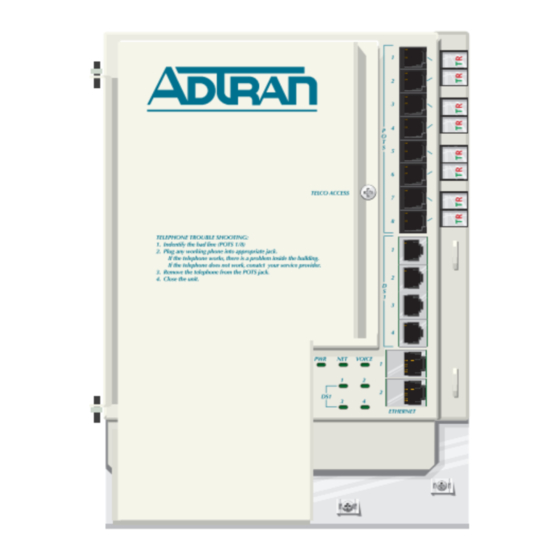
The Outer Enclosure base (refer to Figure 1) contains cable entry points for power, ground, Telco incoming cabling and cabling to the customer premesis. Each cable entry has grommets to provide environmental protection. The cable entries also support strain relief with Tie‐ wraps. Surface Mounting Telco Access Screw Hole TOTAL ACCESS 372 1287722G1 TELEPHONE TROUBLESHOOTING: 1. Identify the bad line (POTS 1-8). 2. Plug any working phone into the appropriate jack. If the telephone works, the unit is functioning normally. -
Page 20: Electronics Module
Total Access 372 Small Business Unit ONT Installation and Maintenance Guide Electronics Module The Electronics Module (see Figure 2) is not designed to be removed after the initial instal‐ lation. Figure 2. Electronics Module 61287722G1-5B... -
Page 21: Circuit Board
Components and Interfaces Circuit Board WARNING Do Not open the Electronics Module or attempt to remove the Circuit Board from the Electronics Module. The SBU ONT contains a single circuit board contained within the Electronics Module that provides the following functions: • Data Processing • Voice Processing • Alarm Reporting Data Processing The following data processing functions are performed: • Traffic management (priority queuing, scheduling, policing and traffic shaping) • Up to 16 VLANs • IGMP Snooping • QoS with four traffic classes per IEEE 802.1p • Full IEEE 802.1Q VLAN ID processing per port • 64 byte to 1600 byte packet sizes Voice Processing The POTS Voice Processing feature set is listed below: • Echo cancellation per ITU‐T G.168 ‐ up to 16 ms tails • Caller ID FSK tone generation • Fixed or adaptive jitter buffer •... -
Page 22: Alarm Reporting
Total Access 372 Small Business Unit ONT Installation and Maintenance Guide Alarm Reporting The circuit board provides alarm reporting for the Uninterruptible Power Supply (UPS). The following alarms are supported: • Low Battery • Battery Missing • Replace Battery • On Battery SBU ONT Interfaces The SBU ONT supports the following interfaces: • Eight (8) POTS • Four (4) DS1 • Two (2) 10/100/1000Base‐T Ethernet Connections • Power Ethernet Interface The SBU ONT supports data services through two 10/100/1000Base‐T Ethernet interfaces via RJ‐45 connectors. The Ethernet interface meets IEEE 802.3 specifications and is transformer coupled for 1500 V isolation. Both full and half duplex modes are supported. -
Page 23: Ups Power Supply
Components and Interfaces UPS Power Supply The power feed must be UL Listed ITE SPS having an Limited Power Supply (LPS) Output rated at 12 VDC, minimum 2 A, and suitable for the intended location. The SBU ONT utilizes an uninterruptible power supply (UPS). An UPS (see Figure 3) is a battery backup system designed to continue providing power when the primary power source is lost. When the UPS senses a loss of power from the primary source, the backup battery is activated to provide power for a short period of time. 85V AC- Power Converter 264V AC Battery Charger 12V DC Alarms Battery Alarms Backup Figure 3. Uninterruptible Power Supply (UPS) Power is supplied to the SBU ONT by an UPS local power source with battery backup that utilizes the AC power at the customer premises. The unit powers the SBU ONT and functions as a battery backup supplying continuous 12 VDC. It contains one sealed, lead‐acid battery for power backup. If the battery is disconnected, the SBU ONT is not protected from power outages, and will send a “Battery Missing” alarm to the OLT. Install the UPS per the specifications recommended by the manufacturer. 61287722G1-5B... -
Page 24: Installation
Total Access 372 Small Business Unit ONT Installation and Maintenance Guide Installation CAUTION C A U T I O N ! SUBJECT TO ELECTROSTATIC DAMAGE OR DECREASE IN RELIABILITY HANDLING PRECAUTIONS REQUIRED Electrostatic Discharge (ESD) can damage electronic components. When handling modules, wear an antistatic discharge wrist strap to prevent damage to electronic components. Place modules in antistatic packing material when transporting or storing. When working on modules, always place them on an approved antistatic mat that is electrically grounded. After unpacking the SBU ONT, inspect it for damage. Before planning the installation of the SBU ONT, the technician should do the following to verify component integrity. 1. Unpack both the SBU ONT and power supply (packed separately) to ensure the units are ... -
Page 25: Required Tools
Installation Required Tools Standard technician tools are used for a SBU ONT installation (for example, drill, drill bits, side cutters, screwdrivers, nut drivers, hex wrenches, wire strippers, etc.). Specifically, the following tools are required for the installation of the SBU ONT: • Carpenter’s level • 3/32” screw driver • 5/32” hex tamper‐proof bit • 216‐Type can wrench • Fiber splicing tools • Eight (8) RJ‐11 connectors for POTS testing (used in conjunction with each Pivot connection) • Two (2) RJ‐45 connectors for Ethernet connections • Four (4) RJ‐45 connectors for DS1 connections • A telephony/data communication test set • Power meter preferably with wave length filtering • Fiberscope or videoscope • Optical Time Domain Reflector meter calibrated for 1310 and 1490 nm output • Composite fiber cable for non‐connectorized installation • SBU ONT mounting hardware • Silicone sealant (and application material, i.e., cotton swabs) • Bonding clamp for grounding and securing the composite cable on non‐connectorized installations •... -
Page 26: Instructions For Installing The Sbu Ont
Total Access 372 Small Business Unit ONT Installation and Maintenance Guide Instructions for Installing the SBU ONT A typical exterior SBU ONT installation with UPS is shown in Figure 4. Customer provided premises wiring including CAT5 or higher Ethernet cable and POTS Communications twisted pairs to be Terminated Distribution in the ONT by technician... -
Page 27: Determining Sbu Ont Enclosure Location
Installation CAUTION • This equipment must be connected to a known, reliable earth ground at all times during installation and service. Refer to the National Electrical Code (NEC) and state/local codes for details on grounding requirements. A minimum 12 AWG copper ground conductor shall be used to connect the equipment to earth ground. • This equipment must be serviced by authorized service personnel only. All repair procedures are detailed to allow sub‐assembly level repairs ONLY. Authorized service personnel should not attempt component level repairs or circuit modifications to the printed circuit board. Improper repairs can create a safety hazard. Determining SBU ONT Enclosure Location General SBU ONT mounting requirements for both indoor and outdoor are as follows: • Maintain proper airflow in and around the unit at its final mounted location. Do not install siding and other building material around the outside of the enclosure to prevent excessive heat buildup and ultimate product failure. • Mount the unit within proximity of the AC electrical power meter where the Multi‐ Ground Neutral (MGN) is easily accessible. • Mount the unit away from down spouts, permanent water sprinklers, or other water sources. • Consider proper clearances for opening of the swinging SBU ONT covers. The height of the mounting can vary, however, it is recommended that the enclosure be installed at a vertical distance of approximately four feet (1.2 meters) from grade. This height lends to ease of installation/repair. Naturally, this mounting is dependent on the height of the customer provided inside wire and/or length or location of the buried fiber drop, which is assumed to enter the SBU ONT from the ground upwards. The enclosure is mounted vertically. If at all possible, the enclosure should be surface mounted on a flat surface. CAUTION Ensure the SBU ONT is grounded before making any other connections. 61287722G1-5B... -
Page 28: Mounting The Enclosure Outdoors
Total Access 372 Small Business Unit ONT Installation and Maintenance Guide Mounting the Enclosure Outdoors NOTE When installed outdoors, an Adtran Model 774 or 775 series NID housing must be used. Use a maximum of a #10 screw to fit properly in the diameter of the mounting holes (see Figure 5). Make sure to leave a minimum clearance of 2 inches (5.1 cm) from the hinges for opening the door. Complete the following steps to mount the enclosure: 1. Choose a vertical surface near an approved ground, but away from down spouts, perma‐ nent water sprinklers, or other water sources. 2. Use the top and bottom surface mounting holes and a carpenter’s level to mark the locations for the three mounting brackets on the mounting surface. 3. Pre‐drill the marked locations and install a minimum of 1/4 inch diameter lag bolts, with a minimum length of 3 inches that are appropriate to secure to wall studs. 4. Mount the SBU ONT to the subscriber premises. NOTE Consideration should be given to allow proper clearance for opening the ONT door. Surface Mounting Bracket Surface Mounting... -
Page 29: Install The Electronics Module
DS1 connections. To access these connections, loosen the Telco Access screw on the protective cover, the door opens to the left. Refer to Figure 6 when installing the Electronics Module in the Enclosure: 1. Align the slots on the reverse of the Electronics Module with the tabs on the Enclosure. 2. Slide the Electronics Module on to the tabs and align the Screw Slot with the threaded hole in the back plate. Slots on Reverse TOTAL ACCESS 372 1287722G1 TELEPHONE TROUBLESHOOTING: 1. Identify the bad line (POTS 1-8). 2. Plug any working phone into the appropriate jack. If the telephone works, the unit is functioning normally. -
Page 30: Installed Outdoor Sbu Ont
Total Access 372 Small Business Unit ONT Installation and Maintenance Guide Installed Outdoor SBU ONT Figure 7 displays the various wire routing and drops when the Electronics Module is completely configured and installed in the Enclosure. Note: Electronics Module Cover has been removed for illustration purposes. Note: The RJ-11 POTS ports are used for test purposes only. Electronics Tip (Green) -
Page 31: Ground Wire Connection
Installation Ground Wire Connection WARNING Take extreme care when attaching the ground connectors to the utility (earth) ground rod. If the ground is interrupted or disturbed in any way, an unsafe condition will exist. Refer to the National Electrical Code (NEC) and state/ local codes for details on grounding requirements. Complete the ground connection by completing the following steps: 1. Remove the rubber grommet from the housing (see Step 1 in Figure 8). 2. Insert a 12 AWG minimum solid copper ground wire through the rubber grommet (see Step 2 in Figure 8). 3. Remove 1/2” of the insulation jacket and install a UL Listed tin plated copper closed loop grounding type connector suitable for location of use (indoor or outdoor) having a hole size suitable for the # 6 ground stud (no larger than 6.3 mm). 4. Remove the nut on the threaded ground terminal. 5. Install the Ring Termination Stud on the ground terminal and tighten the nut as shown in Figure 9 on page 20. Use this example for all grommet and fiber/cable installations. Figure 8. Cable Ground Installation 61287722G1-5B... -
Page 32: Figure 9. Sbu Ont Ground Connection
Total Access 372 Small Business Unit ONT Installation and Maintenance Guide 6. Reinsert the rubber grommet with the ground wire back in the SBU ONT housing (see Step 3 in Figure 8 on page 19). 7. Ensure the ground wire is routed as shown in Figure 9. TOTAL ACCESS 372 1287722G1 TELEPHONE TROUBLESHOOTING: 1. Identify the bad line (POTS 1-8). 2. Plug any working phone into the appropriate jack. If the telephone works, the unit is functioning normally. -
Page 33: Alternative Grounding Method
• The secondary electrode must be spaced at least 8 feet (2.4 meters) from the primary electrode. • The 12 AWG ground wire should be connected to the ground rod with a UL Listed ground clamp. Local Power Source Wire Run WARNING • Before making any power connections to this equipment, verify the power is off (fuse removed/breaker tripped). • This equipment should only be operated from the type of certified/listed power supply recommended by the manufacturer. CAUTION • Use caution when routing wires and cables. Avoid severe bending and routing over sharp edges. Use grommet material when possible to avoid wear on cable insulation. • To reduce the risk of fire, use minimum no. 26 AWG telecommunications line cord. Installation of the Limited Power Source (LPS) will be dictated by on‐site conditions and local telephone company practices. Refer to Figure 10 on page 22 and the following steps to complete the installation. 1. Install the Local Power Source (LPS) wire run from the SBU ONT to the connector of the LPS via the customer provided PVC conduit (or method used by your local telephone company). For power, ADTRAN recommends using 16 AWG wire at a maximum of 100 feet (30.5 meters). For alarm signals, ADTRAN recommends using 24 AWG wire. Do not plug in the UPS green connector at this time. This will be done after the subscriber’s wire/ cables are terminated during turn‐up and testing. 2. If necessary, tie wrap both the 12 AWG ground wire and LPS wire run to the buried fiber drop cable riser conduit. 61287722G1-5B... -
Page 34: Sbu Ont Power Connector
Total Access 372 Small Business Unit ONT Installation and Maintenance Guide SBU ONT Power Connector The SBU ONT is provided with a 7‐pin Euro‐style connector (see Figure 10). Pin 1 Low Battery Battery Missing Pin 7 Replace Battery On Battery Signal Return 12V Return +12VDC Power/Alarm UPS Power Connector Connector Figure 10. Euro SBU ONT Power and UPS Connectors Table 4 lists the Pinout designations for the Power/Alarm Connector. -
Page 35: Figure 11. Power/Alarm Connector
Installation 4. Remove the rubber grommet from the housing and route the wires through the rubber grommet (see Figure 11). TOTAL ACCESS 372 1287722G1 TELEPHONE TROUBLESHOOTING: 1. Identify the bad line (POTS 1-8). 2. Plug any working phone into the appropriate jack. If the telephone works, the unit is functioning normally. If the telephone does not work, contact your service provider. -
Page 36: Installation Of The Power Supply
Total Access 372 Small Business Unit ONT Installation and Maintenance Guide Installation of the Power Supply WARNING • Before making any power connections to this equipment, verify the power is off (fuse removed/breaker tripped). • This equipment should only be operated from the type of certified/listed power supply supplied by the manufacturer with the equipment. NOTE When installing the UPS, refer to the UPS manufacture’s mounting instructions where possible. To install the uninterruptible power supply (UPS) complete the following steps: 1. Select a location for the UPS. When making this determination, consider the following: • This unit is not appropriate for outdoor placement. • Place the UPS in a safe area, free of excessive dust, and with adequate airflow. • Refer to UPS technical specifications table for details on temperature and humidity requirements. Do not operate outside these specified limits. 2. Use the template enclosed with the unit to mark the installation location. 3. Remove the battery cover from the UPS unit and remove the strap from the battery holding it to the shelf of the unit. 4. Disconnect the battery cable at the battery terminals if already connected to the battery. -
Page 37: Table 5. Ups Pin-Out Connection
Installation CAUTION Connecting the UPS incorrectly can cause damage to the unit. Use caution when connecting the wiring. Table 5. UPS Pin-Out Connection Pin-Out Pin-Out Description Power/Alarm LOW BAT BAT MIS REP BAT ON BAT SIG RTN 12 V RTN +12 VDC 9. Plug the UPS power cord into the utility power cord inlet on the UPS. 10. Plug the UPS power cord into the wall outlet. (The UPS battery charges when it is connected to the utility power. The battery charges fully during the first 18 hours of normal operation. Do not expect full battery run capability during this initial charge period.) 11. Verify indicator lights are in agreement with manufacturer specifications and the unit is functioning. 61287722G1-5B... -
Page 38: Subscriber Connections
Total Access 372 Small Business Unit ONT Installation and Maintenance Guide Subscriber Connections Refer to Figure 13 and Figure 14 on page 27 to install subscriber POTS, Ethernet and DS1 services. POTS Connections To connect POTS, refer to Figure 13 to complete the following steps: 1. Trim each wire to length. Identify each pair in the service cable. 2. Remove the rubber grommet from the housing and insert the POTS cables through the grommet. 3. Flip the pivot connector to the “up” position. 4. Insert the appropriate wires TIP (green) and RING (red). 5. Flip the pivot connectors to the “down” position. 6. Replace the rubber grommet in the housing. Pots TOTAL ACCESS 372... -
Page 39: Install Ethernet Connections
6. For Ethernet connections refer to Figure 14 and Table 6 to complete the following steps: 1. Route the Subscriber Ethernet wires through the same cable entry as the POTS cables. 2. Strip back the jacket of a CAT 5 or 6 cable and connect the 4 pair twisted wires to the RJ‐ 45 Plug using a RJ‐45 crimper. 3. Insert the terminated RJ‐45 jack into the appropriate ETHERNET 1–2 socket on the SBU ONT. TOTAL ACCESS 372 1287722G1 TELEPHONE TROUBLESHOOTING: 1. Identify the bad line (POTS 1-8). 2. Plug any working phone into the appropriate jack. If the telephone works, the unit is functioning normally. -
Page 40: Install Ds1 Connections
Total Access 372 Small Business Unit ONT Installation and Maintenance Guide Table 6. Ethernet Cable Pin-Outs (Continued) Ethernet RJ-45 Pin-out TRD1‐ Transmit/Receive Negative Green TRD3+ Transmit/Receive Positive White/Brown TRD3‐ Transmit/Receive Negative Brown Refer to Table 7 for Ethernet LED Indications. Table 7. Ethernet LEDs Label Indication Description Link Link is down or Administratively shut down Green 10/100/1000 link is up... -
Page 41: Install Fiber To The Unit
Installation Install Fiber to the Unit CAUTION Ensure that fiber used is UL Listed Optical Fiber Cable suitable for this application, and does not contain any metallic members or other electrical conductive materials. To install fiber to the SBU ONT, refer to Figure 15 and complete the following steps: 1. Route the fiber coming to the customer premesis through the rubber grommet as shown. 2. Trim the insulation on the fiber cable back so there is a sufficient length of fiber to attach the fiber connector to the end of the fiber cable. 3. Loosen the Cable Support Clamp and route the Strength Member through the Cable Support Clamp. Retighten the Cable Support Clamp. 4. Splice the Fiber to the Fiber Jumper Cable (Yellow) (P/N 31251291‐E). 5. Connect the Fiber Jumper Cable to the SC/APC connector at the bottom of the Electronics Module. 6. Replace Splice Tray cover. TOTAL ACCESS 373E 1287723G1 TELEPHONE TROUBLESHOOTING: 1. Identify the bad line (POTS 1-8). 2. Plug any working phone into the appropriate jack. -
Page 42: Mounting The Electronics Module Indoors
Total Access 372 Small Business Unit ONT Installation and Maintenance Guide Mounting the Electronics Module Indoors NOTE The Electronics Module must be installed in a Restricted Access location. To install the Electronics Module indoors, refer to Figure 16 and the following instructions: 1. Choose a vertical surface near an approved ground. 2. Attach a 3/4 inch mounting board (typically plywood) to the wall studs using four, 2.5 inch or greater wood screws. (This provides long‐term stability for the module.) 3. Use the two keyholes on the reverse of the Electronics Module as location marks and install two #6 Pan Head screws (1 inch or longer). Leave approximately 1/16 inch protruding from the mounting surface. 4. Slide the Electronics Module over the Pan Head screws and exert a small amount of downward pressure to ensure that the top of the slots are resting on the shafts of the screws. 5. Lock the Electronics Module in place with a #6 Pan Head screw through the slot on the bottom of the Electronics Module. 6. Attach the Grounding Wire to the Ground Lug and secure using the Ground Lug Nut. Do not over tighten. Plywood Support... -
Page 43: Installed Indoor Electronics Module
Installation Installed Indoor Electronics Module Figure 17 displays the various wire routing and drops when the Electronics Module is completely configured and installed. TOTAL ACCESS 373E 1287723G1 TELEPHONE TROUBLESHOOTING: 1. Identify the bad line (POTS 1-8). 2. Plug any working phone into the appropriate jack. If the telephone works, the unit is functioning normally. If the telephone does not work, contact your service provider. -
Page 44: Commissioning And Testing
Total Access 372 Small Business Unit ONT Installation and Maintenance Guide Commissioning and Testing This section provides detailed information on the following: • “Turn‐Up” • Depending on the local service provider’s requirements the technician may be required to perform additional tests beyond the SBU ONT on the Customer Provided Equipment (CPE) wiring and/or equipment. If this is the case, a power meter may be used to test the upstream and downstream signal types for voice, data, and video • “Secure the Unit” on page 33 • “Test for POTS Line Faults” on page 34 • “Provision Ethernet Interface at OLT” on page 34 Turn-Up Initial turn‐up of the SBU ONT involves applying power and observing LEDs for status infor‐ mation. To complete the turn‐up of the SBU ONT, complete the following steps: 1. Plug the green UPS connector into the male connector of the UPS. 2. Check to ensure the AC, output, and battery LEDs are green and functioning. The UPS is now ready for normal operation. 3. View the LEDs on the SBU ONT as they cycle through start‐up diagnostics. A properly ... -
Page 45: Front Panel Leds
Commissioning and Testing Front Panel LEDs The SBU ONT provides front panel LEDs to display status information. The SBU ONT LEDs and status descriptions are shown in Table 9. Table 9. Front Panel LEDs Label Status Description No power Green Power is On Green OLT has activated the ONT Yellow OLT is discovering and ranging the ONT The OLT has shut down ONT VOICE Idle or Administratively Shut Down Green At least one port is Off Hook Green Flashing At least one port is Ringing Shut Down or no fiber to download original configuration 1 - 4 Green Link is us Yellow Test pattern or Loopback DS1 has alarm or configuration issue ETHERNET Link is down, no activity, or Administratively Shut Down 1 and 2 Green... -
Page 46: Test For Pots Line Faults
Total Access 372 Small Business Unit ONT Installation and Maintenance Guide Test for POTS Line Faults Look at the “TELEPHONE TROUBLESHOOTING” instructions on the front of the Electronics Module for directions in determining line faults. NOTE If the problem is still not corrected, it is possible there is an internal wiring problem with the premises. Provision Ethernet Interface at OLT Ensure Provisioning of the SBU ONT at the OLT has been completed. For the provisioned Ethernet link, use external equipment (for example, a laptop computer) to verify the Ethernet link is active. 61287722G1-5B... -
Page 47: Troubleshooting
Troubleshooting Troubleshooting When troubleshooting a SBU ONT unit, consider the following two principles: • Because voice and data signals originate at the OLT equipment, a failure of all services normally indicates the problem is before the SBU ONT. A failure at the OLT equipment normally results in a loss of service to multiple customers. • The OLT has diagnostic testing procedures that can monitor the status of every SBU ONT in the system, which very often can direct you to the root cause of the trouble. NOTE The home telephone wires are connected using pivot connectors, and the RJ‐ 11 jack serves as a test access point. In this configuration, inserting a telephone cable into the RJ‐11 jack will disconnect the SBU ONT from home wiring and connect the SBU ONT to the inserted cable instead. This allows the home owner or service provider to diagnose SBU ONT or home wiring related problems. Inserting an RJ‐11 jack (such as a telephone cable or telephone test set) into the connector, will connect the telephone set and also disconnect the subscriber service from the SBU ONT. Hence fault may be isolated to the SBU ONT or premises wiring. This section describes how to troubleshoot and correct the following: • “Faults Indicated with LEDs” • “SBU ONT Trouble Isolation” on page 36 • “Signal Level Verification” on page 39 • “UPS Communication Signals” on page 41 Faults Indicated with LEDs Begin troubleshooting at the SBU ONT by checking to see if all LEDs are in their normal state, shown in Table 9 on page 33. There are separate LEDs for each Ethernet RJ‐45 jack that appear on the SBU circuit board. If the LEDs are in their normal state, refer to “LEDs in Normal State” ... -
Page 48: Leds In Fault State
Total Access 372 Small Business Unit ONT Installation and Maintenance Guide LEDs in Fault State Descriptions of each LED are listed in Table 9 on page 33 with possible causes for fault LED conditions. A flow chart for troubleshooting the problem for each fault condition is provided in Figure 18 on page 37. SBU ONT Trouble Isolation This section describes how to isolate problems based on faults reported through LEDs: • “UPS Power LEDs” • “NET Status LED Off” on page 37 • “POTS Troubleshooting” on page 38 UPS Power LEDs Power A UPS LED that is off indicates there is no power. Refer to Table 10 to determine if a problem exists. -
Page 49: Net Status Led Off
Troubleshooting NET Status LED Off The LED Off indicates no signal detected, or the SBU ONT has been administratively shut down. This can be caused by one of the following conditions: • Failure at the OLT • Failure between the OLT and the SBU ONT before the drop wire optical connector • Drop wire optical connector • Malfunction of LED at SBU ONT Utilize the flowchart in Figure 18 to determine the cause and correct the problem. NET LED RED Check reflective Is there Work with power with Optical a failure at OLT admin power meter the OLT? to resolve Is power Replace ONT NET LED solid green... -
Page 50: Pots Troubleshooting
Total Access 372 Small Business Unit ONT Installation and Maintenance Guide POTS Troubleshooting When the POTS LED is red, the port is in a fault condition. To correct the problem, do the following: • Contact the OLT administrator and ensure the port is provisioned and working. If the port is provisioned and working, proceed to the next step. • Disconnect the CPE wiring and wait 30 seconds. If the Red LED turns off, the trouble is a short in the housing wiring. If the RED LED remains on, the unit is probably bad. Cleaning and Inspection of Components Because the physical size of the transmission core of the optical fiber is typically only 9 microns in size, debris such as a single particle of dust or smoke or strand of hair can impair the path enough to cause transmission problems. This section provides information and procedures for the following: • “Cleaning Suggestions” • “Cleaning the Connectors” • “Signal Level Verification” on page 39 Cleaning Suggestions Following is a list of suggestions for cleaning connectors, ferrules, and bulkheads: •... -
Page 51: Signal Level Verification
Troubleshooting Signal Level Verification The following sections detail signal level verification if problems are encountered when service activation of an installed SBU ONT is performed. Both Downstream signal Level Verification on page 40 and “Upstream Signal Level Verification” on page 40 are discussed. Downstream Signal Level Verification A valid optical power level delivered by the OLT must be received at the drop cable point to assure proper SBU ONT ranging and operation. There is one optical wavelength (1490 nm) to consider in the downstream direction that will contribute to the absolute optical power level delivered to the SBU ONT. The 1490 nm wavelength is used for digital data. The individual optical power level that should be present at the optical fiber that is connected to the SBU ONT are listed in Table 11. Table 11. Downstream Power Level Optical Wavelength Minimum Power Level 1490 nm (digital) –28 dBm To verify the correct downstream optical signal levels are present: Ensure all connectors are clean and dry. Refer to “Cleaning and Inspection of Compo‐ nents” on page 38 for details. 2. Setup and calibrate the OPM or OLTS for wavelengths that apply to FTT transmissions (that is 1310 nm and 1490). Verify the test equipment is capable and setup for wavelength filtering so that you do not obtain an undesired reading of the absolute optical power from all contributing wavelengths. Instead you are trying to measure the individual wavelength optical power levels. -
Page 52: Upstream Signal Level Verification
Total Access 372 Small Business Unit ONT Installation and Maintenance Guide • If the measurement results are within range, perform the steps in “Upstream Signal Level Verification” on page 40. Upstream Signal Level Verification A valid optical power level delivered by the SBU ONT must be received by the OLT in burst mode at 1310 nm that is controlled in the upstream direction by grants given by the OLT. The individual optical power level that should be present at the optical bulkhead that is located on the SBU ONT is listed in Table 12. Table 12. Upstream Power Levels Optical Wavelength Minimum Power Level Maximum Power Level 1310 nm 0 dBm +5 dBm To verify the correct upstream optical signal level is present: Ensure all connectors are clean and dry. Refer to the “Cleaning and Inspection of Compo‐... -
Page 53: Ups Communication Signals
Troubleshooting UPS Communication Signals The communication signals of the UPS are isolated from the internal circuitry via open SIG RTN collector opto‐coupled transistors. The connection (Signal Return) is a common return point for all communication signals. In the typical application, the attached equipment digital ground connects to Signal Return, and pull‐up resistors turn the open collector signals into logic levels. A pinout of the communication signals is shown in Table 13. Table 13. UPS Communication Signal Descriptions Signal Description +12 VDC Vo+ (+ Voltage output) 12 V RTN Return path for +12 VDC SIGNAL RETURN Signal return ON BATTERY Low when operating from utility line Open when operating from battery REPLACE BATTERY Low when battery is charged Open when battery fails self‐test BATTERY MISSING Low when battery is present Open when battery is missing LOW BATTERY Low when battery is near full charge capacity Open when operating from a battery with less than 20% capacity 61287722G1-5B... -
Page 54: Maintenance
Total Access 372 Small Business Unit ONT Installation and Maintenance Guide Maintenance The SBU ONT does not require routine maintenance for normal operation. Do not attempt to repair the SBU ONT in the field. Repair services are obtained by returning the defective unit to ADTRAN. Refer to “Appendix A, Warranty and Customer Support” for further information. Specifications Specifications for the SBU ONT are detailed in Table 14. Table 14. Specifications Specification Description Power Voltage Range: 12 VDC (nominal), 10.8 VDC to 14.4 VDC (tolerance) Maximum Current: 2.0 Amp Environmental Operating Temperature: –40°C to +65°C (–40°F to 149°F) Outdoors –40°C to +50°C (–40°F to 149°F) Indoors Storage Temperature: –40°C to +85°C (–40°F to 185°F) Relative Humidity: 0 to 95% noncondensing within enclosure Physical Dimensions: Height: 15 inches (38.1 cm) Width: 9.75 inches (24.8 cm) Depth: 4 inches (10.1 cm) Weight: 15 pounds (6.8 kg) -
Page 55: Warranty
Appendix A Warranty and Customer Support Warranty ADTRAN will replace or repair our products within the warranty period if they do not meet their published specifications or fail while in service. Warranty information can be found at www.adtran.com/warranty. ADTRAN Customer Care From within the U.S.: 1.800.726.8663 From outside the U.S.: +1 256.963.8716 ADTRAN Sales Pricing/Availability: 1.800.827.0807 ADTRAN Technical Support ADTRAN offers Technical Support Engineering services for all of our products. These services are provided at no charge during the product warranty period. Pre‐Sales Applications/Post‐Sales Technical Assistance: 1.800.726.8663 Standard hours: Monday ‐ Friday, 7 a.m. ‐ 7 p.m. CST Emergency hours: 7 days/week, 24 hours/day Email: support@adtran.com Web: http://www.adtran.com/getsupport ADTRAN Repair/CAPS Return for Repair/Upgrade: 1.256.963.8722 Repair and Return Address Contact CAPS prior to returning equipment to ADTRAN. ADTRAN, Inc. CAPS Department 901 Explorer Boulevard Huntsville, Alabama 35806‐2807... - Page 56 Carrier Networks Division 901 Explorer Blvd. Huntsville, AL 35806 U.S.A. http://www.adtran.com ADTRAN CUSTOMER CARE From within the U.S. 1.800.726.8663 From outside the U.S. +1 256.963.8716 PRICING AND AVAILABILITY 1.800.827.0807...
Need help?
Do you have a question about the Total Access 372 and is the answer not in the manual?
Questions and answers