Table of Contents
Advertisement
Quick Links
Advertisement
Table of Contents

Related Manuals for Cecilware GB4M-5.5-LD-U


Summary of Contents for Cecilware GB4M-5.5-LD-U
- Page 1 GB4M-5.5-LD-U GB5-LD-U GB6M-10-LD-U GB8M-10-LD-U Operation Manual NL48A July 2005...
-
Page 2: Table Of Contents
CONTENTS Important Owner Information_____________________________________1 Introduction____________________________________________________1 Important Safety Instructions___________________________________2 Model Description_______________________________________________3 Specifications__________________________________________________3 Plug Configurations_____________________________________________3 Installation____________________________________________________4 Start-up Procedure______________________________________________5 Troubleshooting Guide___________________________________________6 Recommended Cleaning and Sanitizing_____________________________7 Dual Probe Liquid Level Controller______________________________8 Components Tests________________________________________________9 Hopper Assembly________________________________________________10 Whipper Chambers_______________________________________________11 Body Frame_____________________________________________________12 Electrical Chassis_____________________________________________21 Upper Door_____________________________________________________22 Lower Door_____________________________________________________23 Hot Water Tanks________________________________________________24 Electrical diagram_____________________________________________26... -
Page 3: Important Owner Information
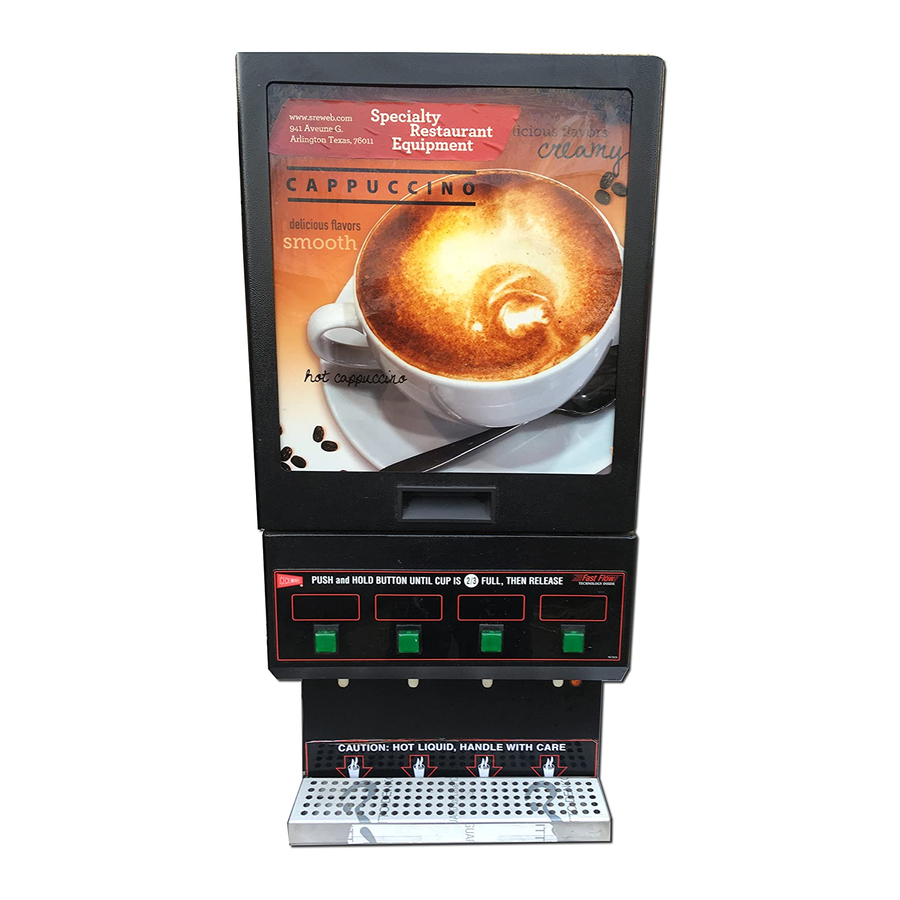
Additional information can be found by visiting our web site at www.cecilware.com INTRODUCTION The Cecilware 5, 6, & 8 head instant Cappuccino Dispenser is designed to meet the exact needs of the Convenience Store atmosphere. Cecilware has led the way in the highly profitable and growing market of Cappuccino with its GB series of Automatic Cappuccino Dispensers. -
Page 4: Important Safety Instructions
Some aftermarket or generic replacement parts do not have the characteristics that will allow them to operate safely in Cecilware equipment. It is essential to use Cecilware Replacement Parts when repairing Cecilware equipment. Failure to use Cecilware Replacement Parts may subject operators of the equipment to hazardous electrical voltage, resulting in electrical shock or burn. -
Page 5: Model Description
Only Cecilware brings you this type of versatility. With its top hinged and bottom hinged door design, its 27 inch footprint (left to right) allows maximum utilization of counter space. -
Page 6: Installation
GB8M-10-LD-U: There are two (2) Water Connections. (2) ¼ inch Flare Water Inlet Fittings are located on the left and right side in the back of unit. GB4M-5.5-LD-U, GB5-LD-U, & GB6M-10-LD-U: There is one (1) Water Connection, (1) ¼ inch Flare Water Inlet Fitting located on the back of unit. -
Page 7: Start-Up Procedure
START-UP PROCEDURE Caution: Make sure that the Heater Switches, are in the OFF position. 1. Connect the ¼ inch copper waterlines to the ¼ inch flare water inlet fittings of the valves. 2. Plug the power cords into dedicated receptacles. 3. -
Page 8: Troubleshooting Guide
WARNING : To reduce the risk of electrical shock, or replacing any internal components of the unit. Before any attempt to replace a component be sure to check all electrical connections for proper connection. PROBLEM PROBABLE CAUSE Dispensing unit unplugged. Light display No power from Terminal Block. -
Page 9: Recommended Cleaning And Sanitizing
Model L690A (Rev. B) Dual Probe Liquid Level Controller Overview - The L690A is a Dual Probe Liquid Level Controller designed to maintain a specific level of water in the tank. This device utilizes two level probes for increased reliability. Independent maximum fill timers are incorporated in the controller for overflow protection. -
Page 12: Hopper Assembly
WHIPPER CHAMBER IMPORTANT: SLANTED WHIPPER CHAMBERS (SEE BELOW) ARE NOT INTERCHANGEABLE WITH STANDARD STRAIGHT WHIPPER CHAMBERS. BE SURE TO ORDER USING THE CORRECT PART NUMBERS. ITEM IMPELLER (1 FLAT) USE W/ CD75A) IMPELLER (2 FLATS) USE W/ CD75A OR CD350 SLANTED WHIPPER CHAMBER... - Page 13 HOPPER COVER AGITATOR WHEEL W/SPRINGS AUGER MOTOR #CD175 (90 RPM) AUGER BUSHING FRONT CD306 NUT CD278 [2] BEVELLED SOCKET CD271 PRODUCT GUIDE, SHORT AUGER BUSHING-BACK CD279 CD70A HOPPER BASE CD140...
-
Page 14: Body Frame
HOPPER COVER AGITATOR WHEEL W/SPRINGS AUGER MOTOR #CD175 (90 RPM) AUGER BUSHING FRONT CD306 NUT CD278 [2] BEVELLED SOCKET CD271 PRODUCT GUIDE, SHORT AUGER BUSHING-BACK CD279 CD70A HOPPER BASE CD140... - Page 15 HOPPER COVER AGITATOR WHEEL W/SPRINGS AUGER MOTOR #CD175 (90 RPM) AUGER BUSHING FRONT CD306 NUT CD278 [2] BEVELLED SOCKET CD271 PRODUCT GUIDE, SHORT AUGER BUSHING-BACK CD279 CD70A HOPPER BASE CD140...
-
Page 23: Electrical Chassis
TANK DIMENSIONS: 12" WIDE, 4.8" DEEP, 16.5" HIGH. APPROX. 3.7 GAL. ITEM DESCRIPTION... -
Page 24: Upper Door
TANK DIMENSIONS: 15" WIDE, 6" DEEP, 18" HIGH. APPROX. 6 GAL. ITEM DESCRIPTION... -
Page 26: Hot Water Tanks
BREW BREW SWITCH SWITCH DOOR UNIT MAIN UNIT RINSE SWITCH AUGER CONTACTOR RELAY WATER INLET TANK HEATER 1.7KW 5-15R GB5-LD-U 15A-1.7KW BREW SWITCH DISPENSE DISPENSE VALVE VALVE AUGER WHIPPER WHIPPER RELAY RELAY VALVE LIQUID LEVEL CONTROL WATER LEVEL PROBES WATER HI-LIMIT THERMOSTAT 5-15P... - Page 27 GB6M-10-LD-U...
-
Page 28: Electrical Diagram
WATER LEVEL PROBES WATER GB8M-10-LD-U & GB8M10WLD ELECTRICAL DIAGRAM - LEFT SIDE - 120V DISPLAY LIGHTS LIQUID LEVEL CONTROL REV A NE195 SHEET 1 OF 2... - Page 29 WATER LEVEL PROBES WATER GB8M-10-LD-U & GB8M10WLD ELECTRICAL DIAGRAM - RIGHT SIDE - 120V DISPLAY LIGHT LIQUID LEVEL CONTROL REV A NE195 SHEET 2 OF 2...
Need help?
Do you have a question about the GB4M-5.5-LD-U and is the answer not in the manual?
Questions and answers