Advertisement
Quick Links
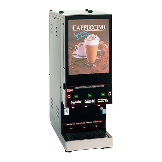
CAPPUCCINO, COFFEE, and SOUP DISPENSERS
Cecilware sells value... Worldwide
45 -05 20th Avenue, Long Island City, NY 11105
GB models:
•SUPER HIGH CAPACITY
•SPACE SAVER
•FEATURE FLAVOR
•STAINLESS STEEL [S/S]
•BUDGET [K]
•SKI
•OCS
•LOW PROFILE [LP]
OPERATION MANUAL
• Specifications................................................. 2
• Installation and Operating Instructions........ 3
• Adjustments................................................... 6
• Trouble Shooting Guide................................ 10
• Care and Maintenance..................................11
• Parts Identification....................................... 17
• Wiring Diagrams........................................... 20
•
718-932-1414
FAX
718-932-7860
NA33A-C 3/1/2003
Advertisement

Related Manuals for Cecilware GB4M5.5


Summary of Contents for Cecilware GB4M5.5
- Page 1 • Installation and Operating Instructions..3 • Adjustments........... 6 • Trouble Shooting Guide......… 10 • Care and Maintenance........11 • Parts Identification........17 • Wiring Diagrams........... 20 Cecilware sells value... Worldwide • 45 -05 20th Avenue, Long Island City, NY 11105 718-932-1414 718-932-7860 NA33A-C 3/1/2003...
- Page 2 Models and Mechanical Specifications MODEL: WIDTH DEPTH HEIGHT HOPPERS TANK BURST LIT DISPLAY AREA SHIPPING QTY . GAL. HOT CAPACITY (W x H) Sq. in. WEIGHTLB. WATER GB2-LD DELUXE-SUPER HIGH CAPACITY (7 x 13) 91 GB3-LD 1+ 2 5 ½ & 10 2.75 (9½...
- Page 3 Electrical Specifications Number of Receptacle Circuit Model No. Volts Phase Watts Heaters Amps Nema No. Breaker ALL MODELS 120V 1.8KW 5-15R GB3K [NES] 120V 1.8KW 5-15R ALL MODELS 120/240V 3.0KW L14-20R** ALL EXPORT MODELS 220V 3.0KW †† GB3\4 120/240V 6.0KW L14-30R** GB8M 120 EACH...
-
Page 4: Unpacking Instructions
Carefully unpack the GB Machine and inspect immediately for shipping damage. Your GB Machine was shipped in a carton designed to give it maximum protection in normal handling. It was thoroughly inspected before leaving the factory. In case of damage, contact the shipper, not Cecilware. DESCRIPTION AND LOCATION OF COMPONENTS Note: Refer to Illustration A for description and location of COMPONENTS and CONTROLS. - Page 5 GB2SKI - 14 lb GB2M5.5 - 5.5 lb. FRONT VIEW FRONT VIEW w/ OPEN DOOR GB2M - 4 lb. w/OPEN DOOR FRONT VIEW OCS2 - 4 lb. GB2LP - 4 lb. (14 1/8"W x 23 1/4"D x 38"H) w/OPEN DOOR (8.5"W x 22"D x 31.5"H) FRONT VIEW FRONT VIEW...
- Page 6 The Dispense Valves are factory adjusted for a maximum Flow Rate of 1 to 1.3 oz./sec . Approximate settings: 0.85 to 1 oz./sec for SOUP ; 1.3 oz./sec. for COFFEE and CAPPUCCINO ] Exceeding this Flow Rate will cause the Mixing Chamber to overflow. Note: To access the Water Dispense Valves, open door and remove Hoppers.
-
Page 7: Thermostat Adjustments
THERMOSTAT ADJUSTMENTS Locate Thermostat: Remove the right side panel. Thermostat is mounted on side of tank. (L029A) THERMOSTAT 120/240V, 3 KW & 6 KW The GB beverage dispensers are factory set to deliver hot brewing water at 195°F USED ON GBs with the thermostat knob turned to full ON position. - Page 8 EDDRINK STRENGTH ADJUSTMENTS - by adjusting the Auger Speed. I. UNITS WITH FIXED SPEED AUGER MOTORS-AC [CD150] - Fixed Auger Speed [95 RPM] and dispenses powder at a constant fixed rate. Drink Strength adjustments can be made by adjusting the water flow rate on the Water Dispense Valves . [See ILL. C] 1.
- Page 9 A) Water Inlet Valve Test Turn power off. If the water level rises inside the tank, the Water Inlet Valve is leaking. Disconnect wires from the Water Inlet Valve coil and connect a 2 wire line cord to the terminals. Plug it into a 115V outlet. If water flows in and stops when CHECK VALVE ASSY L463A you pull it out, the Valve is working fine.
-
Page 10: Troubleshooting Guide
TROUBLESHOOTING GUIDE WARNING: To reduce the risk of electrical shock unplug the dispenser power cord before repairing or replacing any internal components of the unit.. Before any attempt to replace a component be sure to check all electrical connections for proper contact. PROBLEM PROBABLE CAUSE REMEDY... - Page 11 SANITIZING: All sanitizing agents in the food zone must comply with 21 CFR 178.1010. All food dispensing units should be sanitized periodically. All parts to be sanitized must be cleaned first. To prepare a sanitizing solution: ADD 2 TSP. OF LIQUID CLOROX BLEACH (5.25% CONCENTRATION) TO 1 GALLON OF WATER AT ROOM TEMPERATURE (70°- 90°F).
- Page 12 LIT DISPLAY AND STARTER REPLACEMENT ILL. E To replace the fluorescent bulb: BULB TYPE F8T5/CW STARTER TYPE Remove the upper inside door FS-5 panel. Turn the lamp and pull it LAMP HOLDER out of the lamp holder, then PRODUCT LABEL place the new lamp into the CORD SET CORD SET...
- Page 13 HOPPER ASS'Y CD104, 7 LB, 18"HIGHT x 3"W, W/NYLON AUGER HOPPER ASS'Y CD105 (14 lb; 18"H IGHT X 6.25"SQ) W/NYLON AUGER HOPPER ASS'Y CD120, 5.5 LB, 14"HIGHT x 3"W, W/NYLON AUGER HOPPER ASS'Y CD99A (8 lb; 11.5"]HIGHT X 6.25"SQ) W/NYLON AUGER HOPPER ASS'Y CD68A, 4 LB, 11.5"HIGHT x 3"W, W/NYLON AUGER HOPPER ASS'Y CD313, 1 LB COFFEE, 7.875"...
- Page 14 HOPPER ASS'Y CD144, 5.5 LB, 14"Hx 3"W, W/WIRE AUGER CD101 HOPPER ASS'Y CD163 (14 lb; 18"H IGHT X 6.25"SQ) W/WIRE AUGER HOPPER ASS'Y CD152, 4 LB, 11.5"H x 3"W, W/WIRE AUGER CD101 HOPPER ASS'Y CD162 (11 lb; 14"HIGHT X 6.25"SQ) W/WIRE AUGER HOPPER ASS'Y CD98A, 4 LB, 11.5"H x 3"W, W/WIRE AUGER CD74A or CD153 HOPPER ASS'Y CD161 (8 lb;...
- Page 15 1. SCREW, S.S., 1/4 - 20 x 5/8 P465A 2. SHIM ASSEMBLY, HEAT SINK W/HI-LIMIT BRACKET K667Q 3. HEATER, 120V 1700W G267A HEATER, 240 V, 3000W G266A 4. O-RING, HEATER GASKET M773A 5. HI-LIMIT, #500, 200°F CUTOUT L656A 6. HEATSINK, 1/8" ALU. F/ HI-LIMIT K661A 7.
- Page 16 ILL. J...
-
Page 17: Parts Identification List
PARTS IDENTIFICATION LIST (* See METAL PARTS LIST for ITEMS 4, 23, 24, 45, 53 [next page]) GBM 5.5 GB-LP DESCRIPTION ITEM GBM 5.5 GBK 5.5 GB SKI SILICONE HOSE [WATER INLET VALVE-—TANK] [ .375 I.D. x 13” ] M484A M484A M484A M484A... - Page 18 METAL PARTS IDENTIFICATION LIST ITEM 4 ITEM 23 ITEM 24 ITEM 45 ITEM 53 MODEL TANK | TANK TOP DRIP TRAY DRIP TRAY DOOR SIDE ASS’Y | ASS’Y GRILL WELDMENT PANELS [1 HEATER 1.8KW or 3KW] ASSY GB1M SPACE SAVER SC35C SC32C RI23A...
- Page 19 HOT/COLD WATER VALVE CONVERSION KIT INSTALLATION INSTRUCTIONS: SWITCH LABEL NB10A 1. REMOVE EXISTING BOTTOM BACK PANEL. 2. INSTALL KIT/PANEL WITH THE 4 SCREWS SUPPLIED. HOT/COLD SWITCH 3. CONNECT HOSE (FROM TANK) WATER INLET, TO DUAL VALVE AS SHOWN. L497A BEHIND HOPPER 4.
- Page 40 CECILWARE CORPORATION...
- Page 41 CECILWARE CORPORATION...
- Page 42 CECILWARE CORPORATION...
- Page 43 CECILWARE CORPORATION...
Need help?
Do you have a question about the GB4M5.5 and is the answer not in the manual?
Questions and answers