Advertisement
Quick Links
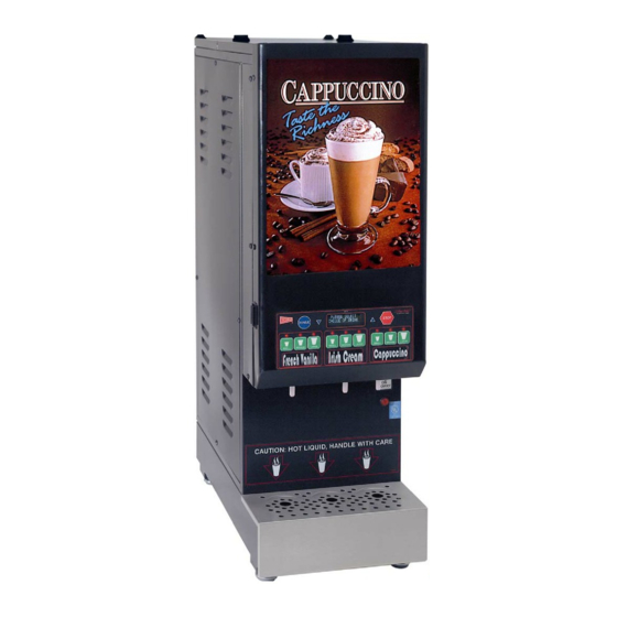
CAPPUCCINO, COFFEE, and SOUP DISPENSERS
Cecilware sells value... Worldwide
45 -05 20th Avenue, Long Island City, NY 11105
•
TEL
718-932-1414
•
FAX
718-932-7860
GB-IT (Intelligent Technology)
• Microprocessor Technology
• Touch Pad Control Panel
• Free Flow and Portion Control
• Counts Total Number of Cups Dispensed
• Automatic Rinse Cycle
• Diagnostics for Electrical Problems
• Removable & Replaceable Picture
easy – no assembly required
OPERATION MANUAL
• Specifications...................................................... 2
• Installation and Operating Instructions.............. 4
• Adjustments......................................................... 6
• Programming Instructions................................. 8
• Care and Maintenance........................................ 8
• Trouble Shooting Guide..................................... 11
• Parts Identification............................................. 15
• Wiring Diagrams................................................ 21
NG95A-A 11/10/04
Advertisement

Related Manuals for Cecilware GB-IT


Summary of Contents for Cecilware GB-IT
- Page 1 CAPPUCCINO, COFFEE, and SOUP DISPENSERS Cecilware sells value... Worldwide 45 -05 20th Avenue, Long Island City, NY 11105 • 718-932-1414 • 718-932-7860 GB-IT (Intelligent Technology) • Microprocessor Technology • Touch Pad Control Panel • Free Flow and Portion Control • Counts Total Number of Cups Dispensed •...
- Page 2 Carefully unpack the GB Machine and inspect immediately for shipping damage. Your GB Machine was shipped in a carton designed to give it maximum protection in normal handling. It was thoroughly inspected before leaving the factory. In case of damage, contact the shipper, not Cecilware. INSTALLATION INSTRUCTIONS Water Inlet Connection: This equipment is to be installed to comply with the applicable Federal, State, or local plumbing codes having jurisdiction.
- Page 3 The door display panel will light up and the tank will start filling. The LCD window will display this message briefly “CECILWARE, DISPENSER V#.## “. 4. The LCD window will display this message “Low Water Level”. Allow approximately 3-5 minutes for the tank to fill.
- Page 4 GB3M-5.5-IT DIMENSIONS & CONPONENTS LOCATION - ILL. A FRONT VIEW HOPPER LABEL AREA DISPENSE BUTTON (9) PRODUCT LABEL LATCH PRODUCT GUIDE DISPENSE CHAMBER MIXING CHAMBER PLEASE SELECT DRINK ... TECHNOLOGY INSIDE WHIPPER CHAMBER DISPENSE NOZZLE NA88A DRIP TRAY RIGHT SIDE VIEW DISPENSE VALVE TOUCH PAD LCD BOARD...
- Page 5 ADJUSTMENTS - ILL. B WATER FLOW RATE The Dispense Valves are factory adjusted fo r a maximum Flow Rate of 1 to 1.3 oz./sec. [Approximate settings: 0.85 to 1 oz./sec for SOUP; 1.3 oz./sec. for COFFEE and CAPPUCCINO] Exceeding this Flow Rate will cause the Mixing Chamber to overflow. Note: To access the Water Dispense Valves, open door and remove Hoppers.
- Page 6 Features and Benefits of the Digital Dispenser Controller 1. 100% Solid State Control for improved reliability 2. Modular design and reduced component count for ease of service 3. Optional sanitary features such as Rinse Lockouts and Rinse Warnings 4. Redundant system interlocks for uncompromising user safety 5.
- Page 7 PARAMETER DEFINITIONS FOR SYSTEM SOFTWARE VERSION 1.11 Grand Total – This parameter indicates the total amount of water dispensed (in ounces or milliliters) for the entire machine. The Grand Total does not include Rinse Dispenses. The maximum Grand Total value is 16,777,216 ounces; after which the value will begin again from zero.
- Page 8 13. Rinse Warning Status – This parameter determines whether the Rinse Warning Option is turned ON or OFF. If this option is ON the system generates a Rinse Warning if a Hopper has dispensed and has not been Rinsed for of time greater than that defined by (50 * Rinse Lockout Time) minutes.
- Page 9 Normal Mode. The main function of this mode is to provide limited access to frequently used system parameters. 5. Service Mode – This mode becomes active when the hidden keys under the “Cecilware Logo” and the “Fast Flow Logo” are simultaneously depressed for more than 1.5 seconds while in Normal Mode.
- Page 10 PROGRAM MODE General Conventions (unless otherwise indicated) 1. To enter or exit Program Mode simultaneously depress both the Rinse key and the Stop key until the buzzer sounds (approximately 1.5 seconds). 2. Pressing the Stop key will cause the menu to scroll up and pressing the Rinse key will cause the menu to scroll down. 3.
- Page 11 SERVICE MODE General Conventions: 1. To enter or exit Service Mode simultaneously depress both the hidden key behind the Cecilware Logo and the hidden key behind the Fast Flow Logo until the buzzer sounds (approximately 1.5 seconds). 2. Pressing the Stop key will cause the menu to scroll up and pressing the Rinse key will cause the menu to scroll down.
- Page 12 If the Stop key is pressed the LCD/VFD screen will display the following: Pressing any of the Dispense keys will cause the Dispense LED(s) of the corresponding Hopper to blink and the LCD/VFD screen will display the Gram Throw for the indicated Hopper as follows: If the Stop key is pressed the LCD/VFD screen will display the following: Pressing any of the Dispense keys will cause the Dispense LED(s) of the corresponding...
- Page 13 If the Stop key is pressed the LCD/VFD screen will display the following: If the Stop key is pressed the LCD/VFD screen will display the following: If the Stop key is pressed the LCD/VFD screen will display the following: If the ▼and ▲ keys are pressed Low Temperature Lockout will toggle between “on” and “off”. If the Stop key is pressed the LCD/VFD screen will display the following: If the Stop key is pressed the LCD/VFD screen will display the following: Pressing any of the Dispense keys will cause the Dispense LED(s) of the corresponding...
- Page 14 DEFINITION OF SCREENS DURING NORMAL OPERATION: Initialization Screen Definition – This screen is displayed only during the first few seconds after “power-on”. The only purpose of this screen is to display the System Software Title (DISPENSER) and Version Number (V #.##). Low Water Level Screen Definition –...
- Page 15 DEFINITION OF ERROR SCREENS AND TROUBLESHOOTING IF ANY OF THESE ERROR SCREENS COME UP ALSO CHECK THE SAFETY RELAY IN ADDITION TO THE COMPONENT IN QUESTION. SEE RELAY TEST. 1. Over Temperature Error Screen Definition – This screen is displayed and the system is shut down when the present water temperature is sensed higher than 208 °F.
- Page 16 Note: IF either the Auger Motor, or Mixer Motor, or Solenoid Error Screen appear: The entire system is inoperable this means that one of either the Auger Motor, or Mixer Motor, or Solenoid [Dispense Valve] is not functional while that Hopper Status in ON. To continue operating the other Hoppers: Go into Program Mode [by pressing simultaneously the Rinse and Stop keys], Press RINSE to get the HOPPER STATUS screen, Press ▼or ▲key to set the non-functional HOPPER STATUS to OFF;...
- Page 17 RECOMMENDED PREVENTIVE MAINTENANCE 1. CHECK ALL DISPENSE VALVES FOR LIME BUILD-UP. •Drain The Water Tank To Just Below The Level Of The Dispense Valves. •Remove The Valves And Clean. ( You Can Take These Valves Apart By Hand As Shown). •Replace The Assembly As Needed (L467A).
- Page 18 PICTURE / DURATRAN REPLACEMENT and BULB AND STARTER REPLACEMENT - ILL. D To Replace The Picture / Duratran: Lift up the two end tabs on top of door with a pointed object or flat head screwdriver. Pull the entire picture frame out. Open up the two clear panels and replace picture. Tuck clear plastic panel inside bracket at top.
- Page 19 SANITIZING, CLEANING AND REFILLING HOPPERS Sanitizing: All food dispensing units should be sanitized periodically. All parts to be sanitized must be cleaned first. To prepare a sanitizing solution: ADD 2 TSP. OF LIQUID CLOROX BLEACH (5.25% CONCENTRATION) TO 1 GALLON OF WATER AT ROOM TEMPERATURE (70°- 90°F).
- Page 20 HOPPER and DISPENSING CHAMBER ASS'YS WITH WIRE AUGERS - ILL. E HOPPER COVER CD106 HOPPER CD144 HOPPER CD152 HOPPER CD98A MIXING CHAM. CD137 WHIP CHAM. CD63A EXTENSION TUBE M467A WHIPPER BLADE CD143 or CD64A WHIPPER BLADE CD143 or CD64A...
- Page 21 HOPPER and DISPENSING CHAMBER ASS'Y WITH NYLON AUGERS - ILL. E HOPPER ASS'Y CD104, 7 LB, 18"HIGHT x 3"W, W/NYLON AUGER HOPPER ASS'Y CD105 (14 lb; 18"H IGHT X 6.25"SQ) W/NYLON AUGER HOPPER ASS'Y CD120, 5.5 LB, 14"HIGHT x 3"W, W/NYLON AUGER HOPPER ASS'Y CD99A (8 lb;...
-
Page 22: Troubleshooting Guide
WARNING: To reduce the risk of electrical shock unplug the dispenser power cord before repairing or replacing any internal components of the unit.. Before any attempt to replace a component be sure to check all electrical connections for proper contact PROBLEM PROBABLE CAUSE 1. - Page 23 15. Noise coming a) Whipper blade not properly aligned or from mixing missing. chamber 16. Grinding noise a) Hopper not properly engaged in back, or coming from Hopper not seated properly unit 17. Banging or a) One or more Hoppers are empty or almost clicking noise empty.
- Page 24 DOOR ASS’Y WITH COMPONENTS (GB3M5.5 IT SHOWN) ILL. G ITEM DESCRIPTION CLEAR WINDOW PANEL [1/8”] PICTURE / DURATRAN FRAME ASS’Y DOOR ASSEMBLY - RIGHT HINGED DOOR / LEFT HINGED DOOR TOUCH PAD [ OR NG27A F/SMALL, MEDIUM, LARGE – OPTIONAL F/ GB3] INSIDE DOOR PANEL GB1/2M5.5-IT GB3M-5.5-IT M774A...
- Page 25 DESCRIPTION AND LOCATION OF COMPONENTS (GB3M5.5 IT SHOWN) ILL. H...
- Page 26 GBM-5.5-IT COMMON PARTS IDENTIFICATION LIST ITEM DESCRIPTION TANK TOP ASS;Y -– FOR DETAILS SEE ILL.F TANK WELDMENT ASS’Y – FOR DETAILS SEE ILL.F THERMISTER ASS’Y [FOR HI-TEMP. & WATER OVERFLOW] ] CHECK VALVE [PREVENTS BACKFLOW] HOSE NUT ASS’Y WATER INLET VALVE FUSE HOLDER (120/240V only) FUSE BUSSMAN SC15 (120/240V) or CE187 STEPDOWN TRANSFORMER POWER CORD...
- Page 33 USING OLDER VERSION OF TOUCH PAD WITH ONE RIBBON CONNECTOR...
- Page 34 USING OLDER VERSION OF TOUCH PAD WITH ONE RIBBON CONNECTOR...
Need help?
Do you have a question about the GB-IT and is the answer not in the manual?
Questions and answers