Advertisement
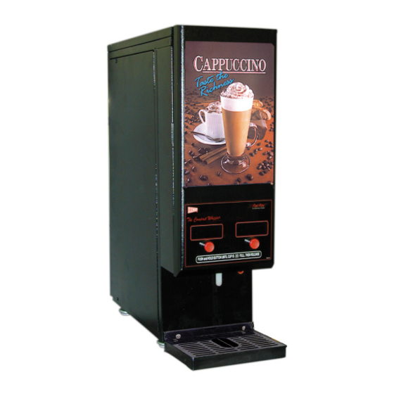
GB1HC-CP (shown)
Cecilware sells value... Worldwide
45 -05 20th Avenue, Long Island City, NY 11105
Tel: 1-718-932-1414
1-800-935-2211
Compact Cappuccino &
Hot Chocolate Dispensers
Models:
•GB1CP
•GB2CP
•GB3CP
•GB1HC-CP
•GB2HC-CP
•GB1HC-CP-PC*
•GB2HC-CP-PC*
Fax:
1-718-932-7860
E-mail: customer.service@cecilware.com
GB2-CP (shown)
OPERATIONAL MANUAL
NL05A May 2007
Advertisement
Table of Contents

Related Manuals for Cecilware GB1CP


Summary of Contents for Cecilware GB1CP
- Page 1 Compact Cappuccino & Hot Chocolate Dispensers GB1HC-CP (shown) Cecilware sells value... Worldwide 45 -05 20th Avenue, Long Island City, NY 11105 Tel: 1-718-932-1414 1-800-935-2211 E-mail: customer.service@cecilware.com Models: •GB1CP •GB2CP •GB3CP •GB1HC-CP •GB2HC-CP •GB1HC-CP-PC* •GB2HC-CP-PC* Fax: 1-718-932-7860 GB2-CP (shown) OPERATIONAL MANUAL...
-
Page 2: Description Of Components
Hot Chocolate Add an additional 2.5” when installing with legs. Add 2" for line cord and valve fitting clearance. Plumbing: ¼” water line required. Model No. Volts Phase GB1CP, GB2CP, GB3CP 120V GB1HC-CP, GB2HC-CP GB1HC-CP-PC*,•GB2HC-CP-PC* * Automatic Portion Control For Wiring, refer to Wiring Diagrams. See Electrical Data Label attached to the back of the unit for proper voltages, breaker sizes and electrical outlet requirements for each model number listed. -
Page 3: Installation Instructions
I. INSTALLATION INSTRUCTIONS This equipment is to be installed to comply with the applicable Federal, State, or local plumbing codes having jurisdiction. In addition: 1. A quick disconnect water connection or enough extra coiled tubing (at least 2x the depth of the unit) so that the machine can be moved for cleaning underneath. -
Page 4: Recommended Preventive Maintenance
ADJUSTMENTS A. WATER FLOW ADJUSTMENTS, FLOW RATE The Unit Is Factory Adjusted To Dispense Water At The Rate of 1 to 1.3 oz/ sec. To increase or decrease flow, proceed as follows: Remove Left side panel and locate Dispense Valve mounted on tank, with Flow Adjuster facing up, underneath cold water reservoir. -
Page 5: Components Test
COMPONENTS TEST A) Thermostat Adjustments: The Thermostat is factory set for proper dispense temperature of 190° F with the control shaft set to the maximum clockwise position. If field adjustments are needed proceed as follows: To DECREASE temperature, turn the control shaft slightly in the COUNTERCLOCKWISE direction. -
Page 6: Troubleshooting Guide
WARNING: To reduce the risk of electrical shock unplug the dispenser power cord before repairing or replacing any internal components of the unit.. Before any attempt to replace a component be sure to check all electrical connections for proper contact. PROBLEM PROBABLE CAUSE A Water supply OFF. -
Page 7: Cleaning And Sanitizing
CLEANING AND SANITIZING Sanitizing: All sanitizing agents in the food zone must comply with 21 CFR 178.1010. All food dispensing units should be sanitized periodically. All parts to be sanitized must be cleaned first. To prepare a sanitizing solution: Add 2 Tsp. Of Liquid Clorox Bleach (5.25% Concentration) To 1 gallon Of Water At Room Temperature (70°- 90°F). Note: Always start with a unopened bottle of Clorox Bleach since the solution from an opened bottle has a short life span. -
Page 8: Internal Components Identification
INTERNAL COMPONENTS IDENTIFICATION TANK ASSEMBLY SK89Q ITEM P/N QTY DESCRIPTION SK88A Tank Top L681A Thermostat & Probe M008A Thermostat Knob G267A Heater 120v 1700w MO18A Gasket, Tank Heater P446A 1/4-20x5/8 SS SL Hex Washer Hd Scr M461A Silicone Seal (.466 Id) K525A Elbow 90°... - Page 9 EXTERNAL COMPONENTS IDENTIFICATION ITEM P/N DESCRIPTION SS42A Top Cover SS51A Side Panels CD161 Hopper 8lb GB1 CD155 Hopper 4lb GB2, GB3 M705A Door Latch CD70A Product Guide GB1, GB3 CD234 Product Guide Right GB2 CD246 Product Guide Left GB2 CD374 Product Guide Right GB3 CD373 Product Guide Left GB3...
- Page 10 CECILWARE CORPORATION - WATER LEVEL CONTROL - WATER LEVEL PROBES WATER...
- Page 11 - WATER LEVEL CONTROL - WATER LEVEL PROBES WATER CECILWARE CORPORATION...
- Page 12 WATER INLET VALVE WATER LEVEL PROBES CECILWARE CORPORATION LIQUID LEVEL CONTROL WATER...
Need help?
Do you have a question about the GB1CP and is the answer not in the manual?
Questions and answers