Table of Contents
Advertisement
Quick Links
Advertisement
Table of Contents

Related Manuals for Ulvac UTM2300 Series


Summary of Contents for Ulvac UTM2300 Series
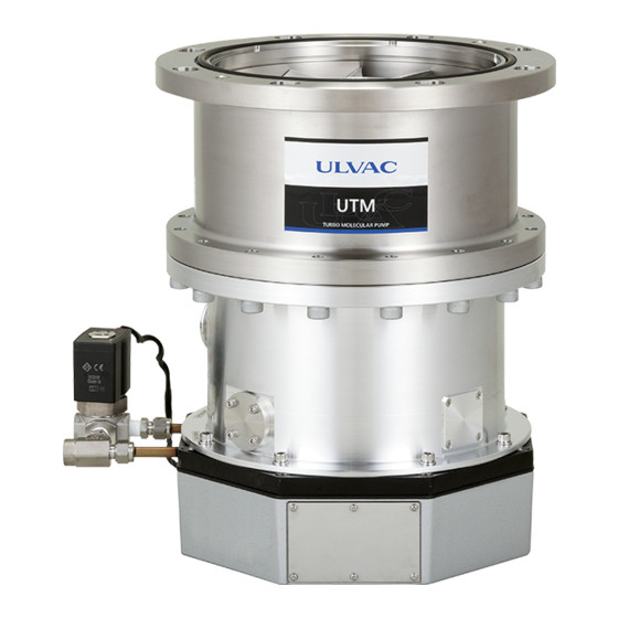
- Page 1 YK17-0012-102-00 (263-43466) INSTRUCTION MANUAL Turbo Molecular Pump Model UTM2300 Series Before using this product, be sure to read this operation manual. Keep this manual with care to use at any time. ULVAC, Inc. Components Division http://www.ulvac.co.jp/...
- Page 2 This page is intentionally left blank.
-
Page 3: Copyrights And Disclaimers
Every effort has been made to prepare an accurate and complete manual, but if an error or omission should be discovered, revisions might not be possible immediately. ULVAC does not take responsibility for any effects that may result from the use of this manual. Copyright 2017 ULVAC, Inc.All rights reserved. -
Page 4: Precautions For Safe Operation
WARNING Turbo molecular pump repair and/or power supply repair can be very hazardous. Only trained technicians who are authorized by ULVAC may do service of products. WARNING Neither overhaul nor modify the pump proper and power supply unit without admission. - Page 5 ・ Improper turbo molecular pump use may be hazardous to operator's health in applications not recommended or approved by ULVAC. In the event removal of the turbo molecular pump from an application is required, full protective measures including purging of the turbo molecular...
- Page 6 CAUTION After having operated the turbo molecular pump for evacuation of corrosive gas, keep the pump internal as vacuumed even after shutdown. Inflow of water content in the air to the pump internal would cause rapid corrosion trouble of the pump internals. The pump corrosion may result in damaging the vacuum vessel interior and other units, causing pressure fluctuation by stopping the pump and dispersal of parts.
-
Page 7: Operating Precautions
CAUTION When pump is removed from a equipment, drain the water from water pipe. If remained water leak from water pipe, pump body will be corroded. In the case of the specifications with the water valve, drain the water from water pipe during pump power on and water valve open. - Page 8 NOTICE Before touching the pump internals and the vacuum chamber, put a pair of nylon gloves without fail. Avoid direct touch with them. Internal contamination of the vacuum chamber or the pump would cause deterioration of adequate vacuuming performance. When using a hydraulic rotary pump with vibration of wide amplitude, as a backing vacuum pump, undertake proper anti-vibration measure.
-
Page 9: Explanation Of Label
(6) SECURITY Seal This label certificates that the product was made or maintained by ULVAC or by ULVAC authorized facility. In case "this label is removed" or "there is a mark showing once this label has been removed", ULVAC warranty shall not be applied to... -
Page 10: Location Of Label
○ Location of Label viii... -
Page 11: Table Of Contents
Table of contents Table of contents Introduction Copyrights and Disclaimers ....... . i Precautions for Safe Operation . -
Page 12: Table Of Contents
Table of contents Section 4 SPECIFICATIONS 4.1 Standard Specifications for Pump Unit....18 4.2 The Maximum Allowable Flow Rate ....21 4.3 Standards Fulfilled . - Page 13 Table of contents 6.5 Variable Speed Operation ......45 6.5.1 Outline..........45 6.5.2 Operation from Start-up to Low Speed Rotation.
- Page 14 Table of contents Section 9 TROUBLESHOOTING 9.1 Vacuum Pressure Rise......70 9.2 Abnormal Noise and/or Vibration .
-
Page 15: Section 1 Outline And Descriptions
OUTLINE AND DESCRIPTIONS 1.1 Outline 1.2 Descriptions 1.2.1 Outside Drawing of Pump Unit 1.2.2 Power Cable 1.2.3 Standard Accessories 1.2.4 Option 1.2.5 Document List... -
Page 16: Outline
SECTION 1 OUTLINE AND DESCRIPTIONS Outline The turbo molecular pump is a vacuum pump. The turbo molecular pump is used with a backing vacuum pump to create a high vacuum in a vacuum chamber. Typical Applications ; Semiconductor equipments, Industrial equipments, R&D applications, The other ultra high vacuum applications. -
Page 17: Descriptions
1.2 Descriptions Descriptions 1.2.1 Outside Drawing of Pump Unit Description Inlet flange ΦE ΦF n-Φd UTM2300A-MI-AVWX VG250 22.5 Φ320 Φ350 12-Φ13 UTM2300A-MI-BVWX UTM2300A-MI-AFWX ISO250F 17.6 Φ310 Φ335 12-Φ11 UTM2300A-MI-BFWX Fig.1-1 UTM2300 Series... -
Page 18: Power Cable
SECTION 1 OUTLINE AND DESCRIPTIONS 1.2.2 Power Cable One of followings. Description Notes 1 AC CABLE, 5 MT 2 AC CABLE, 10 MT 3 AC CABLE, 15 MT 4 AC CABLE, 20 MT ・Connector ・Clamp 5 AC CONNECTOR SET ・Core ・Assembling procedure 1.2.3 Standard Accessories Description Note... -
Page 19: Document List
1.2 Descriptions 1.2.4 Option Please select if necessary. Instruction Manual Description Note 1 Instruction manual for UTM2300 series Booklet English Instruction manual for Serial communication (for UTM2300/3400 English series) Booklet Gas Purge Adaptor Joint Orifice size Description 1 KF10 (Clamp / Centering with O-ring) Φ0.5 mm... - Page 20 1.2 Descriptions This page is intentionally left blank.
-
Page 21: Section 2 Identification And Function
IDENTIFICATION AND FUNCTION 2.1 Pump Main Unit 2.2 Control Panel 2.3 External I/F Panel... -
Page 22: Pump Main Unit
SECTION 2 IDENTIFICATION AND FUNCTION Pump Main Unit Fig.2-1 Pump Main Unit (1) INLET FLANGE ....... Inlet flange, joint the turbo molecular pump, VG250 and ISO250F are available. (2) PORT FOR GAS PURGE....Gas purge adaptor port, KF10, UJR 6.35, Swagelok Φ6.35 and 4-VCR are available. (Refer to Section 7 "GAS PURGE".) (3) OUTLET FLANGE ...... -
Page 23: Control Panel
2.2 Control Panel Control Panel Fig.2-2 Outline View of Control Panel (1) AC INPUT connector .......Power cable receptacle. (Refer to Section 5.2 "Connection of Power Cable".) (2) POWER Switch........Power switch. (3) START/STOP button .......Push to acceleration or deceleration. During LOCAL MODE, control by maintained push. (4) RESET button ........When occur ALARM or WARNING, after remedying the cause of the ALARM, an abnormal state is released by pushing button. -
Page 24: External I/F Panel
SECTION 2 IDENTIFICATION AND FUNCTION External I/F Panel Fig.2-3 I/F Panel (1) REMOTE connector ......Connector for remote-control. (Refer to Section 6.7 "Remote-control Connector".) (2) SERIAL connector ......Connector for RS-232C or RS-485 communication. (Refer to Section 6.8 "Communication Specifications".) (3) VALVE connector ......Water valve connector. (Refer to Section 5.3 "Preparation for Operation".) (Note 1) All interfaces are SELV (safety extra-low voltage). -
Page 25: Section 3 Construction And Principle
CONSTRUCTION AND PRINCIPLE 3.1 Pump Construction 3.2 Principle of Turbo Molecular Pumping 3.3 Controller... -
Page 26: Pump Construction
SECTION 3 CONSTRUCTION AND PRINCIPLE Pump Construction Fig. 3-1 is a sectional drawing of a magnetic bearing type turbo molecular pump. The built-in high frequency motor (1) is accelerated to the specified revolutions (speed) by the high frequency power supply unit. Rotor blades (3) are fitted onto the drive shaft (2) and the stator blades (4) are arranged in between the rotor blades. - Page 27 3.2 Principle of Turbo Molecular Pumping Fig.3-1 Pump Sectional Drawing (1) High frequency motor (6) Radial magnetic bearing (11) Outlet flange (2) Drive shaft (7) Axial magnetic bearing (12) Protective net (3) Rotor blade (8) Touch-down bearing (13) Cooling water pipeline (4) Stator blade (9) Gap sensor (14) Controller (5) Spacer...
- Page 28 SECTION 3 CONSTRUCTION AND PRINCIPLE The movement of an object has 6 degrees of freedom. Levitation can be achieved in a turbo molecular pump by controlling the following 5 degrees of freedom (excluding the rotational degree (Z axis) of freedom). rotational axis Parallel movement Radial displacement Axial displacement...
-
Page 29: Controller
3.3 Controller Controller This product has a controller comprising a magnetic bearing control system that levitates the rotors in a specific position inside the turbo molecular pump, a high frequency power supply system that rotates the rotor at a specific speed, and a pump temperature control system. The magnetic bearing control system levitates the rotor at a given position by using a gap sensor inside the pump to detect the rotor position and controlling the electromagnet current. - Page 30 3.3 Controller This page is intentionally left blank.
-
Page 31: Section 4 Specifications
SPECIFICATIONS 4.1 Standard Specifications for Pump Unit 4.2 The Maximum Allowable Flow Rate 4.3 Standards Fulfilled... -
Page 32: Standard Specifications For Pump Unit
Start-up time 9 minutes or less Mounting position In any desired direction (Note 5) Vibration level 0.01 μm or less (0-peak) (by ULVAC's method) Noise 60 dB(A) or less R ecommended flow rate of purge gas 30 mL/min (Note 3) - Page 33 4.1 Standard Specifications for Pump Unit If power interruption is 1 second or less, pre-interruption Instantaneous power interruption functions are maintained. If interruption exceeds 1 second, the (Note 6) brake is activated, which allows the pump to be restarted after resetting. This valve is closed during power supply OFF, and the coolant water is stopped.
- Page 34 SECTION 4 SPECIFICATIONS Use : Indoor, Altitude max : 2000 m, Installation conditions Overvoltage category III, Pollution degree 2 (Refer to UL/EN 61010-1 standard) IP classification 40 Operation : 10 to 40 degrees C. / Environmental temperatures Storage : -25 to 70 degrees C. (No dew condensation) Relative humidity 40 tso 80 %RH (Note 1) Do not use corrosive gasses because there is a possibility that the rotor blade is damaged...
-
Page 35: The Maximum Allowable Flow Rate
30 mL/min 1250 mL/min (Note 1) Consult your ULVAC representative before using gasses except shown in above table. (Note 2) mL/min : volume flow rate at 0 degrees C., 1 atm. (Compatible with SCCM.) (Note 3) The maximum allowable flow rate depends on the gas type, the Assuming the parts connected to the molecular pump inlet and the gas purge flow rate. - Page 36 4.3 Standards Fulfilled This page is intentionally left blank.
-
Page 37: Section 5 Installation
INSTALLATION 5.1 Installation 5.1.1 Pump Mounting Direction 5.1.2 Installation of the Pump 5.1.2.1 Instruction and Lifting Method 5.1.2.2 Installation of Turbo Molecular Pump 5.1.3 Example of Piping Connection 5.1.3.1 Connection of Exhaust Line 5.1.3.2 Connection of Cooling Water Line 5.2 Connection of Power Cable 5.3 Preparation for Operation 5.4 Interlock for Vacuum System 5.5 Notes on Transportation... -
Page 38: Installation
SECTION 5 INSTALLATION Installation 5.1.1 Pump Mounting Direction This turbo molecular pump can be installed in vertical, horizontal, inverted, or oblique position. The outlet port of the turbo molecular pump should face horizontally or vertically when installing the pump horizontally and obliquely. When an installation direction is non-appropriate, reliability of operation may deteriorate. -
Page 39: Installation Of The Pump
5.1 Installation 5.1.2 Installation of the Pump WARNING Do not operate the turbo molecular pump until safety is confirmed. ・ The rotor assembly of the turbo molecular pump rotates at high speed. Large rapid shutdown torque should be generated when abnormality occurs in the pump by any chance. Incidental accident will cause the pump to drop out and to make a catastrophe if the pump is fixed by insufficient method. - Page 40 SECTION 5 INSTALLATION NOTICE Before touching the pump internals and the vacuum chamber, put a pair of nylon gloves without fail. Avoid direct touch with them. Internal contamination of the vacuum chamber or the pump would cause deterioration of adequate vacuuming performance. When using a hydraulic rotary pump with vibration of wide amplitude, as a backing vacuum pump, undertake proper anti-vibration measure.
-
Page 41: Instruction And Lifting Method
5.1 Installation 5.1.2.1 Instruction and Lifting Method This product lift the pump in the manner shown in Fig. 5-2. Vacuum Vacuum chamber chamber PUMP PUMP Fig.5-2 Lifting Method Table 5-1 Eyebole Size Position Inlet flange Eyebolt size Number of eyebolts Remark VG250 Vertical ISO250F Not bundled items VG250... -
Page 42: Installation Of Turbo Molecular Pump
UTM2300 Series 46400 N•m (Note) Rapid shutdown torque is the typical value measured by the ULVAC’s test condition. The torque to transmit to host equipment might be different according to the rigidity of host equipment. Host equipment should be designed to have enough margins in strength. - Page 43 5.1 Installation Fig.5-5 How to Use of the Bolt Table 5-2 The Recommended Fixing Bolt Bolt-Nut (Half thread) Fixing method Only by the inlet flange Inlet flange VG250 ISO250F Bolt size, Quantity M12, 12 PC M10, 12 PC SCM435 (JIS G 4053 / ISO-683) Material Stainless steel or equivalent...
-
Page 44: Example Of Piping Connection
SECTION 5 INSTALLATION 5.1.3 Example of Piping Connection 5.1.3.1 Connection of Exhaust Line Connect a backing vacuum pump or its related pipe connection flange to the outlet flange of the pump. (Refer to Fig. 5-7) * marks are not attached to this turbo molecular pump set. Fig.5-7 Example of Exhaust Line When gas purge required, connect the gas purge pipeline to the gas purge port. -
Page 45: Connection Of Cooling Water Line
5.1 Installation 5.1.3.2 Connection of Cooling Water Line (1) Supply the coolant water to coolant water IN connection of the solenoid valve for the coolant water as shown in Fig. 5-8, and drain the cooling water pipe from coolant water OUT connection. The valve to isolate (Lockout / Tagout) cooling water should be installed at user equipment. -
Page 46: Connection Of Power Cable
SECTION 5 INSTALLATION Connection of Power Cable CAUTION The standard power input voltage of this product is 200 to 240 VAC ± 10 %. Connection of the control system to the incorrect input voltage can cause damage to the equipment. Supply the power via a circuit breaker (rating 15 A). - Page 47 5.2 Connection of Power Cable REFERENCE For the specified power voltage, refer to the side panel of the power supply unit. Fig.5-11 Power Cable Table 5-4 Power Cable CONNECTION Wire color of power cable Green/Yellow Black White Location...
-
Page 48: Preparation For Operation
SECTION 5 INSTALLATION Preparation for Operation (1) This product is a water cooled model. Always provide a flow of coolant water that meets the indicated specifications. (Note 1) (2) Make sure no water is leaking from the coolant lines. Do not spill coolant on the pump. (3) Confirm the cable from water valve is surely connected to VALVE connector of External I/F panel. -
Page 49: Interlock For Vacuum System
(an air suspension truck, for example). Especially when passing by rough road, we recommend that the product is transported keeping the packing condition when it ships from ULVAC. When the product is put on the high temperature / humidity environment for a long time, it causes the breakdown of the product due to corrosion of mechanical parts or performance loss of electrical parts. - Page 50 5.5 Notes on Transportation This page is intentionally left blank.
-
Page 51: Section 6 Operation
OPERATION 6.1 Overview 6.1.1 Introduction : Operation Modes 6.2 Startup Preparation 6.2.1 Start-up Preparation Sequence in LOCAL Mode 6.2.2 Start-up Preparation Sequence in REMOTE-control Connector 6.2.3 Start-up Preparation Sequence in Other Communication Means 6.3 Start-up 6.3.1 Start-up Sequence in LOCAL Mode 6.3.2 Start-up Sequence in REMOTE-control Connector 6.3.3 Start-up Sequence in Other Communication Means 6.4 Shutting Down 6.4.1 Preparations Prior to Shutting Down Operation 6.4.2 Shutting Down Sequence in LOCAL Mode... -
Page 52: Overview
SECTION 6 OPERATION Overview CAUTION Do not turn off the power during pump operation. If the power is turned off repeatedly, the touch-down bearing may need to be replaced. When the power is turned off during operation, levitation is maintained using regenerative power. After decelerating to a lower speed, levitation is stopped and the rotor is supported by the touch-down bearing. - Page 53 6.1 Overview Table 6-1 LOCAL and REMOTE Modes Mode Lamp state START/STOP procedure LOCAL POWER lamp flashes. The pump can be started or stopped by holding down the START/STOP button. REMOTE POWER lamp lights up. The pump can be started or stopped via a remote control RS-232C connector, serial connector (RS-232C, RS-485).
-
Page 54: Startup Preparation
SECTION 6 OPERATION Startup Preparation NOTICE When turning the POWER switch ON or OFF, a "clunk" sound may be heard from inside the pump. This sound is from the rotor inside the pump being levitated or de-levitated. This is normal. 6.2.1 Start-up Preparation Sequence in LOCAL Mode (1) Feed the cooling water into the cooling line. -
Page 55: Start-Up Preparation Sequence In Other Communication Means
6.2 Startup Preparation tart-up Preparation Sequence in Other Communication Means 6.2.3 S (1) Feed the cooling water into the cooling line. (2) Turn on the POWER switch and check that the POWER lamp. Under this condition, the rotor of the turbo molecular pump is levitated by the magnetic bearing. (3) Online command is demanded from the communication means and confirm the mode was switched to the communication means mode. -
Page 56: Start-Up
SECTION 6 OPERATION Start-up tart-up Sequence in LOCAL Mode 6.3.1 S (1) Start-up begins when the Section 6.2.1 "Start-up Preparation Sequence in LOCAL Mode" is complete. (2) Maintained push the START/STOP button (Fig. 2-2 (3)). (3) Pump acceleration starts. The ROTATION lamp (Fig. 2-2 (6)) lights and the STATUS (Fig. -
Page 57: Shutting Down
6.4 Shutting Down Shutting Down CAUTION After having operated the turbo molecular pump for evacuation of corrosive gas, keep the pump internal as vacuumed even after shutdown. Inflow of water content in the air to the pump internal would cause rapid corrosion trouble of the pump internals. The pump corrosion may result in damaging the vacuum vessel interior and other units, causing pressure fluctuation by stopping the pump and dispersal of parts. -
Page 58: Shutting Down Sequence In Local Mode
SECTION 6 OPERATION hutting Down Sequence in LOCAL Mode 6.4.2 S (1) Maintained push the START/STOP button (Fig. 2-2 (3)) and check that the STATUS green lamp (Fig. 2-2 (7)) is turned off. (2) Wait until the ROTATION lamp (Fig. 2-2 (6)) goes out. (3) Turn off the POWER switch. -
Page 59: Variable Speed Operation
6.5 Variable Speed Operation Variable Speed Operation CAUTION When using the variable speed function to change the pump rotation rate, use a rotation rate that does not cause resonance with other devices installed at the site. utline 6.5.1 O (1) The rotational speed settings function sets the rotational speed by selecting between the NORMAL speed mode or LOW SPEED mode. -
Page 60: Operation From Start-Up To Low Speed Rotation
SECTION 6 OPERATION peration from Start-up to Low Speed Rotation 6.5.2 O This is the procedure until low-speed rotation is achieved when the speed setting is made with the pump stopped. 6.5.2.1 REMOTE Operation (1) Start-up begins when the Section 6.2.2 "Start-up Preparation Sequence in REMOTE- control Connector"... -
Page 61: Operation From Rated Speed Rotation To Low Speed Rotation
6.5 Variable Speed Operation peration from Rated Speed Rotation to Low Speed Rotation 6.5.3 O The following procedure is used to change the rotation speed setting and operate in the low- speed mode when currently operating at the rated speed or accelerating at a speed greater than low speed rotation. -
Page 62: Operation From Low Speed Rotation To Rated Speed Rotation
SECTION 6 OPERATION peration from Low Speed Rotation to Rated Speed Rotation 6.5.4 O This is the procedure to select normal speed operation during low speed rotation. 6.5.4.1 REMOTE Operation (1) Cancel the "LOW SPEED" signal (Refer to Table 6-4) inputted in the remote-control connector. -
Page 63: Software Operation
6.6 Software Operation Software Operation NOTICE Settings data can be read and written via serial interface, but cannot be read or written via remote control connector. Software functions are indicated in Table 6-2 below. Table 6-2 Software Operating Functions Function Descripition Status Operation mode LOCAL, REMOTE or the other communication means... - Page 64 SECTION 6 OPERATION (Note 1) List of run status. STATUS Descripition NORMAL Rotating at rated rotation speed ACCELERATION Accelerating BRAKE Decelerating STOP Stopped E-STOP Alarm is active (stopped) E-BRAKE Alarm is active (decelerating) E-IDLE Alarm is active (coasting motor is off)
-
Page 65: Remote-Control Connector
6.7 Remote-control Connector Remote-control Connector pecification 6.7.1 S This turbo molecular pump is provided with remote-control connector for connection with remote operation, ALARM signals, etc. (Refer to Fig. 6-2, Fig. 6-3, and Table 6-3) For connection with this connector, cable with shield is necessary. The shield of the cable should be connected to case. -
Page 66: Pin Assignment
SECTION 6 OPERATION in Assignment 6.7.2 P Table 6-4 Remote-control Signals Pin No. Operation Electric Name (Note 1) (Note 2) spec Starting operation on short-circuiting between START GND and pin No. 2. (Note 3) Pump stop by opening GND and pin No. 3. STOP (Note 3) (Note 5) Contact... -
Page 67: Connector
RS-XXX using hardware interlock. (Note 1) When set to EI-03, behavior of remote-control signals is the same as ULVAC Turbo Molecular Pump power supply "EI-xx03", "EI-Dxx03" and "EI-R04" series. (Note 2) When set to SEMI E74, behavior of remote-control signals conform to SEMI E74 standard "Specification for vacuum Pump Interface-Turbo Molecular Pumps". -
Page 68: Communication Specifications
SECTION 6 OPERATION Communication Specifications 6.8.1 RS-232C 6.8.1.1 Transfer Specifications Interface RS-232C Synchronous system Asynchronous Transmission rate 9600 bps (fixed) Start bit : 1 Character Data bits : 8 configuration Parity : None Stop bit : 1 Flow control None 6.8.1.2 Connector Specifications Connector SERIAL connector (shared with RS-485) Connector type... -
Page 69: Transfer Specifications
6.8 Communication Specifications a. Cable wiring connections for 9-pin connector cables. Fig.6-5 Example of RS-232C Cable Wiring Connections 6.8.2 RS-485 6.8.2.1 Transfer Specifications Interface RS-485 (2-wire, half duplex) Synchronous system Asynchronous Transmission rate 9600 bps (fixed) Start bit : 1 Character Data bits : 8 configuration Parity : None Stop bit : 1... -
Page 70: Cable
SECTION 6 OPERATION 6.8.2.3 CABLE (1) Cable connection T u r b o M o l e c u l a r P u m p N o . 1 COMPUTER A(+) 120Ω B(-) T u r b o M o l e c u l a r P u m p N o . -
Page 71: Connector
6.8 Communication Specifications (4) Cable length Connection cables can be extended up to 1.2 kilometers, but may be subjects to errors depending on actual operational environment. 6.8.3 Connector Fig.6-7 Serial Connector Pin Configuration (Figure where connector of panel was viewed from the front) NOTICE Serial communication specifications conform to RS-232C and RS-485. - Page 72 6.8 Communication Specifications This page is intentionally left blank.
-
Page 73: Section 7 Gas Purge
GAS PURGE... - Page 74 SECTION 7 GAS PURGE This product includes a port for purging gasses in optional specification (Fig. 2-1 (2)). Though not necessary for normal evacuation, use it to inject purging gas to increase maximum allowable flow rate. A purge gas flow rate 30 mL/min is appropriate. Be sure not to use the non-chemical type pumps to exhaust of corrosive gasses such as chlorine type or fluorine type.
-
Page 75: Section 8 Turbo Molecular Pump Recondition
TURBO MOLECULAR PUMP RECONDITION 8.1 Recommended Maintenance Intervals 8.2 Turbo Molecular Pump Decontamination 8.3 Touch-down Bearing Replacement 8.4 Check of the Rotor Blades 8.5 Power Supply Unit Parts Replacement 8.6 Turbo Molecular Pump Return Request... -
Page 76: Recommended Maintenance Intervals
SECTION 8 TURBO MOLECULAR PUMP RECONDITION Recommended Maintenance Intervals It is different for deterioration progress speed of each part changes greatly by pump condition. Refer to the following list as overhaul of each process. These are not terms of warranty. Recommended Process maintenance intervals Non-active gas (Sputtering, Evaporation and so... -
Page 77: Turbo Molecular Pump Decontamination
Touch-down Bearing Replacement The touch-down bearing (Fig. 3-1 (8)) is the only component of ULVAC's turbo molecular pump that is subjected to friction and wear, normally occurring only during electrical power failure. Repeated and/or frequent rotor touch down will cause wear and bigger rotational resistance and require replacement of touch down bearings. -
Page 78: Power Supply Unit Parts Replacement
To obtain ensure the pump and power supply unit operate safely and perform as designed, have parts that exceed their expected service life be replaced by a ULVAC service representative or an ULVAC authorized service provider. Table 8-1 Estimated Service Life for Parts... -
Page 79: Turbo Molecular Pump Return Request
Overhaul, re-manufacturing, refurbishing, or repair of the turbo molecular pump system should always be performed by ULVAC or an approved service company. (A copy of this from is printed at the end of this manuals "Repair of the Turbo Molecular Pump") The following precautions are required before forwarding the turbo molecular pump to ULVAC or an approved service company for all service related requests. - Page 80 SECTION 8 TURBO MOLECULAR PUMP RECONDITION CAUTION When pump is removed from a equipment, drain the water from water pipe. If remained water leak from water pipe, pump body will be corroded. In the case of the specifications with the water valve, drain the water from water pipe during pump power on and water valve open.
- Page 81 When the pump is returned, please pack it surely so as not to damage it by the impact, the vibration, and the high temperature and humidity environment, etc. from the outside. Please use the packing materials which were used at shipment from ULVAC, or use the packing materials having a same quality or better.
- Page 82 8.6 Turbo Molecular Pump Return Request This page is intentionally left blank.
- Page 83 TROUBLESHOOTING 9.1 Vacuum Pressure Rise 9.2 Abnormal Noise and/or Vibration 9.3 Nothing Happens After an Operation is Made 9.4 Power Failures 9.4.1 Power Failure Counter-operation 9.5 Alarm Detection Capabilities 9.5.1 Movement in Alarm Detection Capabilities (ALARM) 9.5.2 Movement in Alarm Detection Capabilities (WARNING) 9.5.3 Reset Procedure...
-
Page 84: Vacuum Pressure Rise
SECTION 9 TROUBLESHOOTING Vacuum Pressure Rise A rapid rise of vacuum pressure in the turbo molecular pump causes the internal motor of the turbo molecular pump to start braking and the STATUS orange lamp lights. Do not suddenly increase the pressure or let atmospheric air enter the pump during pump operation. -
Page 85: Nothing Happens After An Operation Is Made
9.3 Nothing Happens After an Operation is Made Nothing Happens After an Operation is Made Table 9-1 Nothing Happens After an Operation is Made Problem Possible causes Corrective action Section Power ON/OFF switch in Electrical power cable Properly connect the electrical power the ON position but the not properly connected. -
Page 86: Power Failures
Period of time before support Pump model by touchdown bearing by touchdown bearing (Note 1) UTM2300 Series 7500 rpm 9 minutes or less (Note 1) The time is typical for regenerative braking from the rated speed. Actual time will vary depending on vacuum conditions inside the pump and the rotational... -
Page 87: Power Failure Counter-Operation
9.4 Power Failures 9.4.1 Power Failure Counter-operation Table 9-3 shows the counter-operations against power interruption which occurred while the pump rotor is normally rotating. Table 9-3 Counter-operations Against Power Supply Failure Interruption time 1 second or less (Note 1) Over 1 second (Note 1) Interrupt/re-supply During interruption After re-supply... -
Page 88: Alarm Detection Capabilities
SECTION 9 TROUBLESHOOTING Alarm Detection Capabilities NOTICE Alarm history data can be read via serial interface, but cannot be read via remote control connector. The fault detection functions shown in Table 9-6 "Table of Alarms" and Table 9-7 "Table of Warnings" are incorporated for protection in the event of a problem with the turbo molecular pump or power supply unit. - Page 89 TD COUNTER LIMIT The number of high The touch-down bearing may have PF COUNTER LIMIT speed or power failure deteriorated. Consult ULVAC or an touch-downs has approved service company regarding exceeded the replacement of the touch-down prescribed number. bearing.
- Page 90 SECTION 9 TROUBLESHOOTING Alarm Sec- Alarm name Possible cause Remedy code tion EI:DEW ERROR Internal condensation Check that the ambient temperature and humidity around the pump and the temperature of cooling water are within the specified range. Check there are no solids piled up in the water valve.
- Page 91 9.5 Alarm Detection Capabilities Table 9-5 If the STATUS Orange Lamp Flashes Alarm Sec- Alarm name Possible cause Remedy code tion TMP:VALVE WARN Cable of water valve is Confirm the cable from water valve is no connected surely connected to VALVE connector correctly.
- Page 92 SECTION 9 TROUBLESHOOTING Table 9-6 Table of Alarms Alarm Alarm name Possible cause Protective action code Counts of the high speed touch-down counter Start-up impossible TD COUNTER LIMIT exceeded the specified number. (detected during power supply self- Counts of the power failure touchdown counter PF COUNTER LIMIT diagnostics) exceeded the specified number.
- Page 93 9.5 Alarm Detection Capabilities Alarm Alarm name Possible cause Protective action code MB:VIBRATION1 X1 Excessive magnetic bearing vibration. Deceleration MB:VIBRATION1 Y1 MB:VIBRATION1 X2 MB:VIBRATION1 Y2 MB:VIBRATION1 Z MB:SENSOR ERR. X1 Abnormal output signal from the magnetic bearing sensor. MB:SENSOR ERR. Y1 MB:SENSOR ERR.
- Page 94 SECTION 9 TROUBLESHOOTING Table 9-7 Table of Warnings Alarm Alarm name Possible cause Protective action code TMP:VALVE WARN Abnormal coolant valve Operation continued. Operation continued. EI:DEW WARN Dew warning Water valve is closed. EI:CONT.TEMP.WARN Increased temperature inside power supply unit. Operation continued. MB:SELFCHECK X1 Results of magnetic bearing sensor self- Operation is possible...
- Page 95 WARRANTY CLAUSES...
-
Page 96: Warranty Clauses
○ Response Procedure a) Domestic business in Japan : ULVAC send a replacement or Buyer return the defective items to ULVAC, Inc. or to the Nearest ULVAC Techno, Ltd. for repair. If field service is required, Buyer shall ask ULVAC, Inc. -
Page 97: Disclaimer
The "SECURITY seal" certificates that the product was made or maintenanced by ULVAC or by ULVAC authorized facility. In case "this label is removed" or "there is a mark showing once this label has been removed", ULVAC warranty shall not be applied to the product. - Page 98 This page is intentionally left blank.
- Page 99 Index Index touch-down bearing ......13 AC INPUT connecter ......9 UL ......... 21 backing vacuum pump ......8 VALVE connector ......10、34 cooling water ......8、31 gas purge ........18 inlet flange ....... 8、13 NET lamp ........9 noise ........18 outlet flange ......
- Page 100 Index This page is intentionally left blank. Index-2...
- Page 101 ULVAC service center or sales office prior to shipment. Please consult with your closest local ULVAC service center or sales office if our components are used with toxic gases or contaminated with reactive products or substances produced by reaction.
- Page 102 株式会社アルバック http://www.ulvac.co.jp/ サービス拠点一覧 http://www.ulvac.co.jp/support̲info/service/ 販売拠点一覧 http://www.ulvac.co.jp/support̲info/sales̲office/ 株式会社アルバック 規格品事業部 神奈川県茅ケ崎市萩園2500 TEL:0467-89-2261 アルバック販売株式会社 本社(東京) 東京都港区港南2-3-13 TEL:03-5769-5511 ulvac . co . jp アルバック販売株式会社 大阪支店 大阪府大阪市淀川区宮原3-3-31 TEL:06-6397-2286 ULVAC ,Inc. http://www.ulvac.co.jp/en/ Service Centers http://www.ulvac.co.jp/en/support/service-center/ Sales Offices http://www.ulvac.co.jp/en/support/sales-offices/ ULVAC, Inc. Components Division 2500 Hagisono, Chigasaki, Kanagawa, Japan TEL: +81-467-89-2261 ulvac . co . jp / en rev4.0...
Need help?
Do you have a question about the UTM2300 Series and is the answer not in the manual?
Questions and answers