Subscribe to Our Youtube Channel
Summary of Contents for Ulvac ULK-10A
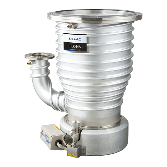
- Page 1 SK00- 4802-DC-002-01 No.090317 Heater Replacement Procedure Oil Diffusion Pump Model ULK-10A ULK-14A Components Division, ULVAC, Inc. http://www.ulvac.co.jp/...
-
Page 2: Preface
If you are not experienced in disassembly and reassembly of high vacuum pumps, contact your local ULVAC service station. Before replacement of the heater Disassembly of a pump used for exhausting toxic gas or active gas can be dangerous. -
Page 3: Table Of Contents
SK00- 4802-DC-002-01 No.090317 Contents Preface ..........................i Worker’s requirements ....................i Before replacement of the heater ..............i Parts used ......................1 1.1. Table of Major Parts .................. 1 1.2. Table of Replacement Parts ..............1 1.3. Bolts used ...................... 2 1.4. Miscellaneous .................... -
Page 4: Parts Used
SK00- 4802-DC-002-01 No.090317 1. Parts used 1.1. Table of Major Parts Description Quantity Check 1. Heater 1 pc. Boiler cover (with terminal box) 1 pc. Boiler cover 1 pc. Heater (terminal) cover 1 pc. Heat-resistant heat shrinkable tube 2 pcs. 15mm ID ×... -
Page 5: Bolts Used
M5 × 10 Spring washer M5 2 pcs. Plain washer M5 2 pcs. 1.4. Miscellaneous Quantity or size Description ULK-10A ULK-14A Check Working fluid ULVOIL 800 cc 1,500 cc D-11 or D-31 Intake port gasket 8 mm × 8 mm 8 mm ×... -
Page 6: Tools To Use
SK00- 4802-DC-002-01 No.090317 2. Tools to use 2.1. Table of Working Tools Photo Description Photo Description Torque wrench Heat-resistant 5 N m gloves Spanner 10: 2 pcs. 5 : 1 pc. Protective gloves Philips Box 10 mm screwdriver Shockless Spatula hammer Pliers Scraper... -
Page 7: Removing The Heater
SK00- 4802-DC-002-01 No.090317 3. Removing the Heater Power Supply wiring <Dismantling> ● Be sure to cut off the electricity before starting install or dismantling operation. WARNING Cooling water piping<Detaching> ● Should you remove the Coolant joint immediately after having stopped the Pump, there is a risk that the coolant remained inside the Pump comes to a boil and jets out. - Page 8 SK00- 4802-DC-002-01 No.090317 Move the pump to a place suited to working. Before removing the heater, make sure on a surface thermometer or the like that the working fluid temperature has lowered to near ambient temperature. Drain working fluid and remove the jet. For the disassembly and reassembly of the jet, refer to the instruction manual.
-
Page 9: Installing The Heater
SK00- 4802-DC-002-01 No.090317 Disassemble the heater in decreasing order of the numbers in the figure below. For reassembly, reverse the order. Fig.Removing the heater 4. Installing the Heater Take care against electric shock and burn. Energize the heater with 100V power to preheat it to 90°C. - Page 10 SK00- 4802-DC-002-01 No.090317 Take care against electric shock and burn. Wearing heat-resistant gloves, install the heater that has been preheated to 90°C. Turn off the power before installing the heater. Place the heater in a position where it is at approximate middle of the oil filling/draining port and fix the bolts and nuts.
- Page 11 SK00- 4802-DC-002-01 No.090317 (8) Temporarily install the boiler cover when the heater temperature has come down to ambient. Adjust the boiler cover and heater terminal positions. Adjust the heater terminal position so that it is at the center of the hole of the boiler cover.
- Page 12 SK00- 4802-DC-002-01 No.090317 (14) Attach the bent heater lead to the heater terminal using a spring washer, plain washer and nut so that it is upside (reverse to the oil filling/draining port) when the heater lead is attached. (15) Insert the heat-resistant thermal shrinkage tube into the heater terminal. Here, insert the heat-resistant thermal shrinkage tube into the glass wool tube installed by step (11) above.
- Page 13 SK00- 4802-DC-002-01 No.090317 (17) Install the boiler cover in position. Here, install the boiler cover in such way that the heater terminal is at the center of the hole in the boiler cover. (18) Make sure that the insulation resistance between the heater terminal and the boiler cover is 10 MΩ...


Need help?
Do you have a question about the ULK-10A and is the answer not in the manual?
Questions and answers