
Related Manuals for ProSoft Technology inRAX MVI69-S3964R


Summary of Contents for ProSoft Technology inRAX MVI69-S3964R
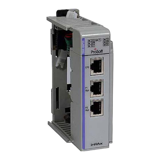
- Page 1 MVI69-S3964R CompactLogix or MicroLogix Platform Siemens 3964R Protocol 10/31/2008 USER MANUAL...
-
Page 2: Please Read This Notice
Under no conditions will ProSoft Technology be responsible or liable for indirect or consequential damages resulting from the use or application of the product. Reproduction of the contents of this manual, in whole or in part, without written permission from ProSoft Technology is prohibited. -
Page 3: Prosoft® Product Documentation
ProSoft® Product Documentation In an effort to conserve paper, ProSoft Technology no longer includes printed manuals with our product shipments. User Manuals, Datasheets, Sample Ladder Files, and Configuration Files are provided on the enclosed CD and are available at no charge from our web site: http://www.prosoft-technology.com Printed documentation is available for purchase. -
Page 5: Table Of Contents
Adding the Module to an Existing MicroLogix Project..........40 Diagnostics and Troubleshooting Reading Status Data from the Module ..............43 LED Status Indicators....................53 Reference Product Specifications..................... 55 Functional Overview....................57 Cable Connections ....................65 Reference Documents..................... 69 ProSoft Technology, Inc. Page 5 of 80 October 31, 2008... - Page 6 Status Data ......................69 Error Codes......................70 Support, Service & Warranty How to Contact Us: Technical Support..............71 Return Material Authorization (RMA) Policies and Conditions ....... 72 LIMITED WARRANTY .................... 74 Index Page 6 of 80 ProSoft Technology, Inc. October 31, 2008...
-
Page 7: Guide To The Mvi69-S3964R User Manual
(page 57) Functional Overview Product Glossary Specifications (page → Support, Service, and Support, Service This section contains Support, Service and Warranty and Warranty (page Warranty information. Index Index of chapters. ProSoft Technology, Inc. Page 7 of 80 October 31, 2008... - Page 8 MVI69-S3964R ♦ CompactLogix or MicroLogix Platform Start Here Siemens 3964R Protocol Page 8 of 80 ProSoft Technology, Inc. October 31, 2008...
-
Page 9: Start Here
1769-L23E-QBFC1B = 450mA at 5Vdc (no MVI69 module can be used with this processor) Rockwell Automation RSLogix 5000 (CompactLogix) or RSLogix 500 (MicroLogix) programming software Rockwell Automation RSLinx communication software ProSoft Technology, Inc. Page 9 of 80 October 31, 2008... -
Page 10: Package Contents
RS422 or RS485 Connections to Port 1 and 2 of the Module ProSoft Contains sample programs, utilities and Solutions CD documentation for the MVI69-S3964R module. If any of these components are missing, please contact ProSoft Technology Support for replacement parts. Page 10 of 80 ProSoft Technology, Inc. October 31, 2008... -
Page 11: Install Prosoft Configuration Builder Software
You must install the ProSoft Configuration Builder (PCB) software in order to configure the MVI69-S3964R module. You can always get the newest version of ProSoft Configuration Builder from the ProSoft Technology web site. To install ProSoft Configuration Builder from the ProSoft Web Site Open your web browser and navigate to http://www.prosoft-... -
Page 12: Setting Jumpers
"write protected" mode, the Setup pins are not connected, and the module's firmware cannot be overwritten. Do not jumper the Setup pins together unless you are directed to do so by ProSoft Technical Support. Page 12 of 80 ProSoft Technology, Inc. October 31, 2008... -
Page 13: Install The Module In The Rack
Move the module back along the tongue-and-groove slots until the bus connectors on the MVI69 module and the adjacent module line up with each other. ProSoft Technology, Inc. Page 13 of 80 October 31, 2008... - Page 14 Push the module's bus lever back slightly to clear the positioning tab and move it firmly to the left until it clicks. Ensure that it is locked firmly in place. Close all DIN rail latches. Page 14 of 80 ProSoft Technology, Inc. October 31, 2008...
- Page 15 MVI69-S3964R ♦ CompactLogix or MicroLogix Platform Siemens 3964R Protocol Press the DIN rail mounting area of the controller against the DIN rail. The latches will momentarily open and lock into place. ProSoft Technology, Inc. Page 15 of 80 October 31, 2008...
-
Page 16: Connect Your Pc To The Processor
Connect the right-angle connector end of the cable to your controller at the communications port. Connect the straight connector end of the cable to the serial port on your computer. Page 16 of 80 ProSoft Technology, Inc. October 31, 2008... -
Page 17: Download The Sample Program To The Processor
Click OK to switch the processor from Program mode to Run mode. Note: If you receive an error message during these steps, refer to your RSLogix documentation to interpret and correct the error. ProSoft Technology, Inc. Page 17 of 80 October 31, 2008... - Page 18 Note: If the list of configured drivers is blank, you must first choose and configure a driver from the Available Driver Types list. The recommended driver type to choose for serial communication with the processor is "RS-232 DF1 Devices". Page 18 of 80 ProSoft Technology, Inc. October 31, 2008...
- Page 19 If you are still unable to auto-configure the port, refer to your RSLinx documentation for further troubleshooting steps. ProSoft Technology, Inc. Page 19 of 80 October 31, 2008...
-
Page 20: Connect Your Pc To The Module
Attach both cables as shown. Insert the RJ45 cable connector into the Configuration/Debug port of the module. Attach the other end to the serial port on your PC or laptop. Page 20 of 80 ProSoft Technology, Inc. October 31, 2008... -
Page 21: Configuring The Mvi69-S3964R Module
PCB is not only a powerful solution for new configuration files, but also allows you to import information from previously installed (known working) configurations to new projects. ProSoft Technology, Inc. Page 21 of 80 October 31, 2008... - Page 22 Your first task is to add the MVI69-S3964R module to the project. Use the mouse to select "Default Module" in the tree view, and then click the right mouse button to open a shortcut menu. Page 22 of 80 ProSoft Technology, Inc. October 31, 2008...
- Page 23 Double-click the Default Module icon to open the Choose Module Type dialog box. On the Choose Module Type dialog box, select the module type. Open the Project menu and choose Location. On the Location menu, choose Add Module. ProSoft Technology, Inc. Page 23 of 80 October 31, 2008...
- Page 24 Select the object, and then click the right mouse button to open a shortcut menu. From the shortcut menu, choose Rename. Type the name to assign to the object. Click away from the object to save the new name. Page 24 of 80 ProSoft Technology, Inc. October 31, 2008...
- Page 25 On the View Configuration window, open the File menu, and choose Print. This action opens the Print dialog box. On the Print dialog box, choose the printer to use from the dropdown list, select printing options, and then click OK. ProSoft Technology, Inc. Page 25 of 80 October 31, 2008...
-
Page 26: Module]
: 1000 #Number of mSec to wait for ACK (Default 1000ms) Setup Attempts 1 #Number of times to try to connect to CP (Default 6) Transmit Attempts : 1 #Number of times to try to transmit to CP (Default 6) Page 26 of 80 ProSoft Technology, Inc. October 31, 2008... - Page 27 0 to 65535 milliseconds This parameter sets the number of milliseconds to delay after the last byte of data is sent before the RTS modem signal will be set low. ProSoft Technology, Inc. Page 27 of 80 October 31, 2008...
- Page 28 Number of milliseconds to wait for ACK. The default is 1000 ms. 2.4.13 Setup Attempts Number of times to try to connect to CP (Default 6) 2.4.14 Transmit Attempts Number of times to try to transmit to CP (Default 6) Page 28 of 80 ProSoft Technology, Inc. October 31, 2008...
-
Page 29: Download The Project To The Module
The module will perform a platform check to read and load its new settings. When the platform check is complete, the status bar in ProSoft Configuration Builder will be updated with the message "Module Running". ProSoft Technology, Inc. Page 29 of 80 October 31, 2008... - Page 30 MVI69-S3964R ♦ CompactLogix or MicroLogix Platform Configuring the MVI69-S3964R Module Siemens 3964R Protocol Page 30 of 80 ProSoft Technology, Inc. October 31, 2008...
-
Page 31: Ladder Logic
ATTENTION: You must be trained in programming and operating Rockwell Automation 1769-L series controllers and CompactLogix or MicroLogix environment. Otherwise, incorrect use may lead to personal injury or death, property damages or economic loss. ProSoft Technology, Inc. Page 31 of 80 October 31, 2008... - Page 32 During the processes described above additional status/error messages may be transferred from the MVI69-S3964R to the CompactLogix or MicroLogix processor (refer to Module Status Data Table (page 69)). Refer to Error Processing for more information. Page 32 of 80 ProSoft Technology, Inc. October 31, 2008...
-
Page 33: Module Data Object
The object has the following structure. This object contains objects that define user and status data related to the module. Each of these object types is discussed in the following topics of the document. ProSoft Technology, Inc. Page 33 of 80 October 31, 2008... - Page 34 "real-time rate". Refer to Module Status Data Table (page 69) for a complete listing of the data stored in this object. 3.2.2 Backplane Object Page 34 of 80 ProSoft Technology, Inc. October 31, 2008...
- Page 35 This data object stores the variables required for the data transfer between the processor and the MVI69-S3964R module. The structure of the object is shown in the following illustration. 3.2.4 Port Errors ProSoft Technology, Inc. Page 35 of 80 October 31, 2008...
-
Page 36: Commands
3.3.2 9999 Cold Boot The SLC processor can request a cold boot operation by the module by placing a value of 9999 in the M1 register 6800 (Command Control Register). Page 36 of 80 ProSoft Technology, Inc. October 31, 2008... -
Page 37: Adding The Module To An Existing Compactlogix Project
Add the MVI69-S3964R module to the project. Right-click the mouse button on the I/O Configuration option in the Controller Organization window to display a pop-up menu. Select the New Module option from the I/O Configuration menu. ProSoft Technology, Inc. Page 37 of 80 October 31, 2008... - Page 38 You must select the Comm Format as Data - INT in the dialog box, otherwise the module will not communicate over the backplane of the CompactLogix rack. Page 38 of 80 ProSoft Technology, Inc. October 31, 2008...
- Page 39 Copy the User Defined Data Types from the sample program. Copy the Ladder Rungs from the sample program. Save and Download the new application to the controller and place the processor in run mode. ProSoft Technology, Inc. Page 39 of 80 October 31, 2008...
-
Page 40: Adding The Module To An Existing Micrologix Project
On the I/O Configuration dialog box, select "Other - Requires I/O Card Type ID" at the bottom of the list in the right pane, and then double-click to open the Module dialog box. Page 40 of 80 ProSoft Technology, Inc. October 31, 2008... - Page 41 Download the new application to the controller and place the processor in run mode. If you encounter errors, refer to Diagnostics and Troubleshooting (page 43) for information on how to connect to the module's Config/Debug port to use its troubleshooting features. ProSoft Technology, Inc. Page 41 of 80 October 31, 2008...
- Page 42 MVI69-S3964R ♦ CompactLogix or MicroLogix Platform Ladder Logic Siemens 3964R Protocol Page 42 of 80 ProSoft Technology, Inc. October 31, 2008...
-
Page 43: Diagnostics And Troubleshooting
You can connect directly from your computer's serial port to the serial port on the module to view configuration information, perform maintenance, and send (upload) or receive (download) configuration files. ProSoft Technology recommends the following minimum hardware to connect your computer to the module: 80486 based processor (Pentium preferred) 1 megabyte of memory At least one UART hardware-based serial communications port available. - Page 44 To connect to the module's Configuration/Debug serial port: Start PCB program with the application file to be tested. Right click over the module icon. On the shortcut menu, choose Diagnostics. Page 44 of 80 ProSoft Technology, Inc. October 31, 2008...
- Page 45 On computers with more than one serial port, verify that your communication program is connected to the same port that is connected to the module. If you are still not able to establish a connection, contact ProSoft Technology for assistance.
- Page 46 Only use these commands if you are specifically directed to do so by ProSoft Technology Technical Support staff. Some of these command keys are not listed on the menu, but are active nevertheless. Please be careful when pressing keys so that you do not accidentally execute an unwanted command.
- Page 47 Press [Y] to confirm the file transfer, and then follow the instructions on the terminal screen to complete the file transfer process. After the file has been successfully downloaded, you can open and edit the file to change the module's configuration. ProSoft Technology, Inc. Page 47 of 80 October 31, 2008...
- Page 48 Only use these commands if you are specifically directed to do so by ProSoft Technology Technical Support staff. Some of these command keys are not listed on the menu, but are active nevertheless. Please be careful when pressing keys so that you do not accidentally execute an unwanted command.
- Page 49 And so on. The total number of register pages available to view depends on your module's configuration. Displaying the Current Page of Registers Again This screen displays the current page of 100 registers in the database. ProSoft Technology, Inc. Page 49 of 80 October 31, 2008...
- Page 50 Press [A] to display the data on the current page in ASCII format. This is useful for regions of the database that contain ASCII data. Returning to the Main Menu Press [M] to return to the Main Menu. Page 50 of 80 ProSoft Technology, Inc. October 31, 2008...
- Page 51 Use this command to display the configuration and statistics of the backplane data transfer operations between the module and the processor. The information on this screen can help determine if there are communication problems between the processor and the module. ProSoft Technology, Inc. Page 51 of 80 October 31, 2008...
- Page 52 Returning to the Main Menu Press [M] to return to the Main Menu. Viewing Configuration Information Press [C] to view configuration information for the selected port, protocol, driver or device. Page 52 of 80 ProSoft Technology, Inc. October 31, 2008...
-
Page 53: Led Status Indicators
Technology, as this is not a user serviceable item. If the APP, BP ACT and OK LEDs blink at a rate of every one-second, this indicates a serious problem with the module. Call ProSoft Technology support to arrange for repairs. - Page 54 Technology Support. 4.2.2 Troubleshooting Use the following troubleshooting steps if you encounter problems when the module is powered up. If these steps do not resolve your problem, please contact ProSoft Technology Technical Support. Processor Errors Problem Description Steps to take...
-
Page 55: Reference
Status Data.................... 69 Error Codes ................... 70 Product Specifications The MVI69 S3964R module from ProSoft Technology allows point-to-point communication between a CompactLogix processor and a partner with 3964R (with or without RK512) communication capability. The 3964R protocol was designed by Siemens for bi-directional data communication through a point-to-point connection. - Page 56 While in 3964R with RK512 mode on PRT1 and PRT2, evaluation of the header information DB (data block), DW (data word) and coordination bytes 9 and 10 is possible Communication activity and diagnostics are available through LEDs and acknowledgment telegrams Page 56 of 80 ProSoft Technology, Inc. October 31, 2008...
-
Page 57: Functional Overview
You should have sufficient knowledge about the 3964R protocol in order to understand the operation of the driver for the MVI69-S3964R and to make efficient use of the example programs. ProSoft Technology, Inc. Page 57 of 80 October 31, 2008... - Page 58 Set up the communication interface for the debug/configuration port When this initialization procedure is complete, the module will begin communicating with other nodes on the network, depending on the configuration. Page 58 of 80 ProSoft Technology, Inc. October 31, 2008...
- Page 59 Main Logic Loop Upon completing the power up configuration process, the module enters an infinite loop that performs the functions shown in the following diagram. Backplane Data Transfer Receive from CP ProSoft Technology, Inc. Page 59 of 80 October 31, 2008...
- Page 60 Port 2 Block 3 Block 4 Block 5 9011 First block for port 1 9921 Second and last block for port 1 9912 First and last block for port 2 Page 60 of 80 ProSoft Technology, Inc. October 31, 2008...
- Page 61 Number of Data Words Coordination Bytes Data Type (4Dh/44h) 9 to 12 Reserved Data Receive Data from CP (Blocks 2 to 4) Offset Data Length 910X Reserved Data Block (2 to 4) Data ProSoft Technology, Inc. Page 61 of 80 October 31, 2008...
- Page 62 The header in general: Word: High Byte: Low Byte: Job identifier (hex) Data Block (DB) Data Word (DW) Number of data words/data bytes Coordination byte 9 Coordination byte 10 Data Type Page 62 of 80 ProSoft Technology, Inc. October 31, 2008...
- Page 63 "0". Data Type The send message can request a data type of Data Words (44h) or Marker (4Dh). If the value is 0 (zero), then data words is used. ProSoft Technology, Inc. Page 63 of 80 October 31, 2008...
- Page 64 A DB-Fetch job will be parameterized similar to the example above. To send with 3964R without RK512 to a CP (identifier 00FFhex), the values for DB, DW and the coordination bytes will be ignored and can be set to "0". Page 64 of 80 ProSoft Technology, Inc. October 31, 2008...
-
Page 65: Cable Connections
This port permits a PC based terminal emulation program to view configuration and status data in the module and to control the module. The cable for communications on this port is shown in the following diagram: ProSoft Technology, Inc. Page 65 of 80 October 31, 2008... - Page 66 To stop the driver your RSWho screen should look like this: Branches are displayed or hidden by clicking on the or the icons. When you have verified that the driver is not being browsed, go to Communications>Configure Drivers Page 66 of 80 ProSoft Technology, Inc. October 31, 2008...
- Page 67 (usually only on Windows NT machines). If you have followed all of the above steps, and it will not stop the driver, then make sure you do not have RSLogix open. If RSLogix is not open, and you still cannot stop the driver, then reboot your PC. ProSoft Technology, Inc. Page 67 of 80 October 31, 2008...
- Page 68 5.3.4 RS-422 RS-422 Tip If communication in the RS-422 mode does not work at first, despite all attempts, try switching termination polarities. Some manufacturers interpret +/- and A/B polarities differently. Page 68 of 80 ProSoft Technology, Inc. October 31, 2008...
-
Page 69: Reference Documents
Value Description Pass Count Product Code Revision Operating System Run Number Port 1 Requests Port 1 Responses Port 1 Errors Sent Port 1 Errors Received Port 1 DLE Not Received ProSoft Technology, Inc. Page 69 of 80 October 31, 2008... -
Page 70: Error Codes
First Header Byte does not match telegram type 0xFFDB Character received was not an STX 0xFFDA S3964R problem occurred after connection to Communication Partner was established 0xFFD9 S3964R communication could not be established/finished Page 70 of 80 ProSoft Technology, Inc. October 31, 2008... -
Page 71: Support, Service & Warranty
How to Contact Us: Technical Support..........71 Return Material Authorization (RMA) Policies and Conditions....72 LIMITED WARRANTY................74 ProSoft Technology, Inc. (ProSoft) is committed to providing the most efficient and effective support possible. Before calling, please gather the following information to assist in expediting this process:... -
Page 72: Return Material Authorization (Rma) Policies And Conditions
Customer, freight collect. Contact ProSoft Technical Support for further information. d) A 10% restocking fee applies to all warranty credit returns whereby a Customer has an application change, ordered too many, does not need, etc. Page 72 of 80 ProSoft Technology, Inc. October 31, 2008... - Page 73 • Additional 1 year = 10% of list price • Additional 2 years = 20% of list price • Additional 3 years = 30% of list price ProSoft Technology, Inc. Page 73 of 80 October 31, 2008...
-
Page 74: Limited Warranty
Customer assumes complete responsibility for decisions made or actions taken based on information obtained using ProSoft software. Page 74 of 80 ProSoft Technology, Inc. October 31, 2008... - Page 75 The Buyer assumes all risks (including the risk of suit) that the product or any use of the product will infringe existing or subsequently issued patents, trademarks, or copyrights. ProSoft Technology, Inc. Page 75 of 80 October 31, 2008...
- Page 76 In such areas, the above limitations may not apply. This Warranty gives you specific legal rights, and you may also have other rights which vary from place to place. Page 76 of 80 ProSoft Technology, Inc. October 31, 2008...
- Page 77 Warranty shall remain in full force and effect. Any cause of action with respect to the Product or Services must be instituted in a court of competent jurisdiction in the State of California. ProSoft Technology, Inc. Page 77 of 80 October 31, 2008...
- Page 78 MVI69-S3964R ♦ CompactLogix or MicroLogix Platform Support, Service & Warranty Siemens 3964R Protocol Page 78 of 80 ProSoft Technology, Inc. October 31, 2008...
- Page 79 Main Logic Loop • 59 Data Block (DB) • 63 Main Menu • 46 Data Type • 63 Module Data Object • 33 Data Word (DW) • 63 Module Entries • 25 ProSoft Technology, Inc. Page 79 of 80 October 31, 2008...
-
Page 80: Prosoft Technology, Inc
RS-422 Tip • 68 RTS Off • 27 RTS On • 27 Send Jobs • 64 Set Module Parameters • 24 Set Up the Project • 22 Setting Jumpers • 12 Page 80 of 80 ProSoft Technology, Inc. October 31, 2008...
Need help?
Do you have a question about the inRAX MVI69-S3964R and is the answer not in the manual?
Questions and answers