Table of Contents
Advertisement
Available languages
Available languages
Quick Links
Advertisement
Table of Contents

Subscribe to Our Youtube Channel
Related Manuals for Elba N58740 Series


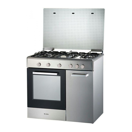
Summary of Contents for Elba N58740 Series
- Page 1 Mode d’emploi - Conseils pour l’installation GAS/ELECTRIC COOKERS CUISINIERES A GAZ/ELECTRIQUES MODELS / MODELES: • N58 .. 740 • N58 .. 742 ELBA QUALITY MADE IN ITALY H O M E A P P L I A N C E S Made in Italy...
- Page 2 English Instructions for the use - Installation advices Page 3 The manufacturer cannot be held re spon sible for possible inaccuracies due to printing or transcription errors in the present booklet. The manufacturer re serves the right to make all modifications to its products deemed necessary for manufacturer commercial reasons at any moment and without prior notice, without jeopardising the es sential functional and safety characteristics of the appliances.
- Page 3 Dear Customer, Thank you for having purchased and given your preference to our product. The safety precautions and recommendations reported below are for your own safety and that of others. They will also provide a means by which to make full use of the features offered by your appliance.
- Page 4 IMPORTANT INSTRUCTIONS AND ADVICE FOR THE USE OF ELECTRICAL APPLIANCES The use of any electrical appliance requires the compliance with some basic rules, namely: • do not touch the appliance with wet or damp hands (or feet); • do not use the appliance whilst in bare feet; •...
- Page 5 IMPORTANT SAFEGUARDS AND WARNING: • When correctly installed, your product meets all safety requirements RECOMMENDATIONS laid down for this type of product catego- After unpacking the appliance, check to ry. However special care should be taken ensure that it is not damaged and that the around the rear or the underneath of the oven door closes correctly.
-
Page 6: Cooking Hob
COOKING HOB Fig. 1.1 GAS BURNERS AND ELECTRIC HOTPLATES Auxiliary burner (A) 1,00 kW Rapid burner (R) 3,00 kW Semi-rapid burner (SR) 1,75 kW Electrical plate - Ø 145 mm 1000 W Electrical plate - Ø 180 mm 1500 W... -
Page 7: Control Panel
CONTROL PANEL Fig. 2.1 Only for model N58 .. 740 CONTROLS DESCRIPTION Rear right burner control knob Front right burner control knob Rear central electric plate control knob Front central electric plate control knob Front left burner control knob Rear left burner control knob Oven light / rotisserie control button Electric oven/grill control knob Gas burners electronic igniter control button... -
Page 8: Use Of Cooking Hob
USE OF COOKING HOB Each burner is controlled by a gas tap (fig. 3.1) assuring the opening and the closing of the gas supply. Make the knob symbols match with the in- dicator on the control panel to obtain: • symbol : off •... -
Page 9: Lighting The Burners
LIGHTING THE BURNERS CHOICE OF THE BURNER To ignite the burner, the following instruc- On the control panel, near every knob, the- tions are to be followed: re is a diagram that indicates which burner is controlled by that knob. Press in the corresponding knob and turn counter-clockwise (fig. - Page 10 PROPER USE OF THE ELECTRIC NORMAL HOTPLATES HOTPLATE (fig. 3.6) To switch on the normal hotplate, turn the When the pan comes to the boil, turn the knob (Fig. 3.5) onto the desired position; the numbers 1 to 6 indicate the working heat down to the level desired.
- Page 11 ELECTRIC HOTPLATE USAGE TABLE Position TYPE OF COOKING of switch Switched OFF For melting operations (butter, chocolate). To maintain food hot and to heat small quantities of liquid (sauces, eggs). To heat bigger quantities; to whip creams and sauces. (vegetables, fruits, soups). Slow boiling, i.e.: boiled meats, spaghetti, soups, continuations of steam,...
-
Page 12: General Features
NATURAL CONVECTION ELECTRIC OVEN ELECTRICAL THERMOSTAT The glass of the oven door reaches Turn on the oven or grill element by turning high temperatures during operation. the switch that is also provided with a ther- Keep children away. mostat to control the oven temperature. The cooker lid must be kept open On the knob (fig. - Page 13 USE OF THE GRILL WARNING: The door is hot, use the handle. Very important: the grill must always be During use the appliance becomes used with the oven door slightly open hot. Care should be taken to avoid and with shield “A” mounted (fig. 4.3). touching heating elements inside the Mount shield “A” which permits to protect oven.
-
Page 14: Oven Light
OVEN LIGHT ROTISSERIE The oven is equipped with a light that illu- The oven is equipped with a rotisserie for minates the oven to enable visually control- cooking on the spit using the grill. ling the food that is cooking. This device is made up of: The light is operated by the switch indica- •... - Page 15 60’ ALARM - only for model N58 .. 740 60’ ALARM (Fig. 5.1) The minute counter is a timed acoustic warning device which can be set for a ma- ximum of 60 minutes. The knob must be rotated clockwise as far as the 60 minute position and then set to the required time by rotating it anticlockwi- Fig.
-
Page 16: General Advice
ADVICE FOR THE CONSUMER GENERAL ADVICE ENAMELLED PARTS • Important: before any operation of All the enamelled parts must be cleaned cleaning and maintenance discon- with a sponge and soapy water or other nect the appliance from the electri- non-abrasive products. cal network. - Page 17 INSIDE OF OVEN BURNERS These parts can be removed and cleaned The oven should always be cleaned after with appropriate products. After cleaning, use when it has cooled down. the burners and their flame spreaders must The cavity should be cleaned using a mild be well dried and correctly replaced.
- Page 18 GLASS LID (models with glass lid) For cleaning purposes, the lid can be ea- Models with glass lid sily removed upwards once taken to the upright position. Should the hinges slip off, replace them in their housing being careful that: •...
- Page 19 Advice for the installer IMPORTANT • Cooker installation must only be carried out by QUALIFIED TECHNICIANS and in compliance with local safety standards. • The appliance must be installed in compliance with regulations in force in your country and in observation of the manufacturer’s instructions. •...
-
Page 20: Installation
INSTALLATION INSTALLATION The cookers afford class ‘1’ protection against overheating of surrounding surfaces. A space of at least 2 cm must be left between the cooker and any adjacent furniture, which must not exceed the height of the cooktop (fig. 6.1). If the cooker is installed adjacent to furniture which is higher than the gas hob cooktop, a gap of at least 30 cm must be left between the side of the cooker and the furniture. - Page 21 CHOOSING SUITABLE SURROUN- DINGS This appliance is not connected to a device to evacuate the combustion In the room chosen to accommodate the products. This must be installed and gas appliance, there must be an adequa- connected in conformity with the in- te natural draft to allow combustion of the stallation rules in force.
-
Page 22: Gas Section
GAS SECTION GAS CONNECTION Before installation, make sure that The connection must be executed by a the local distribution conditions qualified technician according to the re- (type of gas and its pressure) and the levant standards. adjustment of this appliance are com- The appliance is predisposed and cali- patible. The appliance adjustment brated to operate with the gas indicated... - Page 23 Gas connection for: Cat: I 3+ The fitting (fig. 8.3) is made up of: • 1 adapter “B” for G30/G31 • gasket “D” L.P.G. G30/G31 • Connect the cooker to the cylinder pressure regulator by a suitable rub- ber tube (inside diameter 6 mm). Make sure the tube is snugly fit at both ends and use a standard tube clamp (not supplied) to fasten it.
-
Page 24: Gas Cylinder Connection
GAS CYLINDER CONNECTION The connection between the hose con- nector on the cooker and the regulator of the gas cylinder must be made using a 60 cm long flexible hose conforming to applicable standards, and hose clamps. The connection hose must be inserted in the hose support (fig. -
Page 25: Replacement Of Burner Injectors
GAS MAINTENANCE REPLACEMENT OF BURNER INJECTORS If the injectors are not supplied they can be obtained from the “Service Centre”. Select the injectors to be replaced accor- ding to the “Table for the choice of the in- jectors”. To replace the injectors proceed as fol- lows: •... -
Page 26: Lubrication Of The Gas Taps
TABLE FOR THE CHOICE OF THE INJECTORS Cat: I 3+ G30 28-30 mbar Nominal Reduced G31 37 mbar BURNERS Power Power [kW] [kW] Ø injector [1/100 mm] Auxiliary (A) 1,00 0,30 Semi-rapid (SR) 1,75 0,45 Rapid (R) 3,00 0,75 AIR VENT NECESSARY FOR GAS COMBUSTION = (2 m /h x kW) BURNERS Air necessary for combustion [m... -
Page 27: Electrical Section
ELECTRICAL SECTION N.B. For connection to the mains, do IMPORTANT: The cooker must be in- not use adapters, reducers or bran- stalled in accordance with the manu- ching devices as they can cause facturer’s instructions. overheating and burning. Incorrect installation, for which the manufacturer accepts no responsibili- If the installation requires alterations to the ty, may cause damage to persons, ani- domestic electrical system, call an expert. - Page 28 ELECTRICAL FEEDER CABLE CONNECTION The operations must be executed by a qualified technician. To connect the supply cable: • Remove the screws securing the cover “A” on the rear of the cooker (fig. 9.1). • Feed the supply cable through the cable clamp “C” (fig. 9.1). The supply cable must be of a suitable size for the current requirements of the appliance;...
- Page 29 Cher Client, Vous venez d’acquérir une de nos cuisinières et nous vous remercions de votre choix. Celle-ci a été soigneusement conçue, fabriquée et testée pour votre plus grande satisfaction. Pour être à même de l’utiliser dans les meilleures conditions et pour obtenir ce que vous êtes en droit d’en attendre, nous vous conseillons de lire très attentivement cette NOTICE D’UTILISATION.
- Page 30 AVERTISSEMENTS ET CONSEILS IMPORTANTS POUR L’UTILISATION DES APPAREILS ELECTRIQUES L’utilisation d’un appareil électrique comporte l’observance de certaines précautions fondamentales. En particulier: • éviter de toucher l’appareil les mains ou pieds mouillés; • éviter l’utilisation de l’appareil les pieds nus; • éviter l’utilisation de l’appareil aux enfants ou aux incapables, sans surveillance.
- Page 31 PRECAUTIONS ET CONSEILS • AVERTISSEMENT Lorsqu’il est correcte- ment installé, votre appareil répond à to- IMPORTANTS utes les exigences de sécurité prescrites Après avoir éliminé l’emballage, vérifier pour ce type de produit. Toutefois, vous que l’appareil est en bon état. En cas de devez porter une attention particulière à...
- Page 32 TABLE DE TRAVAIL Fig. 1.1 BRULEURS A GAZ ET PLAQUES ELECTRIQUES Brûleur auxiliaire (A) 1,00 kW Brûleur rapide (R) 3,00 kW Brûleur semirapide (SR) 1,75 kW Foyer normale Ø 145 mm 1000 W Foyer normale Ø 180 mm 1500 W...
-
Page 33: Description Des Commandes
TABLEAU DE BORD Fig. 2.1 Seulement pour le modèle N58 .. 740 DESCRIPTION DES COMMANDES Manette commande brûleur arrière droite Manette commande brûleur avant droite Manette commande foyer arrière central Manette commande foyer avant central Manette commande brûleur avant gauche Manette commande brûleur arrière gauche Bouton commande éclairage du four/tournebroche Manette commande four / grilloir électrique... - Page 34 TABLE DE TRAVAIL - MODE D’EMPLOI UTILISATION DES BRULEURS L’arrivée du gaz dans les brûleurs est com- mandée par le bouton qui commande les robinets de sûreté. En faisant coïncider les symboles de la ma- nette (fig. 3.1) avec le repère marqué sur le tableau de bord, nous aurons: robinet fermé...
- Page 35 ALLUMAGE DES BRULEURS CHOIX DU BRULEUR Pour allumer le brûleur, vous devez La position des brûleurs est marquée sur le placer la manette (Fig. 3.2) corre- tableau de bord. Le symbole de couleur ou spondant au brûleur en question sur graphisme différent indique le brûleur que la position symbole “grande”...
- Page 36 EMPLOI CORRECT DES PLAQUES PLAQUE NORMALE ELECTRIQUES (fig. 3.5) La mise en marche de la plaque normale Lorsqu’on utilise la plaque électrique, il se fait en tournant la manette (fig. 3.4) sur la position retenue. faut: • éviter à tout prix de la faire fonctionner Les allures de 1 à...
- Page 37 TABLEAU POUR L’UTILISATION DES PLAQUES ELECTRIQUES Position TYPE DE CUISSON manette Eteint Pour fondre (beurre, chocolat). Pour maintenir les aliments au chaud ou chauffer des li- quides en petite quantité. Pour chauffer des liquides en quantités plus importantes; réduction de sauces ou crè- mes.
-
Page 38: Caracteristiques Generales
FOUR ELECTRIQUE A CONVECTION NATURELLE THERMOSTAT ELECTRIQUE Le verre de la porte du four chauffe pen- La mise en marche des résistances, soit du four, dant l’utilisation. soit du grill, se réalise en tournant le commutateur Eloigner les jeunes enfants. correspondant au thermostat qui règle la tem- Le couvercle de la cuisinière doit être pérature du four. - Page 39 UTILISATION DU GRILLOIR ATTENTION : Très important: à effectuer toujours à La porte est chaude, utiliser la poi- porte entr’ouverte et avec le déflecteur gnée. “A” montée (Fig. 4.2). Pendant l’utilisation l’appareil devient chaud. Faire de l’attention à ne pas Mettre en place l’écran “A”...
-
Page 40: Utilisation Du Tournebroche
ECLAIRAGE TOURNEBROCHE L’appareil est équipé d’une lampe pour Celui-ci sert à cuire les mets à la broche en l’éclairage du four, permettant un contrôle utilisant le grill. visuel des mets, porte fermée. Cet accessoire se compose de: Cette lampe est commandée par l’interrup- •... - Page 41 MINUTEUR SONORE seulement pour le modèle N58 .. 740 MINUTEUR SONORE 60’ (Fig. 5.1) La minuteur est un avertisseur acoustique à temps qui peut être réglé pour une pério- de maximum de 60 minutes. La manette de réglage (fig. 5.1) doit être tournée dans le sens des aiguilles d’un montre jusqu’à...
-
Page 42: Nettoyage Et Entretien
NETTOYAGE ET ENTRETIEN CONSEILS GENERAUX PARTIES EMAILLEES • Important: avant toute opération Toutes les parties émaillées doivent être d’entretien ou de maintenance, dé- lavées avec une éponge, à l’eau savon- connectez l’appareil en le débran- neuse, ou avec d’autres produits qui ne chant ou bien en agissant sur l’in- soient pas abrasifs. - Page 43 INTERIEUR DU FOUR BULEURS ET GRILLES Le four doit être nettoyé chaque fois après Ces pièces peuvent être enlevées et la- utilisation, lorsqu il est tiède. vées avec des produits appropriés. La cavité doit être nettoyée avec une solu- Après le nettoyage, les brûleurs et leurs tion de détergent doux et de l’eau tiède.
- Page 44 COUVERCLE EN VERRE (seulement Modèles avec couvercle en verre pour les modèles avec couvercle en verre) Ouvrir complètement le couvercle, sou- lever de côté gauche et puis, le déplacer légèrement vers la gauche. Si les charnières se dégagent, il faut les re- mettre dans leurs logements en veillant à: Ne pas fermer le couvercle si •...
- Page 45 Conseils à l’installateur IMPORTANT • L’installation de la cuisinière doit être réalisée par des TECHNICIENS QUALIFIES. • L’installation gaz et électrique doivent être exclusivement effectuées conformément aux prescriptions locales en vigueur et aux instructions du fabricant. • Toutes les interventions doivent être effectuées lorsque l’appareil est débranché. •...
- Page 46 INSTALLATION INSTALLATION Les cuisinières sont de classe “1” en ce qui concerne Ia protection contre la surchauffe des surfaces environnantes. L’installation doit s’effectuer en gardant une distance de 2 cm par rapport aux parois latéra- les des meubles qui ne doivent pas dépasser la hauteur de la table de cuisson. (fig. 7.1). Si la cuisinière est installée près d’un meuble qui est plus haut que le dessus de la table de travail de la cuisinière, un espace d’au moins 30 cm doit être aménagé...
-
Page 47: Local D'installation
LOCAL D’INSTALLATION L’installateur doit se rapporter aux La pièce dans laquelle l’appareil à gaz est normes locales en vigueur en ce qui installé doit avoir un apport d’air nécessai- concerne la ventilation et l’évacuation re à la combustion du gaz. des produits de combustion. - Page 48 PARTIE GAZ RACCORDEMENT AU GAZ Avant l’installation, s’assurer que le Le raccordement doit être effectué par réseau de distribution local (type de un technicien spécialisé conformément gaz et pression) et les caractéristi- aux normes locales en vigueur. ques de l’appareil sont compatibles. L’appareil est fourni prête à fonctionner Les caractéristiques sont indiquées suivant le gaz indiqué...
- Page 49 Raccordement gaz pour: Cat: I 3+ Le groupe raccordement (fig. 8.3) se com- pose de: • 1 embout-réduction “B” • rondelle d’étanchéite “D” G30/G31 (butane/propane) • Brancher la cuisinière au détendeur de la bouteille avec un tuyau convenable en caoutchouc au diamètre intérieur de 6 mm.
- Page 50 PORTE-BOUTEILLE Le branchement entre le support de tube et le régulateur de pression de la bouteille de gaz doit être effectué par le blais d’un tube flexible, répondant aux normes en vigueur, d’une longueur de 75 cm, avec les collier serre-tête correspondants. Ce tube doit être inséré...
- Page 51 ENTRETIEN PARTIE GAZ REMPLACEMENT DES INJECTEURS DES BRULEURS DE LA TABLE Au cas où ils ne seraient pas fournis, on peut les trouver auprès des Services Après-Vente. Consulter le “Tableau des injecteurs” pour ce qui concerne le diamètre des injecteurs à...
- Page 52 TABLEAU DES INJECTEURS Cat: I 3+ G30 28-30 mbar Débit Débit G31 37 mbar BRULEURS nominal réduit [kW] [kW] Ø injecteur [1/100 mm] Auxiliaire (A) 1,00 0,30 Semi-rapide (SR) 1,75 0,45 Rapide (R) 3,00 0,75 APPORT D’AIR NÉCESSAIRE À LA COMBUSTION DU GAZ = (2 m /h x kW) BURNERS Apport d’air nécessaire [m...
-
Page 53: Partie Electrique
PARTIE ELECTRIQUE N.B. Ne pas utiliser d’adaptateurs, de IMPORTANT: L’installation doit suivre réducteurs ou de dérivateurs lors du les instructions du constructeur. branchement au réseau, car ils peuvent Une installation erronée peut causer provoquer des surchauffements ou des des dommages aux personnes, ani- brûlures. maux ou choses. Si l’installation électrique doit être modifiée Le constructeur ne peut pas être con- pour le branchement, faire appel à... - Page 54 BRANCHEMENT DU CABLE D’ALIMENTATION Les opérations doivent être exécutées par un technicien qualifié. Pour le branchement du câble d’alimentation: • Dévissez les vis de fixation de la protection “A” située derrière la cuisinière (fig. 9.1). • Placez le câble d’alimentation à travers du collier de serrage “C”. Le câble d’alimenta- tion doit présenter une dimension adaptée aux caractéristiques électriques de l’appa- reil.
- Page 56 The manufacturer cannot be held responsible for possible inaccuracies due to printing or transcrip- tion errors in the present booklet. The manufacturer reserves the right to make all modifications to its products deemed necessary for manufacture or commercial reasons at any moment and without prior notice, without jeopardising the essential functional and safety characteristics of the appliances.
Need help?
Do you have a question about the N58740 Series and is the answer not in the manual?
Questions and answers