
Related Manuals for Elba S 61 X 631 F


Summary of Contents for Elba S 61 X 631 F
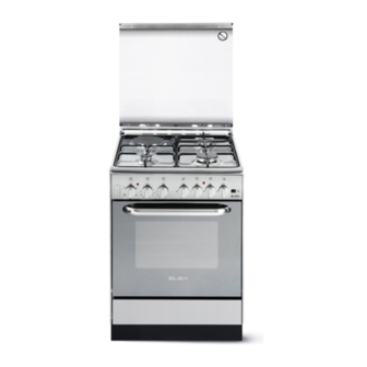
- Page 1 Instructions for the use - Installation advices DUAL FUEL COOKERS ELBA QUALITY MADE IN ITALY Made in Italy...
- Page 3 Dear Customer, Thank you for having purchased and given your preference to our product. The safety precautions and recommendations reported below are for your own safety and that of others. They will also provide a means by which to make full use of the features offered by your appliance.
-
Page 4: Important Safety Precautions And Recommendations
IMPORTANT SAFETY PRECAUTIONS AND RECOMMENDATIONS IMPORTANT: This appliance is designed and manufactured solely for the cooking of domestic (household) food and is not suitable for any non domestic application and therefore should not be used in a commercial environment. The appliance guarantee will be void if the appliance is used within a non domestic environment i.e. - Page 5 • Do not use a steam cleaner because the moisture can get into the appliance thus make it unsafe. • Do not touch the appliance with wet or damp hands (or feet). • Do not use the appliance whilst in barefoot. • If you should decide not to use this appliance any longer (or decide to substitute another model), before disposing of it, it is recommended that it be made inoperative in an appropriate manner in accordance to...
- Page 6 • WARNING: Danger of fire: do not store items on the cooking surfaces. • WARNING: If the hob is cracked or otherwise damaged by falling objects etc., disconnect the appliance from the electrical power supply to avoid the possibility of electric shock and call Customer Service. • WARNING: When correctly installed, your product meets all safety requirements laid down for this type of product category.
-
Page 7: Cooking Hob
COOKING HOB Fig. 1.1 GAS BURNERS / ELECTRIC HOTPLATE Auxiliary burner (A) 1,00 kW Semi-rapid burner (SR) 1,75 kW Rapid burner (R) 3,00 kW Electrical plate - Ø 145 mm (Normal) 1000 W (230V) - 915 W (220V) CAUTION: Gas appliances produce heat and humidity in the environment in which they are installed. Ensure that the cooking area is well ventilated by opening the natural ventilation grilles or by installing an extractor hood connected to an outlet duct. -
Page 8: Control Panel
CONTROL PANEL Fig. 2.1 M A D E I N I T A L Y CONTROLS DESCRIPTION Front right burner control knob Rear right burner control knob Rear left electrical plate control knob Front left burner control knob 60’ alarm Electric oven thermostat control knob Electric oven selector control knob Electronic ignition pushbutton... -
Page 9: Use Of The Hob Burners
USE OF THE HOB BURNERS GAS BURNERS Gas flow to the burners is adjusted by turning the knobs (illustrated in fig. 3.1). Turning the knob, so that the indicator line points to the symbols printed on the panel, achieves the following functions: - symbol closed valve maximum... -
Page 10: Lighting The Burners
LIGHTING THE BURNERS CHOICE OF THE BURNER ignite burner, following On the control panel, near every knob instructions are to be followed: there is a diagram that indicates which burner is controlled by that knob. Press in the corresponding knob and The suitable burner must be chosen turn counter-clockwise (fig. - Page 11 CORRECT USE OF THE RAPID BURNER (figs. 3.5a - 3.5b) This special grille for woks should be placed over the pan-rest for the rapid burner. Warning: • Using woks without this special grille may cause the burner to malfunction. • Do not use the grille for ordinary, flat-bottomed saucepans.
-
Page 12: Electric Hotplate
PROPER USE OF THE ELECTRIC ELECTRIC HOTPLATE HOTPLATE (fig. 3.6) When the pan comes to the boil, turn the heat down to the level desired. Remember that the hotplate will continue Never cook the food directly on to produce heat for about five minutes after the hotplate, but in special pans or it has been turned off. - Page 13 ELECTRIC HOTPLATE USAGE TABLE Position TYPE OF COOKING of switch Switched OFF For melting operations (butter, chocolate). To maintain food hot and to heat small quantities of liquid (sauces, eggs). To heat bigger quantities; to whip creams and sauces. (vegetables, fruits, soups). Slow boiling, i.e.: boiled meats, spaghetti, soups, continuations of steam,...
-
Page 14: Operating Principles
PLURIFUNCTION OVEN OPERATING PRINCIPLES Attention: The oven door becomes Heating and cooking in the plurifunction very hot during operation. oven are obtained: Keep children away. a. by natural convection The cooker lid must be kept open when The heat is produced by the upper and the oven or the grill is in use. -
Page 15: Thermostat Knob
Fig. 4.1 Fig. 4.2 THERMOSTAT KNOB (fig. 4.2) To turn on the heating elements of the oven, set the function selector knob on the desired program and the thermostat knob onto the desired temperature. To set the temperature, it is necessary to make the knob indicator meet the chosen number. The elements will turn ON or OFF automatically according to the energy need which is determined by the thermostat. -
Page 16: Defrosting Frozen Foods
CONVECTION COOKING WITH VENTILATION The upper and lower heating elements come on and the fan. The heat coming from above and below is diffused by forced convection. The temperature must be set to between 50° and 250°C via the thermostat knob. Recommended for: Voluminous dishes and large quantities which require the same degree of cooking both inside and out, for example rolled roasts, turkey, roast legs, cakes etc. -
Page 17: Cooking Advices
COOKING ADVICES COOKING ADVICE STERILIZATION GRILLING AND “AU GRATIN” Sterilization of foods to be conserved, in Grilling may be done without the roasting full and hermetically sealed jars, is done in jack on position of the switch, because the following way: the hot air completely envelops the food that is to be cooked. -
Page 18: Oven Cooking
COOKING DIFFERENT DISHES AT OVEN COOKING THE SAME TIME To cook, before introducing the food, preheat the oven to the desired temperature. With the function selector in position When the oven has reached the desired the ventilated oven allows you to cook temperature, introduce the food, control different types of food at the same time. -
Page 19: Minute Counter
60’ ALARM MINUTE COUNTER The minute counter is a timed acoustic warning device which can be set for a maximum of 60 minutes. The knob (fig. 5.1) must be rotated clockwise as far as the 60 minute position and then set to the required time by rotating it anticlockwise. -
Page 20: Cleaning And Maintenance
CLEANING AND MAINTENANCE GENERAL ADVICE ENAMELLED PARTS • Before you begin cleaning, you All the enamelled parts must be cleaned must ensure that the appliance is with a sponge and soapy water or other disconnected from the electrical non-abrasive products. power supply. -
Page 21: Replacing The Oven Light Bulb
HOT PLATE Models with glass lid Foods burned on the hot plates must always be cleaned dry. Do not use water to avoid the forming of rust. After its use, pour a bit of oil onto the warm plate and rub with a cloth. - Page 22 GAS TAPS CORRECT REPLACEMENT OF THE BURNERS Periodic lubrication of the gas taps must be carried out by specialist personnel only. It is very important to check that the burner In the event of operating faults in the gas flame distributor “F” and the cap “C” has taps, call the Service Department.
- Page 23 INSIDE OF OVEN The oven should always be cleaned after use when it has cooled down. The cavity should be cleaned using a mild detergent solution and warm water. Suitable proprietary chemical cleaners may be used after first consulting with the manufacturers recommendations and testing a small sample of the oven cavity.
-
Page 24: Removing The Oven Door
REMOVING THE OVEN DOOR The oven door can easily be removed as follows: • Open the door to the full extent (fig. 6.8a). • Open the lever “A” completely on the left and right hinges (fig. 6.8b). • Hold the door as shown in fig. 6.8. •... -
Page 25: Installation
Advice for the installer IMPORTANT • Cooker installation must only be carried out by QUALIFIED TECHNICIANS and in compliance with local safety standards. Failure to install the appliance correctly could invalidate any manufacturer’s warranty. • The appliance must be installed in compliance with regulations in force in your country and in observation of the manufacturer’s instructions. - Page 26 ■ Class 1 (fig. 7.2a) connection made using rubber hose which must be visible and easily inspected or using rigid or flexible metal pipe. A space of at least 2 cm must be left between the cooker and any adjacent furniture, which must not exceed the height of the cooktop.
-
Page 27: Ventilation Requirements
VENTILATION REQUIREMENTS The appliance must be installed in compliance with applicable local regulations concerning ventilation and the evacuation of exhaust gases. Intensive and prolonged use may require extra ventilation, e.g. opening a window, or more efficient ventilation increasing the mechanical suction power if this is fitted. CHOOSING SUITABLE SURROUNDINGS The room where the gas appliance is to be installed must have a natural flow of air so that the gas can burn (in compliance with applicable local regulations). -
Page 28: Gas Section
GAS SECTION GAS INSTALLATION REQUIREMENTS Important ! • The walls adjacent to the cooker must be of heat-resistant material. Before installation, make sure that the local distribution conditions (gas type and • pressure) and the adjustment of this appliance are compatible. The appliance adjustment conditions are given on the plate or the label. - Page 29 GAS CONNECTION WITH A RUBBER HOSE Important! A rubber hose connection shall only be made if permitted by the applicable local regulations. The gas connection is made up of: • the terminal fitting of the inlet pipe (right-hand or left-hand); •...
- Page 30 Gas connection with rubber hose holder Note: if not already fitted on the inlet pipe, the hose holder is supplied with the product in a separate kit; if not supplied with the appliance it can be purchased by contacting the After-Sales Service. (Important: to be used ONLY IF PERMITTED by the local applicable regulations) Inlet pipe Manifold...
- Page 31 • the flexiple pipe does not exceed 2000 mm in length (or refer to applicable local regulations) and does not come into contact with sharp edges, corners or moving parts. Use a single flexible pipe only; never connect the cooker with more than one flexible pipe.
-
Page 32: Lubrication Of The Gas Taps
GAS MAINTENANCE TABLE FOR THE CHOICE OF THE INJECTORS - Cat. G30 (28-30 mbar) Nominal Reduced G31 (37 mbar) BURNERS power power [kW] [kW] Ø injector [1/100 mm] Auxiliary (A) 1,00 0,30 Semi-rapid (SR) 1,75 0,45 Rapid (R) 3,00 0,75 AIR VENT NECESSARY FOR GAS COMBUSTION = (2 m /h x kW) BURNERS... -
Page 33: Adjusting Of The Minimum Of The Top Burners
REPLACEMENT INJECTORS If the injectors are not supplied they can be obtained from the “Service Centre”. Select the injectors to be replaced according to the “Table for the choice of the injectors”. nozzle diameters, expressed hundredths of a millimetre, are marked on the body of each injector. -
Page 34: Electrical Section
ELECTRICAL SECTION N.B. For connection to the mains, do IMPORTANT: The cooker must be not use adapters, reducers or branching installed accordance with devices as they can cause overheating manufacturer’s instructions. and burning. Incorrect installation, which If the installation requires alterations to the manufacturer accepts domestic electrical system or if the socket... -
Page 35: Connection Of The Power Supply Cable
CONNECTION OF THE POWER SUPPLY CABLE WARNING: If the power supply cable is damaged, it must be replaced only by an authorised service agent in order to avoid a hazard. • Unhook the terminal board cover by inserting a screwdriver into the two hooks “A” (fig. 9.1). •... - Page 36 The manufacturer reserves the right to make all modifications to its products deemed necessary for manufacturer commercial reasons at any moment and without prior notice, without jeopardising the essential functional and safety characteristics of the appliances. www.elba-cookers.it Made in Italy Cod. 1104885 - ß3...
Need help?
Do you have a question about the S 61 X 631 F and is the answer not in the manual?
Questions and answers