
Subscribe to Our Youtube Channel
Related Manuals for Elba E K55 X 220


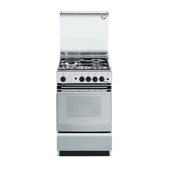
Summary of Contents for Elba E K55 X 220
- Page 1 Instructions for the use - Installation advices COOKERS ELBA QUALITY MADE IN ITALY Made in Italy...
- Page 3 Dear Customer, Thank you for having purchased and given your preference to our product. The safety precautions and recommendations reported below are for your own safety and that of others. They will also provide a means by which to make full use of the features offered by your appliance.
-
Page 4: Important Safety Precautions And Recommendations
IMPORTANT SAFETY PRECAUTIONS AND RECOMMENDATIONS IMPORTANT: This appliance is designed and manufactured solely for the cooking of domestic (household) food and is not suitable for any non domestic application and therefore should not be used in a commercial environment. The appliance guarantee will be void if the appliance is used within a non domestic environment i.e. - Page 5 • WARNING: Ensure that the appliance is switched off before replacing the oven lamp to avoid the possibility of electric shock. • Do not use a steam cleaner because the moisture can get into the appliance thus make it unsafe. • Do not touch the appliance with wet or damp hands (or feet).
- Page 6 To avoid burns and scalds, young children should be kept – away. • Make sure that electrical cables connecting other appliances in the proximity of the cooker cannot come into contact with the hob or become entrapped in the oven door. • WARNING: Unattended cooking on a hob with fat or oil can be dangerous and may result in fire.
- Page 7 • FIRE RISK! Do not store flammable material in the oven or in the storage compartment. • Always use oven gloves when removing the shelves and food trays from the oven whilst hot. • Do not hang towels, dishcloths or other items on the appliance or its handle –...
- Page 8 COOKING HOBS Fig. 1.1 Models: E K55 X 220 • • E 5540 FG2 BK Fig. 1.2 Models: E 5531 FG2 BK • • E K55 X 320 GAS BURNERS AND ELECTRIC HOTPLATES 1. Auxiliary burner (A) 1,00 kW 2. Rapid burner (R) 3,00 kW 3.
-
Page 9: Control Panels
CONTROL PANELS Models: • E K55 X 220 Fig. 2.1 • E 5540 FG2 BK Models: E 5531 FG2 BK • • E K55 X 320 Fig. 2.2 CONTROLS DESCRIPTION Rear right burner control knob Front right burner control knob... -
Page 10: Use Of Cooking Hob
USE OF COOKING HOB Each burner is controlled by a gas tap (fig. 3.1) assuring the opening and the closing of the gas supply. Make the knob symbols match with the indicator on the control panel to obtain: • symbol : off •... -
Page 11: Lighting The Burners
LIGHTING THE BURNERS CHOICE OF THE BURNER ignite burner, following On the control panel, near every knob, instructions are to be followed: there is a diagram that indicates which burner is controlled by that knob. Press in the corresponding knob and turn counter-clockwise (fig. - Page 12 CORRECT USE OF RAPID BURNER (Some models only) The flat-bottomed pans are to be placed directly onto the pan-support. When using a WOK you need to place the supplied stand in the burner to avoid any faulty operation of the rapid burner (fig. 3.5a - 3.5b). IMPORTANT: The special grille for wok pans (fig.
- Page 13 ONLY FOR MODELS WITH ELECTRIC HOTPLATE PROPER USE OF THE ELECTRIC RAPID HOTPLATE HOTPLATE (fig. 3.7) To switch on the rapid hotplate, turn the When the pan comes to the boil, turn the knob (fig. 3.6) onto the desired position; heat down to the level desired.
- Page 14 ELECTRIC HOTPLATE USAGE TABLE Position TYPE OF COOKING of switch Switched OFF For melting operations (butter, chocolate). To maintain food hot and to heat small quantities of liquid (sauces, eggs). To heat bigger quantities; to whip creams and sauces. (vegetables, fruits, soups). Slow boiling, i.e.: boiled meats, spaghetti, soups, continuations of steam,...
-
Page 15: General Features
USE OF THE GAS OVEN OVEN BURNER The glass on the oven door reaches It carries out normal “oven cooking”. high temperatures during operation. The gas flow to the burner is regulated by Keep children away. a thermostat which allow to maintain the The cooker lid must be kept open when oven temperature constant. - Page 16 IGNITION OF THE OVEN BURNER Models E K55..320, E K55..220 Models 5540FG2-.., ATTENTION: Never turn thermostat before approaching a flame 5531FG2-.. to the hole “A” of the floor. WARNING: Risk of explosion! The ATTENTION: Never turn oven door must be open during this thermostat before approaching a flame operation. to the hole “A” of the floor. WARNING: Risk of explosion! The To ignite the oven burner: oven door must be open during this operation.
-
Page 17: Oven Cooking
Models E K55..320, E K55..220 OVEN COOKING To cook, before introducing the food, preheat If the flame extinguishes for any reason, the oven to the desired temperature. the safety valve will automatically shut off When the oven has reached the desired the gas supply to the burner. - Page 18 IGNITION OF THE GRILL BURNER IGNITION OF THE GRILL BURNER (Models E K55..220, E K55..320) (Models 5540FG2-.., 5531FG2-..) To ignite the grill burner: Open the oven door to the full extent. WARNING: Risk of explosion! The ATTENTION: Never turn oven door must be open during this thermostat before approaching a flame operation.
-
Page 19: Use Of The Grill
USE OF THE GRILL ROTISSERIE Very important: the grill must always be The oven is equipped with a rotisserie for used with the oven door slightly open cooking on the spit using the grill. and with shield “A” mounted (fig. 4.9) This device is made up of: The oven door becomes very hot during •... - Page 20 ADVICE FOR THE CONSUMER GLASS LID (models with glass lid) Models with glass lid For cleaning purposes, the lid can be easily removed upwards once taken to the upright position. Should the hinges slip off, replace them in their housing being careful that: •...
-
Page 21: General Advice
GENERAL ADVICE ENAMELLED PARTS • Important: before any operation All the enamelled parts must be cleaned cleaning maintenance with a sponge and soapy water or other disconnect the appliance from the non-abrasive products. electrical network (only for models Dry preferably with a microfibre or soft with electrical components). - Page 22 BURNERS CORRECT REPLACEMENT OF THE BURNERS They can be removed and washed with soapy water only. It is very important to check that the burner They will remain always perfect if cleaned flame distributor “F” and the cap “C” has with products used for silverware.
- Page 23 FITTING THE OVEN SHELF Security block • The oven shelf is provided with a security block to prevent accidental extraction. must inserted operating as per figure 5.4. • To pull it out operate in the inverse order. OVEN DOOR (Only for models EK 55 ..
-
Page 24: Important Warning
REPLACING OVEN LAMP REPLACING OVEN LAMP (MODELS WITH INCANDESCENT (MODELS WITH HALOGEN LAMP) LAMP) (Only for the models EK (Only for the models EK 55 .. 220, EK 55 .. 220, EK 55 .. 320) 55 .. 320) WARNING: Ensure the appliance is WARNING: Ensure the appliance is switched off and disconnected from the switched off and disconnected from the... -
Page 25: Removing The Oven Door
REMOVING THE OVEN DOOR The oven door can easily be removed as follows: • Open the door to the full extent (fig. 5.8a). • Open the lever “A” completely on the left and right hinges (fig. 5.8b). • Hold the door as shown in fig. 5.8. •... - Page 26 Advice for the installer IMPORTANT • Cooker installation must only be carried out by QUALIFIED TECHNICIANS and in compliance with local safety standards. Failure to comply with this condition will render the guarantee invalid. • The appliance must be installed in compliance with regulations in force in your country and in observation of the manufacturer’s instructions.
-
Page 27: Installation
INSTALLATION The cookers afford class ‘1’ protection against overheating of surrounding surfaces. The installation conditions, concerning protection against overheating of the surfaces adjacent to the cooker, must conform to fig. 6.1 and 6.2. The appliance must be kept no less than 300 mm away from any side wall which exceeds the height of the hob surface (fig. -
Page 28: Ventilation Requirements
VENTILATION REQUIREMENTS The appliance must be installed in compliance with applicable local regulations concerning ventilation and the evacuation of exhaust gases. Intensive and prolonged use may require extra ventilation, e.g. opening a window, or more efficient ventilation increasing the mechanical suction power if this is fitted. CHOOSING SUITABLE SURROUNDINGS The room where the gas appliance is to be installed must have a natural flow of air so that the gas can burn (in compliance with applicable local regulations). -
Page 29: Gas Section
GAS SECTION GAS INSTALLATION REQUIREMENTS Important ! The walls adjacent to the cooker must be of heat-resistant material. • • Before installation, make sure that the local distribution conditions (gas type and pressure) and the adjustment of this appliance are compatible. The appliance adjustment conditions are given on the plate or the label. - Page 30 GAS CONNECTION WITH A RUBBER HOSE Imporant! A rubber hose connection shall only be made if permitted by the applicable local regulations. The gas connection is made up of: • the terminal fitting of the inlet pipe; • sealing washer; •...
- Page 31 Gas connection with rubber hose holder Note: if not already fitted on the inlet pipe, the hose holder is supplied with the product in a separate kit (Important: to be used ONLY IF PERMITTED by the local applicable regulations) Inlet pipe Manifold male 1/2”...
- Page 32 • the flexiple pipe does not exceed 2000 mm in length (or refer to applicable local regulations) and does not come into contact with sharp edges, corners or moving parts. Use a single flexible pipe only; never connect the cooker with more than one flexible pipe.
-
Page 33: Lubrication Of The Gas Taps
GAS MAINTENANCE TABLE FOR THE CHOICE OF THE INJECTORS - Cat: G30 28-30 mbar Nominal Reduced G31 37 mbar BURNERS Power Power [kW] [kW] Ø injector Ring opening [1/100 mm] [mm] Auxiliary (A) 1,00 0,30 Semi-rapid (SR) 1,75 0,45 Rapid (R) 3,00 0,75 Oven... -
Page 34: Adjusting Of The Minimum Of The Top Burners
REPLACEMENT INJECTORS OF THE BURNERS The injectors can be obtained from the “Service Centre”. Select the injectors to be replaced according to the “Table for the choice of the injectors”. nozzle diameters, expressed hundredths of a millimetre, are marked on the body of each injector. -
Page 35: Oven Burner
OPERATIONS TO BE EXECUTED FOR THE REPLACEMENT OF THE INJECTORS OF THE OVEN AND GRILL BURNERS Select the injectors to be replaced according to the “Table for the choice of the injectors”. nozzle diameters, expressed hundredths of a millimetre, are marked on the body of each injector. -
Page 36: Adjustment Of The Oven Burner Minimum
ADJUSTMENT OF THE OVEN BURNER MINIMUM This needs to be done only for the oven burner (the grill is a fixed capacity) by acting on the thermostat. Considering that in the minimum position the flame must have a length of about 4 mm and must remain lit even with a brusque passage from the maximum position to that of minimum. -
Page 37: Electrical Section
ELECTRICAL SECTION N.B. For connection to the mains, do IMPORTANT: The cooker must be not use adapters, reducers or branching installed accordance with devices as they can cause overheating manufacturer’s instructions. and burning. Incorrect installation, which manufacturer accepts If the installation requires alterations to the responsibility, may cause damage to domestic electrical system or if the socket persons, animals and things. -
Page 38: Feeder Cable Section
ELECTRICAL FEEDER CABLE CONNECTION WARNING: If the power supply cable is damaged, it must be replaced only by an authorised service agent in order to avoid a hazard. To connect the supply cable: • Remove the screws securing the cover “A” on the rear of the cooker (fig. 8.1). •... - Page 40 The manufacturer reserves the right to make all modifications to its products deemed necessary for manufacturer commercial reasons at any moment and without prior notice, without jeopardising the essential functional and safety characteristics of the appliances. www.elba-cookers.it Made in Italy Cod. 1105158 - ß0...
Need help?
Do you have a question about the E K55 X 220 and is the answer not in the manual?
Questions and answers