
Related Manuals for Elba PX 96 990 AZ


Summary of Contents for Elba PX 96 990 AZ
- Page 1 Instructions for the use - Installation advices GAS COOKERS ELBA QUALITY MADE IN ITALY H O M E A P P L I A N C E S Made in Italy...
- Page 2 Dear Customer, Thank you for having purchased and given your preference to our product. The safety precautions and recommendations reported below are for your own safety and that of others. They will also provide a means by which to make full use of the fea- tures offered by your appliance.
- Page 3 IMPORTANT INSTRUCTIONS AND ADVICE FOR THE USE OF ELECTRICAL APPLIANCES The use of any electrical appliance requires the compliance with some basic rules, namely: – do not touch the appliance with wet or damp hands (or feet) – do not use the appliance whilst in bare feet –...
- Page 4 IMPORTANT SAFEGUARDS WARNING AND RECOMMENDATIONS When correctly installed, your product meets all safety requirements laid down for this type of product category. After unpacking the appliance, check to However special care should be taken ensure that it is not damaged and that around the rear or the underneath of the oven door closes correctly.
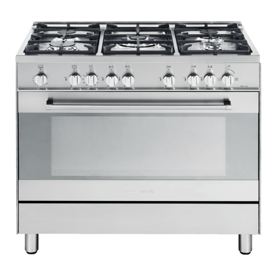
- Page 5 1 - COOKING HOB Mod. PX 96 990 AZ Fig. 1.1 CAUTION: Gas appliances produce heat and humidity in the environ- ment in which they are installed. Ensure that the cooking area is well ventilated by opening the natural ventilation grilles or by installing an extractor hood connected to an outlet duct.
- Page 6 2 - CONTROL PANEL Mod. PX 96 990 AZ Fig. 2.1 CONTROL PANEL - Controls description Gas oven thermostat control knob Gas grill control knob 60’ alarm knob Front left burner control knob Rear left burner control knob Central burner control knob...
- Page 7 3 - USE OF COOKING HOB GAS BURNERS Each burner is controlled by a gas tap assuring the opening and the closing of the gas supply. Turning the knob so that the indicator line points to the symbols printed on the panel achieves the following functions: –...
- Page 8 LIGHTING GAS BURNERS FITTED To ignite the burner, the following instructions are to be followed: 1) Press in the corresponding knob and turn counter-clockwise (fig. 3.2) to the full flame position marked by the symbol (fig. 3.1) and hold the knob in until the flame has been lit.
- Page 9 CHOICE OF THE BURNER It is important that the diameter of the pot be suitable to the potentiality of the On the control panel, near every knob, burner so as not to compromise the there is a diagram that indicates which high output of the burners and therefore burner is controlled by that knob.
- Page 10 4 - USE OF THE GAS OVEN THERMOSTAT Attention: the oven door becomes very hot during operation. The numbers 1 to 10 printed on the Keep children away. control panel (fig. 4.1) indicate the increasing oven temperature value (see table 4.2). To regulate the temperature, turn the GENERAL FEATURES knob so that the indicator line points to...
- Page 11 IGNITION OF THE OVEN BURNER 4) Wait about 10/15 seconds after the burner lighting before releasing the ATTENTION: Never turn the control knob (time of priming of the valve). knob before opening the oven door. 5) Close the oven door slowly and To ignite the oven burner: adjust the burner according to the power required.
- Page 12 OVEN COOKING COOKING EXAMPLES For efficient oven preheating, we rec- Temperatures are approximate as they ommend that grill trays and racks are vary depending on the quality and removed from the oven and replaced amount of food. after about 15 minutes. Remember to use ovenproof dishes and to adjust the oven temperature during Before introducing the food, preheat the...
- Page 13 GRILL BURNER IGNITION OF THE GRILL BURNER The grill is controlled by a gas tap ATTENTION: Never turn the control assuring the opening and the closing of knob before opening the oven door. the gas supply. To ignite the grill burner: Turning the knob (fig.
- Page 14 USE OF THE GRILL HOW TO OPERATE THE OVEN AND GRILL TOGETHER Turn on the grill as indicated in the previ- You can operate the oven and grill ous paragraph and leave to warm up for together following these instructions: approximately 5 minutes with the door Remove the tray and light the oven closed.
- Page 15 ROTISSERIE This device is made up of: – an electrical motor mounted on the rear part of the oven – stainless steel spit with a removable stay-cool handle and two adjustable sets of prongs – spit support to be inserted in the central guide of the oven.
- Page 16 USE OF THE ROTISSERIE Fig. 4.8 – Insert the tray into the lowest rack holders of the oven and insert the rod support into the intermediate rack holders. – Put the meat to be cooked onto the rod, being careful to secure it in the center with the special forks.
- Page 17 OVEN LIGHT The cooker is equipped with a light that illuminates the oven to enable visually controlling the food that is cooking. This light is controlled by a switch knob Fig. 4.9 position). Fig. 4.9...
- Page 18 5 - MINUTE COUNTER MINUTE COUNTER (fig. 5.1) The minute counter is a timed acoustic warning device which can be set for a maximum of 60 minutes. The knob (fig. 5.1) must be rotated clockwise as far as the 60 minute posi- tion and then set to the required time by rotating it anticlockwise.
-
Page 19: Cleaning And Maintenance
6 - CLEANING AND MAINTENANCE GENERAL ADVICE – When the appliance is not being used, it is advisable to keep the gas tap closed. – Every now and then check to make sure that the flexible tube that connects the gas line or the gas cylinder to the appliance is in perfect condition and eventually substi- tute it if it shows signs of wearing or damage. - Page 20 ENAMELLED PARTS All the enamelled parts must be cleaned with a sponge and soapy water only or other non-abrasive products. Dry preferably with a microfibre or soft cloth. Acidic substances like lemon juice, tomato sauce, vinegar etc. can damage the enamel if left too long.
- Page 21 GAS TAPS CORRECT REPLACEMENT OF THE BURNERS In the event of operating faults in the gas taps, call the Service Department. It is very important to check that the burner flame distributor F and the cap C has been correctly positioned (see fig. 6.1 - 6.2) - failure to do so can cause BURNERS serious problems.
- Page 22 TRIPLE RING BURNER The triple ring burner must be correctly positioned (see fig. 6.3); the burner rib must be located in position as shown by the arrow. Then position the cap A and the ring B (figs. 6.4 - 6.5). The burner correctly positioned must not rotate (fig.
- Page 23 Fig. 6.6 Fig. 6.7 OVEN DOOR STORAGE COMPARTMENT The storage compartment is accessible The internal glass panel can be easily through the pivoting panel (fig. 6.7). removed for cleaning by unscrewing the 4 retaining screws (Fig. 6.6) Do not store flammable material in the oven or in the storage compart- ment.
- Page 24 INSIDE OF OVEN The oven should always be cleaned after use when it has cooled down. The cavity should be cleaned using a mild detergent solution and warm water. Suitable proprietary chemical cleaners may be used after first consult- ing with the manufacturers recommen- dations and testing a small sample of the oven cavity.
- Page 25 OVEN FLOOR The oven floor “F” (fig. 6.10) can be eas- ily removed to facilitate cleaning. Remember to replace the floor correctly afterwards. Be careful not to confuse the tray “L” with the oven floor “F” (fig. 6.10). Fig. 6.10...
-
Page 26: Removing The Oven Door
REMOVING THE OVEN DOOR The oven door can easily be removed as follows: • Open the door to the full extent (fig. 6.11a). • Open the lever “A” completely on the left and right hinges (fig. 6.11b). • Hold the door as shown in fig. 6.11. • Gently close the door (fig.6.11c) until Fig. 6.11a left and right hinge levers “A”... - Page 27 GLASS LID For cleaning purposes, the lid can be easily removed upwards once taken to the upright position. Should the hinges slip off, replace them in their housing being careful that: – The right housing must receive the hinge marked “D” while the left housing must receive the hinge ATTENTION marked “S”...
- Page 28 Advice for the Installer IMPORTANT – Cooker installation must only be carried out by QUALIFIED TECHNICIANS and in compliance with local safety standards. Failure to observe this rule will invalidate the warranty. The appliance must be installed in compliance with regulations in force in your country and in observation of the manufacturer's instructions.
- Page 29 7 - INSTALLATION The installation conditions, concerning protection against overheating of the surfaces adjacent to the cooker, must conform to Fig. 7.1 or 7.2. The appliance must be kept no less than 200 mm away from any side wall which exceeds the height of the hob surface (Fig.
- Page 30 FITTING THE ADJUSTABLE FEET The adjustable feet must be fitted to the base of the cooker before use (fig. 7.3). Fig. 7.3 LEVELLING THE COOKER The cooker may be levelled by screwing the lower ends of the feet IN or OUT (fig. 7.4) Fig.
- Page 31 MOVING THE COOKER WARNING When raising cooker to upright posi- tion always ensure two people carry out this manoeuvre to prevent dam- age to the adjustable feet and the sides (fig. 7.5). Fig. 7.5 WARNING Be carefull: DO NOT LIFT the cooker by the door handle when raising to the upright position (fig.
- Page 32 CHOOSING SUITABLE SURROUNDINGS This appliance is not connected to a device to evacuate the combustion In the room chosen to accommodate the products. This must be installed and gas appliance, there must be an ade- connected in conformity with the quate natural draft to allow combustion installation rules in force.
- Page 33 8 - GAS SECTION Before installation, make sure that The walls adjacent to the cooker the local distribution conditions must be of material resistant to (type of gas and its pressure) and heat. the adjustment of this appliance are compatible. The appliance adjustment conditions are given on the plate or the label.
- Page 34 Connection with rubber tube The fitting (fig. 8.2a) is made up of: – 1 connector “B” for LPG (G30/G31) – gasket “D” – Fit up the connector “B” interposing gasket “D”. – Connect the cooker to the cylinder pressure regulator by a suitable rub- ber tube (inside diameter 6 mm).
- Page 35 IMPORTANT: The gasket “D” (figs. 8.2a, 8.2b) is the element that guarantees the seal in the gas connection. It is recommended that it be replaced whenever it shows even the slightest deformation or imperfec- tion. After connecting to the mains, check that the couplings are correctly sealed, using soapy solution, but never a naked flame.
- Page 36 Gas maintenance REPLACEMENT OF BURNER INJECTORS If the injectors are not supplied they can be obtained from the “Service Centre”. Select the injectors to be replaced according to the “Table for the choice of the injec- tors”. To replace the injectors proceed as follows: - Remove pan supports and burners from the cooktop.
- Page 37 ADJUSTING OF THE MINIMUM OF THE TOP BURNERS In passing from one type of gas to another, the gas flow must also be changed, considering that in this position the flame must have a length of about 4 mm and must remain lit even with a brusque passage from the maximum position to that of minimum.
- Page 38 TABLE FOR THE CHOICE OF THE INJECTORS Cat: Nominal Reduced G 30 - 28-30 mbar BURNERS Power Power G 31 - 37 mbar [kW] [kW] Ø injector Ring opening [1/100 mm] [mm] Auxiliary (A) 1,00 0,30 Semi-rapid (SR) 1,75 0,45 Rapid (R) 3,00 0,75...
- Page 39 OVEN BURNER AND GRILL BURNER REPLACEMENT OF INJECTORS a) oven burner – Lift and remove the lower panel inside the oven. – Unscrew and remove the burner securing screw A (fig. 8.7). – Slacken screw B (fig. 8.7). – Withdraw the burner in the manner shown in figure 8.8, and rest it inside the oven. Take care not to damage the wire to the ignition electrode and the safety valve probe.
- Page 40 b) grill burner – Remove the burner by unscrewing the front screw (fig. 8.9). Gently suspend the burner as shown in figure 8.10. Be careful not to damage the wire of the electric ignition and the probe of the safety valve. –...
- Page 41 Fig. 8.12 REGULATION OF AIR SUPPLY TO OVEN AND GRILL BURNERS Using a cross-head screwdriver, slacken the screw securing the air flow regulation collar (fig. 8.12 and 8.13) and move the collar forward or backward to increase or reduce the air aperture in accordance with gas type and the indications in the “...
- Page 42 ADJUSTMENT OF THE OVEN BURNER MINIMUM Considering that in the minimum posi- tion the flame must have a length of about 4 mm and must remain lit even with a brusque passage from the maxi- mum position to that of minimum. The flame adjustment is done in the fol- lowing way: –...
- Page 43 9 - ELECTRICAL SECTION N.B. For connection to the mains, do IMPORTANT: The cooker must be not use adapters, reducers or installed in accordance with the branching devices as they can cause manufacturer’s instructions. overheating and burning. Incorrect installation, for which the manufacturer accepts no responsi- If the installation requires alterations to bility, may cause damage to per-...
- Page 44 ELECTRICAL FEEDER CABLE FEEDER SPECIAL CABLE SECTION Type “HO5RR-F” CONNECTION To connect the supply cable: 220-240 V 50/60 Hz 3 x 0,75 mm - Remove the screw securing the cover “A” on the rear of the cooker (fig. 9.1). - Unscrew cable clamp “D” (Fig. 9.2). - Connect the wires to the terminal 220-240 V block “B”...
- Page 45 الوصل الكهربائي قسم كابل التموين "H05RR-F "النوع 220-240 V 50/60 Hz 3 x 0,75 mm 220-240 V PE N 9.3 صورة 9.2 صورة 9.1 صورة...
- Page 47 8.14 8.14 8.14 صورة 8.15 صورة 8.15...
- Page 48 8.12 صورة 8.13 صورة...
- Page 49 8.9 صورة 8.11 صورة 8.10 صورة...
- Page 50 8.8 صورة 8.7 صورة...
- Page 51 I 3+ :جدول الختيار محاقن الغاز – فئة 82 - 03إمبارG30 الطاقة الطاقة 73 إمبارG31 املواقد اخملفضة االسمية Ø محقن الغاز ]kW[ ]kW[ ] [ 001/1 ملم )A( الثانوي 0,30 1,00 )SR( النصف سريع 0,45 1,75 )R( السريع 0,75 3,00 )TC( الثالثي...
- Page 52 8.6 صورة...
- Page 53 8.5 صورة 8.4 صورة...
- Page 54 :مهم 3.8) هوb 3.8, صورةa ” (صورةD“ السداد املطاطي .العنصر الذي يضمن اإلحكام في الوصل الغازي من الضروري القيام بتبديله في كل م ر ّ ة يبدي .أضرار أو تشوهات او عيوب عقب تركيب توصيالت الغاز الرئيسية، تأكدوا من ان املاصورات و التوصيالت متصلة ببعضها البعض...
- Page 55 الوصل باألنبوب املطاطي :2.8) مؤلفة منa التجهيزات (صورة LPG )G30/G31( ” خاص فيB“ - عنصر ربط ”D“ - سداد مطاطي ” مع وضع السدادB“ - تركيب عنصر الوصل . ”D“ املطاطي - وصل جهاز الطهي إلى جهاز ضبط الضغط االسطواني بواسطة أنبوب مطاطي مناسب .)(ذات...
- Page 56 8.1 صورة...
- Page 57 إختيار البيئة احمليطة املناسبة على الفني أن يحترم و يتبع كافة القوانين و اللوائح و الظوابط المحلية و السارية الغرفة التي سيتم تركيب اجلهاز بها يجب ان المفعول و المتعلقة بالتهوية و تصريف تنتفع من تهوية طبيعية جيدة و يكون بها جريان الغازات...
- Page 58 7.5 صورة 7.5 صورة 7.5 صورة 7.6 صورة 7.6 صورة 7.7 صورة 7.6 صورة...
- Page 59 7.3 صورة 7.4 صورة...
- Page 60 .7.2 7.1 صورة 7.2 صورة...
- Page 62 6.12 صورة...
- Page 63 تفكيك بوابة الفرن االنتباه, بوابة الفرن ثقيلة. في حالة وجود الشك في .مقاومة الحمل, عدم المحاولة بفك البوابة يمكن نزع باب الفرن من مكانه بسهولة على النحو :اآلتي افتح الباب إلى آخر مجال ممكن (الشكل 6.11a كاملة على المفصلتين اليسرى ”A“...
- Page 64 6.10 صورة...
- Page 65 داخل الفرن • يجب القيام دائما بتنظيف الفرن من الداخل .بعد أن تكون قد بردت حرارته • نزع املسارات اجلانب ي ّ ة وإعادة تركيبها بالشكل .املوصوف في الفقرة القادمة • من الضروري القيام بتنظيف التجويف .باستعمال محلول تنظيف لطيف وماء فاتر •...
- Page 66 6.6 صورة 6.7 صورة عدم إستعمال مواد التنظيف الكاشطة أو الفرشاة الحديد ي ّ ة لتنظيف زجاج بوابة الفرن ألنها قد تسبب الخدوش على السطح, والتي من الممكن أن تؤدي إلى .انكسار الزجاج...
- Page 67 الوضع الصحيح للموقد الثالثي احللقات يجب ان يتم تركيب املوقد الثالثي احللقات في مكانه الصحيح ( الشكل 3.6)؛ و أضلع املوقد يجب ان تركب .في الفويهات اخلاصة بها كما هو موضح من قبل السهم .)6.4 على املوقد عند تركيبه في مكانه الصحيح ان ال يدور و ان يظل ثابت (الشكل .)6.5 ...
- Page 68 تركيب املواقد في مكانها الصحيح من املهم التأكد من انه مت تركيب موزعات الشعلة ” في مكانها الصحيح (الشكلC“ ” و الغطاءF“ .)6.2 1.6 و الشكل النه اذا لم يتم ذلك فانه من املمكن لهذا ان يسبب .في مشاكل جدية و خطيرة بينما...
- Page 69 تبديل املصباح فصل جهاز الطهي عن الربط األصلي. عندما يكون الفرن بارد, فك وتبديل البصلة بواحدة 300( أخرى مقاومة لدرجات احلرارة العالية ,)°س), فلط ي ّ ة 042-022 فولط (06/05 هيرتز وبنفس طاقة (فحص قيمة الطاقةE14 املطبوعة على البصلة بذاتها) البصلة التي .يتم...
- Page 70 التنظيف و الصيانة العناصر املطلية نصائح عامة يجب ان يتم غسل عناصر املطبخ املطلية • قبل البدأ بعملية التنظيف يجب عليكم التأكد بواسطة ماء و صابون او بواسطة أي مادة غير .من أن املواقد مطفئة • ننصح بتنظيف املطبخ عندما يكون بارد متام ا ً و .كاشطة...
- Page 71 5.1 صورة...
- Page 72 4.11 صورة...
- Page 73 .الشوي وبوابة الفرن مغلقة ينصح بأن ال تقوم بعمل ي ّة التحمير ملدة تزيد .عن 03 في كل م ر ّ ة االنتباه: بوابة الفرن تصبح ساخنة جدا خالل .االستعمال .إبعاد األطفال عن الفرن صورة...
- Page 74 صورة...
- Page 75 إستعمال املشواة تركها تسخن ملدة 5 دقائق تقريبا وبوابة الفرن .مغلقة إدخال املأكوالت إلى داخل الفرن بوضع الشبكة .على أقرب ما ميكن إلى املشواة إدخال صينية جتميع السوائل حتت الشبكة لتقوم .بتجميع سوائل الطهي .الشوي دائما وبوابة الفرن مغلقة الشوي دائما وبوابة الفرن مغلقة وعدم الشوي .ملدة...
- Page 76 4.5 صورة...
- Page 77 الطهي في الفرن أمثلة لعمليات الطهي تسخني الفرن مسبقا حتى الوصول إلى درجة ملعلومات املستخدم, الالئحة التالية تبني ّ بعض احلرارة املرادة (ضوء احلرارة من فوق مفتاح ضبط املأكوالت مع درجات حرارة الطهي املناسبة لها .احلرارة سيضيء) ووضع املأكوالت في داخل الفرن .بدرجة...
- Page 78 4.3 صورة 4.4 صورة...
- Page 79 االنتباه: بوابة الفرن تصبح ساخنة جدا خالل االستعمال. إبعاد األطفال .عن الفرن 4.1 صورة 4.2 صورة :تنبيه باب الفرن ساخن جدا, إستعمل المماسك...
- Page 80 إختيار املوقد )3.3 (الشكل .الرموز املطبوعة على اللوحة بجانب املفاتيح تشير الى إتباع املفتاح الى املوقد اخلاص به و إختيار املوقد املناسب يعتمد على قطر و سعة الوعاء او الطنجرة او املقالة التي يجب تسخينها. علم ا ً بانه من املهم جد ا ً ان تكون أقطار الطناجر و املقالي تناسب قدرة املوقد على التسخني و ذلك تفادي تعريض املوقد .للضرر...
- Page 81 3.2 صورة...
- Page 82 املواقد الغازية .يتم التحكم بتدفق الغاز نحو املواقد عبر املفتاتيح (الشكل 1.3) و التي تتحكم بصمامات االمان من خالل تعديل املفاتيح بحيث خط املؤشر يصبح بإجتاه الرموز املطبوعة على لوحة التحكم يتم احلصول :على النتائج التالية • = الصمامة املغلقة - دورة...
- Page 83 PX 96 990 AZ 2.1 صورة...
- Page 84 1 .1 صورة PX 96 990 AZ )A( - 1,00 kW 1. املوقد الثانوي )SR( - 1,75 kW 2. املوقد النصف سريع )R(- 3,00 kW 3. املوقد السريع )TR(- 3,50 kW 4. املوقد الثالثي احللقات :مالحظات .اإلشعال اإللكتروني داخلي في املفاتيح...
- Page 85 • تحذير إحتياطات و تعليمات هامة في حالة التركيب الصحيح؛ يفي المنتج - عقب فك و خلع و نزع مواد تغليف الجهاز بكل متطلبات السالمة الموضوعة لهذا .تأكدوا من انه ال يوجد اي ضرر بهذا االخير النوع من فئة المنتجات. ومع ذلك؛ يجب أخذ اذا...
- Page 86 إحتياطات مهم ّ ة وإرشادات خاص ّ ة في إستعمال األجهزة الكهربائ ي ّة إستعمال أي نوع من األجهزة الكهربائ ي ّ ة يحتم ضرورة إتباع مجموعة من القواعد المهمة. بشكل خاص القواعد :التالية - عدم مس ّ الجهاز ما زالت األقدام مبللة أو رطبة بتاتا؛ - عدم...
- Page 87 إرشادات االستعمال ،زبوننا العزيز .على إختيارك لنا و على إقتنائك الحدى منتجاتنا و إحتياطات السالمة و التنبيهات المدرجة أدناه ما هي اال بعض االرشادات و النصائح لسالمتك و سالمة االخرين. كما ان هذه المعلومات تمثل وسيلة و وسيط .مهم لمعرفة كافة وظائف و إستعماالت المنتوج و...
- Page 88 تعليمات خاص ّ ة بالتركيب - إرشادات االستعمال نوعية ELBA MADE IN ITALY H O M E A P P L I A N C E S Made in Italy...
Need help?
Do you have a question about the PX 96 990 AZ and is the answer not in the manual?
Questions and answers