Table of Contents
Advertisement
Quick Links
User's Guide
Rev.A2
FIRMWARE REVISIONS
This
manual
applies
directly to instruments
that have the firmware
Rev.A.x
~
AT2511/511C
DC Low Resistance Meter
Applent Instruments Ltd.
Address: Dangnan Industrial Zone,
@
Changzhou, Jiangsu, China (PRC)
Post Code: 213014
Tel: 0086-0519-88805550 / 89966117 / 89966227 /
89966337
Fax: 0086-0519-89966550
Sales Email: sales@applent.com
Tech Email: tech@applent.com
http://www.applent.com
Advertisement
Table of Contents

Subscribe to Our Youtube Channel
Related Manuals for Applent Instruments Anbai AT2511


Summary of Contents for Applent Instruments Anbai AT2511
- Page 1 This manual applies directly to instruments that have the firmware DC Low Resistance Meter Rev.A.x Applent Instruments Ltd. Address: Dangnan Industrial Zone, Changzhou, Jiangsu, China (PRC) Post Code: 213014 Tel: 0086-0519-88805550 / 89966117 / 89966227 / 89966337 Fax: 0086-0519-89966550 Sales Email: sales@applent.com Tech Email: tech@applent.com...
-
Page 2: Safety Summary
When you notice any of the unusual conditions listed below, immediately terminate operation and disconnect the power cable. Please Contact Applent Instruments Incorporation sales representative for repair of the instrument. If you continue to operate without repairing the instrument, there is a potential fire or shock hazard for the operator. -
Page 3: Certifiaction, Limited & Limitation Of Uability
CERTIFIACTION, LIMITED & LIMITATION OF UABILITY Applent Instruments, Inc. (shortened form Applent) certifies that this product met its published specifications at the time of shipment from the factory. Applent further certifies that its calibration measurements are traceable to the People’s Republic of China National Institute of Standards and Technology, to the extent allowed by the Institution’s calibration... -
Page 4: Table Of Contents
AT2511/511C User’s Guide Contents Safety Summary ....................................... 2 CERTIFIACTION, LIMITED & LIMITATION OF UABILITY ......................3 Contents ........................................4 Figure Contents ......................................5 Table Contents ......................................5 Unpacking and Inspection ................................... 6 Packing List ....................................6 ... - Page 5 Unpacking and Inspection Figure Contents Figure 3-1 Front panel ....................................10 Figure 3-2 Rear panel ....................................11 Figure 3-3 Definition of test terminal pin ..............................11 Figure 3-4 Right way ....................................13 Figure 3-5 Wrong way ....................................14 ...
-
Page 6: Unpacking And Inspection
AT2511/511C User’s Guide 1. Unpacking and Inspection Thank you for purchasing our product, please refer to this chapter before using the instrument. This chapter describes how to set up and start the AT2511/511C DC Low Resistance Meter. Packing List ... -
Page 7: Setting Up The Fuse
Unpacking and Inspection 1.3 Setting up the Fuse A spare fuse is included with the accessories, the fuse is located on the instrument’s rear panel, please refer to Rear Panel section in Chapter 3 Please use the following fuse type: 250V, 0.5A Slow-Blow ... -
Page 8: Overview
AT2511/511C User’s Guide 2. Overview This chapter provides the following information: Introduction Models Introduction Main Specifications Features Overview 2.1 Introduction Thank you for purchasing AT2511/511C DC Low Resistance Meter. AT2511 is a resistance meter with high-cost performance and small volume, it is the upgrade version of AT511A, AT2511 has wider measurement range compared with previous products: 0.0 1mΩ... -
Page 9: Features Overview
Overview Basic accuracy:0.2% (AT2511) 0.3% (AT511C) Maximum display digits: 5000 8 ranges AUTO and Manual(AT2511) Provide resistance range 0.01mΩ ~ 200.0kΩ, full-electronic switch control, no limitation for lifetime, complete switching range instantly. Test speed: Fast:10t/s Slow:3t/s ... -
Page 10: Start Up
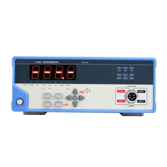
AT2511/511C User’s Guide 3. Start up This chapter provides the following information: Front Panel Summary Rear Panel Summary Power ON/OFF Connect to Device under Test 3.1 Front Panel 3.1.1 Front panel description Figure 3-1 Front panel Display Window 0.8 inches LED display measuring result... -
Page 11: Rear Panel Description
Start up Clear Perform short-circuit zero calibration. 3.1.3 Rear panel description Figure 3-2 Rear panel RS232C 。 Reserved port, this version does not use. Fuse Holder 250V,0.5A fuse AC Power Cord Receptacle 198V~242VAC,45Hz~55Hz 3.2 Power ON/OFF 3.2.1 Power up Power ON Power OFF 3.2.2 Warm-up time AT2511/511C is ready to be used as soon as the power-up sequence has completed. -
Page 12: Select Test Speed
AT2511/511C User’s Guide SENSE+ SENSE- DRIVE+ DRIVE- To make sure instrument’s accuracy, please use the “Kalvin Test Clip” that follows the instrument to test. No putting current source, voltage source directly access test side. Energy storage device access to testing after discharging. 3.4 Select Test Speed 2 test speed is available for the instrument: Slow :... -
Page 13: Clear Zero
Start up Table 3-1 Range no., reference Resistance and Range change process Reference Resistance 50mΩ 50mΩ 49mΩ 500m 500m 490m 5 5 4.9 50 50 49 500 500 490 5k 5k... -
Page 14: Setup Menu(Only Available For At2511
AT2511/511C User’s Guide The following example is wrong! Figure 3-5 Wrong way 2 . Press ESC to retreat Clear, press Enter to begin clearing, the instrument will clear zero all ranges. 3 Data will be saved in the nonvolatile memory when zeroing is over. .... -
Page 15: Turn On Comparator
Start up 3.7.1 Turn on comparator There are 2 ways for comparator to compare: 1. GD/NG compare. Under this way, instrument has 2 status indication: if exceeding upper and lower limit, it is regarded as NG; if within upper and lower limit, it is GD indication. 2. -
Page 16: Specification
AT2511/511C User’s Guide 4. Specification This chapter provides the following information: Technical Specifications General Specifications Dimension 4.1 Technical Specifications The following data are measured under the following conditions: Temperature:20℃±5℃ Humidity: 80% R.H. Zero Correction: Zeroing before testing Warm up:60 minutes and more Calibration Time:6 months Sample Speed:Slow: 3 times/sec... -
Page 17: Dimension
Operating: T 10℃~40℃ H 10~90% RH Storage: T 0℃~50℃ H 10~90% RH Accessories: User’s manual, ATL503 Kalvin test leads, AC power cord, test report, warranty card, backup fuse 4.3 Dimension Figure 4-1 dimension -AT2511/511C User’s Guide- ©2005-2014 Applent Instruments Ltd.
Need help?
Do you have a question about the Anbai AT2511 and is the answer not in the manual?
Questions and answers