Table of Contents
Advertisement
Quick Links
User's Guide
Rev.A
~
AT5210
Multi‐channel Battery Meter
®
@
Applent Instruments Ltd.
Address:
3 Floor, No. 61, Baolong International,
Changzhou, Jiangsu, China
Post Code: 213014
Tel: 0086-0519-88805550
Fax: 0086-0519-86922220
Sales Email: sales@applent.com
Tech Email: tech@applent.com
http://www.applent.com
(PRC)
Advertisement
Table of Contents

Subscribe to Our Youtube Channel
Related Manuals for Applent Instruments AT5210


Summary of Contents for Applent Instruments AT5210
- Page 1 User’s Guide AT5210 Rev.A Multi‐channel Battery Meter Applent Instruments Ltd. Address: 3 Floor, No. 61, Baolong International, Changzhou, Jiangsu, China (PRC) Post Code: 213014 Tel: 0086-0519-88805550 Fax: 0086-0519-86922220 ® Sales Email: sales@applent.com Tech Email: tech@applent.com http://www.applent.com...
-
Page 2: Certification, Limited Warranty, & Limitation Of Liability
CERTIFICATION, LIMITED WARRANTY, & LIMITATION OF LIABILITY Applent Instruments, Ltd. ( shortened form Applent ) certifies that this product met its published specifications at the time of shipment from the factory. Applent further certifies that its calibration measurements are traceable to the People’s Republic of China National Institute of Standards and Technology, to the extent allowed by the Institution’s calibration facility or by the calibration facilities of other International... -
Page 3: Table Of Contents
Unpacking and Preparation Contents CERTIFICATION, LIMITED WARRANTY, & LIMITATION OF LIABILITY ..................2 Contents ........................................3 Figure Contents ......................................5 Table Contents ......................................5 Unpacking and Preparation ................................. 7 Incoming Inspection ................................7 Power requirements and setting up Fuse ........................7 Environmental Requirements ............................ - Page 4 AT5210 User’s Guide <SYSTEM CONFIG> Page ............................... 23 6.1.1 【LANGUAGE】 ................................ 23 6.1.2 [DATE], [TIME] ................................24 6.1.3 【KEY BEEP】Setting .............................. 24 6.1.4 【BAUD] Rate Setup ............................... 24 6.1.5 RS-232 Shake Hand [SHAKE HAND] ......................... 25 <SYSTEM INFORMATION> ............................25 PLC (Handler) Interface ..................................
- Page 5 Figure 3-1 Front panel ..................................12 Figure 3-2 Rear panel ................................... 12 Figure 3-3 Test terminal for each channel ............................. 13 Figure 4-1 AT5210 <MEAS DISPLAY> page ..........................15 Figure 5-1 <Setup> page ................................... 17 Figure 5-2 Correct method of short-circuit clear zero ......................19 Figure 5-3 <Comp Setup>...
- Page 6 AT5210 User’s Guide...
-
Page 7: Unpacking And Preparation
Please use the following fuse type. UL/CSA type, Slow-Blow, 5×20-mm miniature fuse, 1A, 250 V When you need a fuse, contact your nearest Applent Instruments sales or service office. To verify and replace the fuse, remove the power cable and pull out the fuse holder. -
Page 8: Environmental Requirements
Vibration: Max. 0.5 G, 5 Hz to 500 Hz 1.4 Cleaning To prevent electrical shock, disconnect the AT5210 power cable from the receptacle before cleaning. Use a dry cloth or a cloth slightly dipped in water to clean the casing. - Page 9 Unpacking and Preparation Figure 1‐1 How to remove the handle 1 Retracted 3 Carrying Position 2 Extended Remove Handle(Lift the handle perpendicular to the unit while pulling it in the direction of 1.)...
-
Page 10: Overview
10 channels resistance and voltage can be output by Handler interface. AT5210 is equipped with RS232 interface and Handler interface to apply to remote control, data acquisition and analysis. SCPI (Standard Command for Programmable Instrument) to efficiently realize remote control and data acquisition function. -
Page 11: Trigger Mode
Overview Medium: 3s/10 channels Fast: 2s/10 channels 2.2.3 Trigger Mode Internal、External、Manual and Remote 2.2.4 Basic Accuracy Slow、Medium:0.5% Fast:1% 2.2.5 Correction Short-circuit Clear Zero correction for all ranges. 2.2.6 Comparator Function(Sorting Function) Each channel can independently set up comparator. Resistance GD signal or voltage GD signal output independently. Configurable outpur signal: ROK/VOK/R+VOK。... -
Page 12: Startup
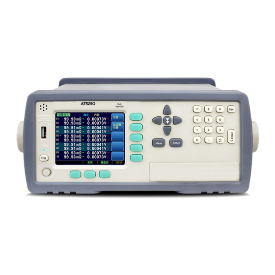
AT5210 User’s Guide 3. Startup This chapter describes names and functions of the front panel, rear panel, and screen display and provides the basic procedures for operating AT5210. Front panel summary Rear panel summary Power On/Off ... -
Page 13: Power On/Off
3.2.1 Power ON Power ON. Power OFF. AT5210 is ready to be used as soon as the power-up sequence has completed. However, to achieve the accuracy rating, warm up the instrument for 30 minutes. 3.3 Connect to Device under Test (DUT) Instrument’s test terminal is at rear panel, please go with rabbet direction and insert test... - Page 14 AT5210 User’s Guide Warning:NO measuring batteries with more than 60VDC, otherwise, it will cause damage to the instrument.
-
Page 15: Meas] Page
01-10 – channel setup Figure 4‐1 AT5210 <MEAS DISPLAY> page 4.1.1 【Trigger】 Mode SCPI command:TRIGger:SOURce {INT,MAN,EXT,BUS} 4 trigger modes are available for AT5210: INT (internal), EXT (external), MAN (manual) and BUS (RS-232) Trigger Mode Description Continuously repeats the measurement cycle. Performs one cycle of measurement each time you press the [Trig] key. -
Page 16: Channel】 Setup
AT5210 User’s Guide BUS Trigger by RS232 SCPI command 4.1.2 【Channel】 Setup SCPI command:FUNCtion:SCAN {ON,OFF,<CH NO.>} Each channel can be turned on/off or single channel test. Procedure to set up channel working mode: Step 1 Press [Meas] key to enter <MEAS DISPLAY>Page;... -
Page 17: Setup] Page
Trigger – trigger mode Range – measuring range speed – measuring speed Scan – scan method Figure 5‐1 <Setup> page 5.1.1 【Trigger】Mode SCPI command:TRIGger:SOURce {INT,MAN,EXT,BUS} 4 trigger modes are available for AT5210: INT (internal), EXT (external), MAN (manual) and BUS (RS-232) -
Page 18: Range
External Trigger Mode BUS Trigger by RS232 SCPI command 5.1.2 【Range】 SCPI command: FUNCtion:RANGe {<Range NO.>,min,max} 5 ranges are available for AT5210, changes for each range is as below: AT5210 only use manual range to make measurement: Table 5‐1 Range Range Range... -
Page 19: Measuring【Speed
5.1.3 Measuring【Speed】 SCPI command:FUNCtion:RATE {SLOW,MED,FAST,ULTRA} 3 measuring speed is available for AT5210,(Slow、Medium、Fast) 。The slower the measuring speed, the more the accuracy, the more stable. When all channels are turned on, and the range method is manual, the speed is as below:... -
Page 20: Comparator Setup
AT5210 User’s Guide Procedure to perform short-circuit clear zero Step 1 Press【Setup】to enter Setup page Step 2 Short clamp test clip Step 3 Use function key to select 【Clear】 Step 4 Press【OK】 ,instrument starts to perform clear zero Step 5 Return to Setup page after the process is completed 5.3 Comparator Setup... -
Page 21: Comp】Switch
[Setup] Page 5.3.1 【Comp】switch SCPI command:COMParator[:STATe] {ON,OFF,1,0} Procedure to turn on/off comparator Step 1 Press 【Meas】 or【Setup】to enter correspond page Step 2 Press 【Comp Setup】key Step 3 Use cursor keys to select 【Comp】field Step 4 Use function keys to select Function keys Function Comparator is turned off... -
Page 22: Lower Limit】And【Upper Limit】Setup
AT5210 User’s Guide 5.3.4 【Lower limit】and【Upper limit】setup Command format : COMParator:rbin <channel NO.1~10>,<resistance lower limit>,< resistance upper limit> Command format:COMParator:vbin < channel NO 1~10>,< voltage lower limit>,< voltage upper limit> Input direct reading limit value Step 1 Enter < Comp> page Step 2 Use cursor keys to select【1】... -
Page 23: System Config> Page
<SYSTEM CONFIG> Page 6. <SYSTEM CONFIG> Page This chapter describes: SYSTEM CONFIG SYSTEM INFORMATION SYSTEM SERVICE 6.1 <SYSTEM CONFIG> Page Press [SYSTEM] soft-key to enter <SYSTEM CONFIG> page. LANGUAGE – Choose English or Chinese Language DATE/TIME ... -
Page 24: Date], [Time]
Key beep is set to ON. 6.1.4 【BAUD] Rate Setup Before you can control the AT5210 by issuing RS-232 commands from built-in RS-232 controller connected via its DB-9 connector, you have to configure the RS-232 baud rate. The AT5210 built-in RS-232 interface uses the SCPI language. -
Page 25: Rs-232 Shake Hand [Shake Hand]
Best for communication with PC 6.1.5 RS-232 Shake Hand [SHAKE HAND] AT5210 supports software “shake hand”. AT5210 will return the whole command to host and then response the command when the [SHAKE HAND] is turned Procedure to turn ON the “Shake Hand”: Step 1 Press bottom soft-key [SYSTEM] to enter <SYSTEM CONFIG>... - Page 26 AT5210 User’s Guide...
-
Page 27: Plc (Handler) Interface
(GD/NG), and so on to external devices from the AT5210. You can also input the external trigger signal and the comparator select signal to the AT5210. With this interface and the comparator function, you can build an automatic screening system composed of the AT5210 and the handler. -
Page 28: Connection
AT5210 User’s Guide <Remark> CH2-V/RV 0:V-OK or RV-OK CH3-V/RV 0:V-OK or RV-OK CH4-V/RV 0:V-OK or RV-OK CH5-V/RV 0:V-OK or RV-OK CH6-V/RV 0:V-OK or RV-OK CH7-V/RV 0:V-OK or RV-OK CH8-V/RV 0:V-OK or RV-OK CH9-V/RV 0:V-OK or RV-OK CH10-V/RV 0:V-OK or RV-OK <Remark>:... - Page 29 PLC (Handler) Interface VCC(5V): 34-35 GND: 27-30 Electrical Characteristics Power requirements:+3.3V~35VDC Output signals: collector output of built-in pull-up resistor. Darlington drive, low level is valid. MAX voltage: supply voltage Input signals: opto-isolator. low level is valid. MAX current: 50mA Tip:To avoid the damage to interface, supply voltage can not exceed power requirement.
-
Page 30: Remote Control
Select Baud Rate. About SCPI AT5210 can use the RS-232 interface to communicate with the computer to complete all the instrument functions. 8.1 RS-232C RS-232 is currently widely used serial communications standard, is also called asynchronous serial communications standard, it is applied to realize communication of PC and PC、 PC and peripheral. -
Page 31: Handshake Protocol
Remote Control Tip: In order to avoid electrical shock, please disconnect power when insert and pull the connector. Instrument’s default communications setting: Transmission mode: includes full duplex asynchronous communication of start bits and stop bits Data bits: 8-bit Stop bits: 1-bit Parity bits: None 8.2 Handshake Protocol Instrument adopts RS-232C standard minimum subset, and software handshake to reduce... -
Page 32: Scpi Command Reference
AT5210 User’s Guide 9. SCPI Command Reference This chapter includes the following content: Terminator Command Syntax Query Syntax Query Response Command Reference This chapter provides descriptions of instrument’s available SCPI commands sets, which can complete all the instrument functions. -
Page 33: Command Structure
SCPI Command Reference 9.1.3 Command Structure The SCPI commands are tree structured three levels deep. The highest level commands are called the subsystem commands in this manual. So the lower level commands are legal only when the subsystem commands have been selected. A colon (:) is used to separate the higher level commands and the lower level commands. -
Page 34: Separator
AT5210 User’s Guide <integer> integer 123, +123, -123 <float> floating number 1. <Fixfloat>:fixed point floating number:1.23, -1.23 2. <Scifloat>:scientific notation floating number:1.23E+4, +1.23e-4 3. <Mpfloat>: multiplier expressed by floating number: 1.23k, 1.23M,1.23G,1.23u Table 9‐1 Multiplier Mnemonics Definition Mnemonic 1E18 (EXA) 1E15 (PETA) -
Page 35: Display Subsystem
SCPI Command Reference 9.4 DISPlay SUBSYSTEM DISPlay subsystem is used for switching different display page or display a string of text on page reminder bar. Figure 9‐2 DISPlay SUBSYSTEM tree DISPlay :PAGE {MEASurement, SETUp,COMParator,SYSTem,SYSTEMINFO(SINF)} :LINE <string> 9.4.1 DISPlay:PAGE DISP:PAGE is used for switching to an appointed page. Command Syntax DISPlay:PAGE <page name>... -
Page 36: Function:rate
AT5210 User’s Guide min range=1 max range=5 Example SEND> FUNC:RANG 5 //switch to Range NO. 5(1kΩ) Query Syntax FUNC:RANG? Query Range NO.1~5 Response Example SEND> FUNC:RANGE? RET> 5 9.5.2 FUNCtion:RATE FUNC:RATE is used for setting measuring speed. Command Syntax FUNCtion:RATE {SLOW,MED,FAST } Example SEND>... -
Page 37: Comparator:output
SCPI Command Reference Command Syntax COMParator:MODE {IDENtical,INDEpendent} Example SEND> COMP:MODE identical //uniform setting mode of comparator upper limit and lower limit Query Syntax COMP:MODE? Query {identical,independent } Response 9.6.3 COMParator:OUTPut COMP:OUTPut is used for setting Handler signal output mode. Command Syntax COMParator:OUTPut {R+V,R+RV} Example SEND>... -
Page 38: Trigger:source
AT5210 User’s Guide 9.7.2 TRIGger:SOURce TRIG:SOUR is used for setting trigger source Command Syntax TRIGger:SOURce {INT,MAN,EXT,BUS} Example SEND> TRIG:SOUR BUS //Set as BUS trigger mode. Query Syntax TRIG:SOUR? Query <INT,MAN,EXT,BUS> Response 9.7.3 TRG TRG when trigger source set as BUS, it generates a trigger and return trigger measuring data. -
Page 39: System:sendmode
RET> Short Clear Zero Start. //clear zero starts RET> PASS //clear zero success(FAIL) 9.11 IDN? SUBSYSTEM Figure 9‐9 IDN? SUBSYSTEM tree IDN? IDN? SUBSYSTEM is used for returning instrument version number. Query Syntax IDN? Query <model>,<version number>,<serial number>,<manufacturer> Response Example SEND> IDN? RET> AT5210,REV A1.0,0000000,Applent Instruments... - Page 40 AT5210 User’s Guide 10. Specifications This chapter describes: Technical Specifications General Specifications Dimensions 10.1 Technical Specifications The data as below is acquired by the following conditions: Temperature: 23°C±5°C Humidity: 65% R.H. Adjustment:short-circuit clear zero before measurement Warm-up Time:...
- Page 41 65% RH Operation: temperature 10℃~40℃ humidity 10~80% RH Storage: temperature 0℃~50℃ humidity 10~90% RH Power supply: 220VAC(1±10%) Fuse: 250V 1A Slow-Blow Power: MAX 20VA Wright: About 5kg 10.3 Dimensions (Dimensions) @Instruments -AT5210 User’s Guide- English ©2005-2017 Applent Instruments Ltd.
Need help?
Do you have a question about the AT5210 and is the answer not in the manual?
Questions and answers