Table of Contents
Advertisement
Quick Links
Contents
User's Guide
Rev.A1
FIRMWARE REVISIONS
This manual applies directly
to instruments that have
the firmware Rev. C7
AT381x
LCR Meter
Applent Instruments Ltd
No.61-3, Baolong International,Chahua Road, Zhonglou
District ,Changzhou City, Jiangsu Province, China
[213014]
Tel: 0519-88805550 Fax: 0519-86922220
http://www.applent.com
Sales Email:
sales@applent.com
Tech Email:
tech@applent.com
©2005-2018 Applent Instruments Ltd.
1
Advertisement
Table of Contents

Related Manuals for Applent Instruments AT381 Series


Summary of Contents for Applent Instruments AT381 Series
- Page 1 LCR Meter to instruments that have the firmware Rev. C7 Applent Instruments Ltd No.61-3, Baolong International,Chahua Road, Zhonglou District ,Changzhou City, Jiangsu Province, China [213014] Tel: 0519-88805550 Fax: 0519-86922220 http://www.applent.com Sales Email: sales@applent.com Tech Email: tech@applent.com ©2005-2018 Applent Instruments Ltd.
-
Page 2: Safety Summary
WARNING DANGER: When you notice any of the following abnormal conditions, terminate operation immediately and disconnect the power cord. Contact Applent Instruments Sales for repair. Failure to do so may result in fire or potential electrical shock to operators. Instrument is operating abnormally. -
Page 3: Certification, Limited Warranty, & Limitation Of Liability
Contents CERTIFICATION, LIMITED WARRANTY, & LIMITATION OF LIABILITY Applent Instruments, Inc. (shortened form Applent)certifies that this product met its published specifications at the time of shipment from the factory. Applent further certifies that its calibration measurements are traceable to the People’s Republic of China National Institute of Standards and Technology, to the extent allowed by the Institution’s calibration facility or by the calibration facilities of other International Standards Organization... -
Page 4: Table Of Contents
Contents Safety Summary ......................................2 Safety Information ....................................2 CERTIFICATION, LIMITED WARRANTY, & LIMITATION OF LIABILITY..................3 Contents ........................................4 Figure Contents ...................................... 10 Table Contents ......................................12 Unpacking and Preparation ................................13 Packing List ..................................13 Power Requirements ................................ 13 Operating Environment ..............................13 Cleaning .................................... - Page 5 Contents 3.2.2 Warm-up Time ................................23 Connect to Device under Test (DUT) .......................... 23 [Meas] Page ....................................... 25 <MEAS DISPLAY> Page ..............................25 4.1.1 Measurement Function [FUNC] .......................... 25 4.1.2 Impedange Range [RANGE] ..........................27 4.1.3 Test Frequency [FREQ] ............................28 4.1.4 Trigger Mode [TRIG] ...............................
- Page 6 5.4.1 Sweep Trigger Mode [TRIG] ..........................50 5.4.2 List Sweep Parameters Setup ..........................51 5.4.3 Configure the sweep points ..........................51 5.4.4 Limit parameters [CMP] selection........................51 5.4.5 Input [Lower] and [Upper] Limits Value ......................52 System Configurations ..................................53 <SYSTEM CONFIG>...
- Page 7 Contents 10.4.3 Separator ..................................71 10.4.4 Error Code .................................. 71 10.5 Command Reference ............................... 72 10.6 DISPlay Subsystem ................................72 10.6.1 DISP:PAGE ................................... 73 10.6.2 DISP:LINE ..................................73 10.7 FUNCtion Subsystem ............................... 74 10.7.1 FUNCtion ..................................74 10.7.2 FUNCtion:IMPedance:AUTO ..........................74 10.7.3 FUNCtion:IMPedance:RANGe ..........................
- Page 8 10.14.3 CORRection:SPOT:FREQuency ..........................87 10.14.4 CORRection:SPOT:OPEN............................87 10.14.5 CORRection:SPOT:SHORt ............................87 10.15 TRIGger Subsystem ................................88 10.15.1 TRIGger[:IMMediate] .............................. 88 10.15.2 TRIGger:SOURce ..............................88 10.15.3 TRIGger:DELAY ................................. 88 10.16 BIAS Subsystem ................................. 89 10.17 FILE Subsystem................................... 89 10.17.1 FILE?....................................89 10.17.2 FILE:SAVE ..................................
- Page 9 Contents 12.3.3 Range Mode Register【3002】 ........................107 12.3.4 Test Speed Register【3003】 ..........................108 12.3.5 Average Times Register【3004】 ........................109 12.3.6 Trigger Mode Register【3005】 ........................109 12.3.7 Test Frequency Register【3006】 【3007】 ....................110 12.3.8 Test Voltage Register【3008】 【3009】 ......................110 12.3.9 DCR Range Register【300A】...
- Page 10 13.3.3 Test signal level accuracy test ........................... 131 13.3.4 Frequency accuracy test ............................131 13.3.5 Capacitance C, loss D accuracy test ........................ 131 13.3.6 Inductance L accuracy test ..........................131 13.3.7 Impedance Z accuracy test ..........................131 Examples ....................................133 14.1 Basic Measurement Procedure ...........................
- Page 11 Contents Figure 10-1 Command Tree Structure ............................70 Figure 11-1 Modbus Command Frame ........................... 93 Figure 11-2 Modbus append CRC-16 value ........................... 94 Fiture 11-3 Normal response frame ............................95 Figure 11-4 Abnormal response frame ............................ 95 Figure 11-5 Read Multiple Registers(0x03) ........................96 Figure 11-6 Read Multiple Registers(0x03)Response Frame ..................
- Page 12 Table Contents Table 2-1 Series-parallel equivalent circuit ........................17 Table 2-2 AT381x Measurement display range ........................ 18 Table 2-3 Test signal accuracy ..............................19 Table 3-1 Front Panel Description ............................22 Table 4-1 The combinations of measurement parameters ..................26 Table 4-2 The combinations of monitor parameters ....................
-
Page 13: Unpacking And Preparation
1. Check appearance of the product whether there is damage, scratches, etc.; 2. Check the instrument packing list if there are any missing items. If there is any damage or insufficient accessories, please contact Applent Instruments Sales or distributor immediately. - Page 14 the AT381x internally. WARNING: Don’t Use Organic Solvents (such as alcohol or gasoline) to clean the instrument.
-
Page 15: How To Remove The Handle
Unpacking and Preparation How to Remove the Handle Instrument handle can be adjusted. Hold both sides of the handle with both hands, gently pull it to the sides, then rotate the handle. The handle can be adjusted to four positions as shown below: Figure 1-1 Instrument handle (schematic, panel graphics do not match the actual) -
Page 16: Overview
Remove handle position. (Pull to both sides until the handle is removed.) 2. Overview This chapter contains general information about AT381x. The information is organized as follows Introduction ⚫ Measurement Function ⚫ Signal Source ⚫ Main Functions ⚫ Introduction Thank you for purchasing AT381X LCR meter. AT381X is precision LCR meter that uses a fully automated real-time inspection micro-desktop instrument controlled by high-performance 32-bit ARM microprocessor. -
Page 17: Measurement Function
Overview programmable 9 qualified file, 1 auxiliary file (secondary-parameter unqualified), 1 unqualified file and primary parameter HI/IN/LO file, can set percentage points or absolute value sorting, equipped with Handler interface and RS-232C interface, used in automatic sorting system to complete automatic pipeline testing. An optional USB memory interface allows users to save setup data and measurement data to an external mover. -
Page 18: Range
Cs=(1+D D=1/2FCpRp=1/Q Rs=RpD /(1+D Cp=Cs/(1+D D=2FCsRs=1/Q Rp=Rs(1+D Definition for Q、D、Xs is:Q=Xs/Rs,D=Rs/Xs,Xs=1/2πFCs=2πFLs Generally, a series equivalent circuit is used for components having a low impedance value Z (for example, a high value capacitor and a low value inductor); a parallel equivalent circuit is used for a component having a large impedance value Z (low value Suggestion:... -
Page 19: Signal Source
Overview Parameter Measurement display range 0.00001nH ~ 9999.99H 0.00001pF ~ 9999.99mF R、X、Z 0.00001Ω ~ 99.9999M B、G 0.01nS ~ 999.999S 0.00001 ~ 9.99999 0.00001 ~ 99999.9 θd -179.999°~179.999° θr -3.14159 ~ 3.14159 -999.999% ~ 999.999% Signal Source 2.3.1 Test Frequency AT3818: 10Hz~300kHz continuous test frequency AT3816A:... -
Page 20: Main Functions
Main Functions 2.4.1 Correction Function Open clear zero: Eliminate effects of stray impedance on the test side and the instrument. The instrument can perform single-point, three-point frequency open circuit clear zero or sweep frequency (all typical frequency) open circuit clear zero. Short-circuit clear zero: Eliminate effects of series resistance and inductance of the leads. -
Page 21: System Settings
Overview 3. Setting data in <Setup List Sweep> page 2.4.5 System Settings Keyboard lock function 2. Administrator and user accounts, which can set passwords for administrators 2.4.6 Interface USB Host Interface: Used to save screen images, save setup parameters and measurement data on a USB flash drive. -
Page 22: Startup
3. Startup In this chapter you will learn the following: Front panel – including the introduction of buttons and test terminals. ⚫ Rear panel – describes the power and interface information. ⚫ Power on—including power on self-test process, instrument defaults, ⚫... -
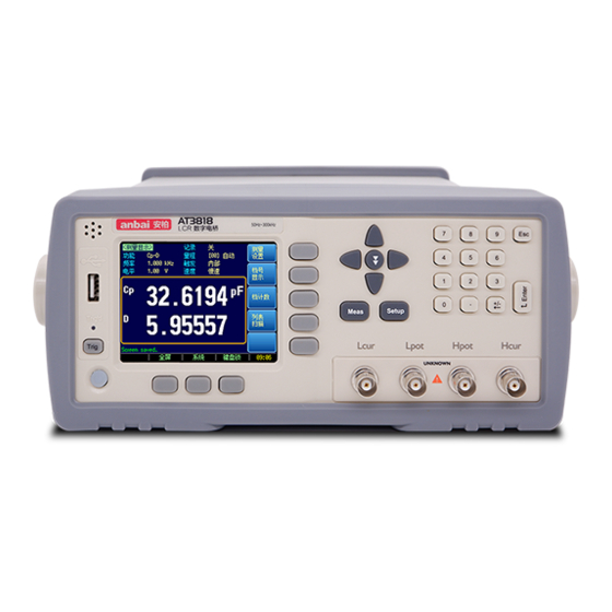
Page 23: Rear Panel
Startup Hcur high terminal - current side Hpot high terminal - voltage side Lpot low terminal - voltage side Lcur low terminal - current side Numeric keypad Cursor key LCD Display 3.1.2 Rear Panel Figure 3-2 Rear panel Power Cable Receptacle (Outlet) GND. - Page 24 Warning: Do not apply DC voltage or current to the test terminal, otherwise the instrument will be damaged. WARNING: If test a charged device, make sure that its charge is removed before measuring. • Test fixtures and cables: We recommend that users use our test fixtures or test cables, if using test fixtures or cables made by user or other company may result in incorrect measurements.
-
Page 25: Meas] Page
[Meas] Page 4. [Meas] Page This section includes the following information: MEAS DISPLAY page • BIN No. page • • BIN COUNT page LIST SWEEP page • <MEAS DISPLAY> Page Press [Meas] key to enter <MEAS DISPLAY> page. <Meas Display> page mainly highlights measurement results and displays the current sorting result in small characters. - Page 26 monitor parameters. The monitor parameters need to be set in [Setup] page. Note: The monitor parameters are initially set to OFF. Types of measurement parameters: Table 4-1 The combinations of measurement parameters Cs-Rs Cs-D Cp-Rp Cp-D Lp-Rp Lp-Q Ls-Rs Ls-Q Rs-Q Rp-Q Z-r...
-
Page 27: Impedange Range [Range]
[Meas] Page 4.1.2 Impedange Range [RANGE] Table 4-4 Impedance range mode Mode Function overview Advantage Disadvantage Auto range requires Auto instrument automatically Users do not need predictive range and range selects the best test range based any participation test speed will on impedance value. -
Page 28: Test Frequency [Freq]
When range is automatic, the instrument will perform range prediction for each measurement cycle, so test speed will be slightly slower than hold range. Moreover, frequent Note: changes in the range during automatic measurement can slow down the response. Usually, when instrument is used as a sorting measurement, auto range method is not suitable. -
Page 29: Trigger Mode [Trig]
[Meas] Page 10Hz 50Hz 60Hz 100Hz 120Hz 1kHz 10kHz 20kHz 40kHz 50kHz 100kHz Table 4-10 AT3810A List of the most common frequencies INCR +/ DECR - 10Hz 50Hz 60Hz 100Hz 120Hz 1kHz 10kHz 20kHz 4.1.4 Trigger Mode [TRIG] The instrument has 4 trigger modes: Internal trigger, manual trigger, external trigger and remote trigger. -
Page 30: Measurement Speed [Speed]
Step 1 Press [Meas] to enter Meas page; Step 2 Press [Meas Display] key to switch to < Meas Display> page; Step 3 Use the cursor keys to select [Level] field; Step 4 Users can: Use soft keys to increase or decrease the level Input data directly, soft key to select voltage or current unit. -
Page 31: Record] Data
[Meas] Page SLOW 1600 1600 88.5 88.5 88.5 FAST 1600 26.5 24.5 24.5 24.5 4.1.7 [Record] Data The instrument can record 10,000 sets of test data through the internal data buffer. These data are saved in an external USB disk in (.csv) file format. These files can be opened on a PC using a Windows Excel. -
Page 32: Bin No. Display> Page
<BIN No. DISPLAY> Page Press [Meas] key and use soft key to enter the [BIN No. DISPLAY] page. Figure 4-2 <BIN No. DISPLAY> page Setting Bar: The setting area of bin number display page is roughly same as the [Meas Display] page. -
Page 33: Auxiliary Bin [Aux] On/Off
[Meas] Page Sorting Start BIN1 ≤Δor% ≤ BIN1 …… BIN9 ≤Δor% ≤ BIN9 Primary parameter pass Display BIN1 – BIN9 ≤ D ≤ D ≤ Q ≤ Q GOOD Output SREJ Display GD Output GD Not Good Display NG AUX ON/OFF? Output NG Display AUX Output AUX... -
Page 34: Information Bar Of [Bin No. Display]
4.2.3 Information Bar of [Bin No. Display] The information bar shows the settings associated with the comparator, including nominal value, comparator mode, secondary parameter limit value, and the limit range for bin 1. At the same time, correction information is also displayed in the information bar too. <BIN COUNT DISPLAY>... -
Page 35: List Sweep Display> Page
[Meas] Page <LIST SWEEP DISPLAY> Page The <LIST SWEEP DISPLAY> page will display when you press the [Meas] key and [LIST SWEEP] soft key. Figure 4-5 <LIST SWEEP DISPLAY> page <List Sweep Display> cycle sweeps 10 groups of frequencies or levels and compare them with the set values to get the comparison result. -
Page 36: Sweep [Method] Settings
4.4.2 Sweep [Method] Setting The <List Sweep Display> page completes the scan frequency or level value test of up to 10 list points. When the test [Method] is set to sequence and [Trigger] is set to manual, the sweep function will automatically execute each test step on the list in sequence until the last step. -
Page 37: Setup] Key
[Setup] Key Step 1 Press the [Meas] key; Step 2 Press the bottom soft key [Full Screen] to switch to <Measure Full Screen Display> 5. [Setup] Key In this chapter users will learn about all the setup features: Meas Setup page •... -
Page 38: Source Output Impedance [Src Res]
5.1.1 Source Output Impedance [SRC RES] The source internal resistance is also called the output impedance. The Source output impedance can be set to 30, 50 or 100. After the test level Vs is set, the test current is flowing through the device under test (DUT) will be determined by the impedance Zx=Rx+jXx of the DUT and the source internal resistance Rs, namely: Since some measured components such as high-permeability magnetic core inductors will... -
Page 39: Dc Bias Voltage
[Setup] Key Step 3. Use the soft keys or number keys to enter averaging factor. Soft key Function INCR + Increments the averaging factor in steps of 1, 2, 4, 8, 16, 32, 64, 128 and 256. DECR - Decrements the averaging factor in steps of 1, 2, 4, 8, 16, 32, 64, 128 and 256. 5.1.3 DC Bias Voltage The instrument has built-in -2.5V~2.5V DC bias. -
Page 40: Measurement [Delay]
Soft key Function Turn off the monitor Absolute value of impedance Dissipation factor Quality factor(=1/D) Test signal Voltage Test signal Current Absolute deviation value Relative deviation value % Phase angle (radian) r d Phase angle Resistance (=Rs) Reactance Conductance Admittance 5.1.6 Measurement [Delay]... -
Page 41: Open Correction [Open]
[Setup] Key In this page, the OPEN/SHORT/LOAD correction for correcting the stray admittance and residual impedances can be performed. In order to achieve the accuracy specified by the technical specifications, open circuit clear zero and short circuit clear zero are necessary. Load calibration refers to the linear correction of the instrument using a known standard, which is usually not required by user. -
Page 42: Short Correction [Short]
[Open] correction will completely correct the typical frequency of the instrument. These frequency points vary depending on the instrument version: For these typical frequencies, please refer to the test frequency "List of frequently used frequencies". To perform open correction ◼ Step 1 Press the [Setup] key, then press [Correction] Step 2... -
Page 43: Frequency 1, 2, 3 Correction [Freq 1] [Freq 2] [Freq3]
[Setup] Key Step 1 Press the [Setup] key, then press [Correction] Step 2 Press the [CORRECTION] soft key. Step 3 Use the cursor key to select [SHORT] field Soft key Function Enables short correction. Disables short correction. The clear value does not participate in the measurement operation. - Page 44 Short correction Individually perform short correction for this set frequency Load correction Perform load correction for this set frequency Step 4 Press [MEAS OPEN] soft key, a dialog message display “Connect the UNKNOWN terminal without DUT”. Step 5 Please Connect the UNKNOW terminal and test fixture without DUT connected. Step 6 After pressing [OK], the instrument starts to perform correction.
-
Page 45: Comparator Setup
[Setup] Key Step 5 Move the cursor keys to select [Standard B], enter the secondary parameter value of the standard. For example, if the current [Function] is Cs-D, enter a known D value for [Standard B]. Step 6 Connect the standard to the terminal under test. Step 4 Move the cursor key to this frequency Soft key... -
Page 46: Function】 Setup
5.3.1 【Function】 Setup The instrument can be independently set up for all test functions and stored in internal memory space. Before setting the comparator parameters, select the consistent test [Function] according to the parameters set in the Meas page. 5.3.2 Comparator Function ON/OFF AT381x’s built-in comparator can sort devices into a maximum of 10 bins (BIN1 to BIN9 and OUT OF BIN) using a maximum of nine pairs of primary parameter limits and one pair of... -
Page 47: Figrue 5-7 Example Of Sorting In Tolerance Mode
[Setup] Key Among them: Nominal value: The tolerance mode requires input of the nominal value. ● Includes this point ○ Excludes this point Absolute value = measured value – nominal value Percent % = (measured value - nominal value) / nominal value × 100% Figrue 5-7 Example of sorting in tolerance mode ●... -
Page 48: Nominal Value For Tolerance Mode
In sequential mode, the comparison uses the direct reading measurement value to compare with the upper and lower limit ranges of the bin. The nominal value does not need to participate in operation. To set up the comparator limit mode: ◼... -
Page 49: Total Number Of Bins [#-Bins]
[Setup] Key Beep is off Beep when the comparator sorting result is GD Beep when the comparator sorting result is NG 5.3.7 Total Number of Bins [#-BINS] AT381x specify nine bins (1-BINS to 9-BINS). Please set number of bins according to your own requirements and close the extra bins. -
Page 50: List Sweep Setup> Page
overlapped. Please check the setting result carefully to prevent the sorting error. <LIST SWEEP SETUP> Page Press the [Setup] key and press [LIST SETUP] soft key to open the <LIST SWEEP SETUP> page. The list sweep feature of AT381x can perform automatic or manual sweep measurement by sweeping the frequency, signal level through a maximum 10 groups of frequencies or levels. -
Page 51: List Sweep Parameters Setup
[Setup] Key 5.4.2 List Sweep Parameters Setup The sweep parameter used in list sweep measurement can be measurement frequency and signal level. Use the sweep point field to specify the list sweep measurement parameter. To select the list sweep measurement parameter ◼... -
Page 52: Input [Lower] And [Upper] Limits Value
Not compare Do not compare 5.4.5 Input [Lower] and [Upper] Limits Value Each sweeping point has a set of upper and lower limits, which may be a sequential range of the primary parameter A or the secondary parameter B. The primary parameter A and secondary parameter B multiplex the same storage space to NOTE store upper and lower limits. -
Page 53: System Configurations
System Configurations 6. System Configurations This section includes the following information: SYSTEM CONFIG page • SYSTEM INFO page • • SYSTEM SERVICE page When press the [Meas] or [Setup] key followed by [SYSTEM] bottom soft key, the <SYSTEM CONFIG> page appears. <SYSTEM CONFIG>... -
Page 54: Setting The System Date And Time
Soft key Function Chinese Language ENGLISH English Language 6.1.2 Setting the system date and time AT381x features a built-in 24-hour clock. To change the date: ◼ Step 1 Enter <SYSTEM CONFIG> page Step 2 Use the cursor key to select [Date] field Step 3 Use the soft keys to set date. -
Page 55: Beep Tone Setting
System Configurations Step 2 Use the cursor key to select [Account] field Step 3 Use the soft keys to set. Soft key Function CHANGE PASSWORD Input password (less than 9 numbers). DELETE PASSWORD The password will be removed. 6.1.4 Beep Tone Setting The beep tone setting allows beep tone to be turned on or off. -
Page 56: Terminator】Setting
computers, advanced equipment such as computer and industrial computer. Modbus: Industrial field bus protocol, binary transmission, suitable for host PLC and touch screen devices. To set up the communication protocol: Step 1 Enter <SYSTEM CONFIG> page Step 2 Use the cursor key to select [Communication Protocol] field Step 3 Use the soft keys to select. -
Page 57: Error Code】On/Off
System Configurations 6.1.9 【Error Code】ON/OFF When the error code is turned on, the AT381x will return the execution result of each instruction to the host. When the instruction is a query, the execution will return the result of the query correctly, and the execution error will return an error code. -
Page 58: Data Cache]
Soft key Function NOTE This setting and function is valid only under the SCPI protocol. 6.1.11 [Data Cache] Set the maximum data cache value for the Data [Record] function. The AT381x can set up to 10000 sets of cache data. After the cache setting value is reached, the data record will stop. This data can be saved in the external USB disk. -
Page 59: File Operation
File Operation 7. File Operation This chapter provides information on the file operation of the AT381x. The AT381x has built-in non-volatile memory, users can save system configuration data and user data in this memory. The system's built-in memory can save 10 configuration files. If you have the USB memory interface option installed, the data can also be saved in an external USB memory. -
Page 60: Recall A File At Startup [Auto Recall]
Soft key Function Internal Internal memory External USB storage 7.1.2 Recall a File at Startup [AUTO RECALL] Users can recall file0 or current file at the instrument starts up by setting the [AUTO RECALL] field. To select auto recall file Step 1 Enter <CATALOG>... -
Page 61: Plc(Handler)Interface
PLC(Handler)Interface 8. PLC(Handler)Interface This chapter provides information of AT381x’s built-in handler interface. Include: Pin Assignment ⚫ Circuit Diagram ⚫ Timing Chart ⚫ The instrument provides user with a full-featured processor interface that includes 14 bins sorting output, IDX (AD conversion end signal), EOM (test completion signal), TRIG (external trigger start) input, comparator record number input signal, etc. -
Page 62: How To Connection
O_S_OVER Secondary parameter output low level valid , AUX function is (NG) turned on O_P_OVER Primary parameter output low level valid (NG) O_P_HI Main measuring output (over low level valid higher limit) O_P_LO Main measuring output (over low level valid lower limit) O_NG BUS output (NG) -
Page 63: Timing Chart
PLC(Handler)Interface E XT .D CV INPU T 4 99 Output terminal schematic ◼ Figure 8-3 Typical Circuit Diagram of Handler Interface Output signals(sorting,IDX,EOM) E XT .DCV 4 .99 k O UT PU T G ND Maximum source current:5mA Maximum reverse current:50mA Timing Chart Recommended signal input and output timing chart ◼... - Page 64 Time Description Minimum Trigger pulse width Measurement Trigger delay time <10μs cycle ADC time (Related to measurement speed) Operation time Comparator result delay time 200μs Await next trigger 0μs...
-
Page 65: Remote Control
Remote Control 9. Remote Control This chapter provides the following information: About RS-232 Interface ⚫ RS-232 Connection ⚫ Select Baud Rate. ⚫ About SCPI ⚫ AT381x can use RS-232 interface to communicate with the computer to complete all the instrument functions. With standard SCPI commands, users can also easily create a variety of acquisition systems that are suitable for them. -
Page 66: How To Connect
Recommendation: To avoid electrical shock, turn off AT381x when connect or disconnect the connector. AT381x default communication settings: ◼ Transmission method: Full-duplex asynchronous communication with start and stop bits Data bits: 8-bit Stop bits: 1-bit Parity: none 9.1.2 How to Connect Figure 9-2 RS-232 interface on the rear panel [male] The RS-232 serial interface can be interconnected with a serial interface of a controller (eg PC... -
Page 67: Modbus(Rtu) Protocol
Remote Control code. In fact, for simple applications (such as PLC), you only need to translate the commands into HEX bytes and then transfer them in bytes. 9.3.1 Modbus(RTU) Protocol The Modbus protocol is a general-purpose language applied to electronic controllers and is mainly used for BUS protocols in industrial fields. -
Page 68: 10. Scpi Command Reference
10. SCPI Command Reference This chapter contains the following information: Terminator - rules of the terminator ⚫ Command syntax - command line writing rules ⚫ Query syntax - writing rules of query command ⚫ Query response - format of the query response ⚫... -
Page 69: Terminator
SCPI Command Reference CR+LF (Hexadecimal:0x0D 0x0A) NUL (Hexadecimal:0x00) The terminator can be selected in the system configuration page, and the instrument defaults is LF. Note: The AT381x allows the command sent by the host without the terminator, but it is ... -
Page 70: Command Structure
10.3.3 Command Structure The SCPI commands are tree structured three levels deep. The highest level commands are called the subsystem commands in this manual. So the lower level commands are legal only when the subsystem commands have been selected. A colon (:) is used to separate the higher level commands and the lower level commands. -
Page 71: Separator
SCPI Command Reference 1. <Fixfloat>:fixed point floating number:1.23, -1.23 2. <Scifloat>:scientific notation floating number:1.23E+4, +1.23e-4 3. <Mpfloat>: multiplier expressed by floating number: 1.23k, 1.23M,1.23G,1.23u Table 10-1 Multiplier Mnemonics Definition Mnemonic 1E18 (EXA) 1E15 (PETA) 1E12 (TERA) 1E9 (GIGA) 1E6 (MEGA) 1E3 (KILO) 1E-3 (MILLI) 1E-6 (MICRO) -
Page 72: Command Reference
*E04 INPUT BUFFER OVERRUN Receive buffer overflow, the maximum buffer of the AT381x is 1000 bytes *E05 SYNTAX ERROR Syntactic error *E06 INVALID SEPARATOR Invalid separator *E07 INVALID MULTIPLIER Invalid multiplier *E08 BAD NUMERIC DATA Value error *E09 VALUE TOO LONG The value is too long, the numeric parameter exceeds 20 bytes *E10... -
Page 73: Disp:page
SCPI Command Reference DIS P :PAGE MEASurement(MEAS) ENLARGEMEAS(ENME) BINMEAS (BINM,BNUM) BINCOUNT (BCO) LISTMEAS (LIST) SETUP (MSET) CORRECTION (CSET) BINSETUP (BSET) LISTSETUP (LSET) CATalog(FILE) SYSTem(SYST) SYSTEMINFO (SINF) “ ” :LINE <string> 10.6.1 DISP:PAGE The :PAGE command sets the display page. The :PAGE? Query returns the abbreviated page name currently displayed on the LCD screen. Command Syntax DISP:PAGE <page name>... -
Page 74: Function Subsystem
10.7 FUNCtion Subsystem The FUNCtion subsystem command group sets the measurement function, the measurement range, monitors parameter control. Figure 10-2 FUNCtion Subsystem Tree FUNCtion {Cs-Rs,Cs-D, Cp-Rp,Cp-D, Lp-Rp,Lp-Q, Ls-Rs,Ls-Q, R-Q,R-X, Z-thr(Z-θr),Z-Thd(Z-θd) Z-D,Z-Q, DCR} :IMPedance :AUTO {on,off,1,0} :RANGe <integer> :DCR :AUTO {on,off,nom} {off, Z, D, Q, :MONitor1 VAC, IAC,ABS, PER,... -
Page 75: Function:impedance:range
SCPI Command Reference Example SEND> FUNC:IMP:AUTO ON Query Syntax FUNC:IMPedance:AUTO? Query Response {on,off} SEND> FUNC:IMP:AUTO? Example RET> 10.7.3 FUNCtion:IMPedance:RANGe The FUNCtion:IMPedance:RANGe command sets the impedance’s measurement range. Command Syntax FUNC:IMPedance:RANGe <0-8,MIN,MAX> Where, <0-8,MIN, MAX> is: Parameter 0-8, The range number MIN, =Range 0 MAX, =Range 8 Example... -
Page 76: Frequency Subsystem
Example SEND> FUNC:MON1 Z FUNC:MON1? Query Syntax FUNC:MON2? Query Response {off, Z, D, Q, THR, THD, R, X, G, B, Y, ABS, PER VAC, IAC} SEND> FUNC:MON1? Example RET> 10.8 FREQuency Subsystem The FREQuency command sets the oscillator frequency. The FREQuency? Query returns the current test frequency setting. -
Page 77: Level:voltage (=Voltage[:Level])
SCPI Command Reference 10.9.1 LEVel:VOLTage (=VOLTage[:LEVel]) The LEVel:VOLTage or VOLTage[:LEVel] command sets the oscillator’s output voltage level. LEVel:VOLTage {<value>,MIN,MAX} Command Syntax or VOLTage:LEVel {<value>,MIN,MAX} Where, Parameter <value> is the numeric data (NR1, NR2 or NR3). MIN Sets to the minimum value of voltage MAX Sets to the maximum value Example SEND>... -
Page 78: Level:alc (=Amplitude:alc)
Note The suffix unit can’t be used with this command. This command CANNOT be used in LIST SWEEP DISPLAY page and CORRECTION page. 10.9.4 LEVel:ALC (=AMPlitude:ALC) The LEVel:ALC or AMPlitude:ALC command enables the Automatic Level Control (ALC). LEVel:ALC {on,1,off,0} Command Syntax AMPlitude:ALC {on,1,off,0} {on,1,off,0}... -
Page 79: Aperture:avg
SCPI Command Reference SEND> APER:RATE? Example RET> slow 10.10.2 APERture:AVG? The APERture:AVG? query returns the averaging rate settings. Query Syntax APER:AVG? <NR1> Query Response Integer (0 to 256) SEND> APER:AVG? Example RET> 10.11 FETCh Subsystem The FETCh subsystem command group is a sensor-only command which retrieves the measurement data taken by measurement(s) initiated by a trigger, and places the data into the output buffer. -
Page 80: Fetch:monitor1? /2
Query Syntax FETCh:MAIN? Query Response <NR3:primary value>,<NR3:secondary value> SEND> FETC:MAIN? Example RET> +2.021009e-11,+1.644222e-01//LCR Primary ,Secondary RET> +1.23434e+05//DCR 10.11.4 FETCh:MONitor1? /2? The FETCh:MONitor1? and FETCh:MONitor2 set the latest measurement data of the moniter1 and moniter2 parameters into the output buffer. Query Syntax FETCh:MONitor1? and FETCh:MONitor2? Query Response <NR3: moniter1/2 value>... -
Page 81: Comparator:state
SCPI Command Reference :S TATe COMParator {ON,OFF} :MODE {ABS,PER,SEQ} :AUX {ON,OFF} :BINS {1 to 9} :TOLerance :NOMinal <value> :BIN <n,low,high> :S ECONDARY(S LIM) <low>,<high> :BEEP {OFF,PASS,FAIL} :OPEN {OFF,2,5,10,20,50} 10.12.1 COMParator:STATe The COMParator:STATe command sets the comparator function to ON or OFF. Command Syntax COMParator:STATe {ON,OFF,1,0} Where,... -
Page 82: Comparator:aux
10.12.3 COMParator:AUX The COMParator:AUX command sets the auxiliary BIN counting function of the comparator to ON or OFF. Command Syntax COMParator:AUX {ON,OFF,1,0} Where,{ON,OFF,1,0} is: Parameter ON or 1 Set the AUX BIN to ON OFF or 0 Set the AUX BIN to OFF Example SEND>... -
Page 83: Comparator:slim
SCPI Command Reference Query Syntax COMParator:TOLerance:BIN? <n> Where,<n> is: Parameter NR1 (1 to 9): Bin number Query Response <NR3:low limit>,<NR3:high limit> SEND> COMP:TOL:BIN? 2 Example RET> 1.000000e-06,2.000000E-6 10.12.7 COMParator:SLIM The COMParator:SLIM or COMParator:secondary command sets the LOW/HIGH limit values for the secondary parameter. COMParator:SLIM <low value>,<high value>... -
Page 84: List Subsystem
10.13 LIST Subsystem The LIST or SWEEP Subsystem command group sets the List Sweep measurement function, including the sweep point setting and limit values for the limit function. Figure 10-8 LIST Subsystem Command Tree :PARAmeter LIS T {FREQ,VOLT,CURR} :S TAT <n>,{ON,OFF} :BAND <n>,<value>,{A,B,OFF},<low>,<high>... -
Page 85: Correction Subsystem
SCPI Command Reference Command Syntax LIST:BAND <n>,<point value>,{A,B,OFF},<low>,<high> Where, <n>,<point value>,{A,B,OFF},<low>,<high> is: Parameter NR1(1 to 10): List sweep point <point value> sweep point value (frequency value or signal level voltage value) Uses the primary parameter as the limit parameter. Uses the secondary parameter as the limit parameter. Turn off the List Sweep’s comparator function <low>... -
Page 86: Correction:open
:OPEN :S TATe CORRection {ON,OFF} :S HORt :S TATe {ON,OFF} :LOAD :S TATe {ON,OFF} :S POT :S TATe {ON,OFF} :FREQuency <n>,<value> :OPEN <n> :S HORt <n> :LOAD <n> :S TANdard <n>,<REF.A>,<REF.B> 10.14.1 CORRection:OPEN The CORRection:OPEN command execute all presetted OPEN correction data measurement points. -
Page 87: Correction:short
SCPI Command Reference 10.14.2 CORRection:SHORt The CORRection:SHORt command execute all presetted SHORT correction data measurement points. Command Syntax CORRection:SHORt SEND> CORRection:SHOR Example RET> short 10.14.2.1 CORRection:SHORt:STATe The CORRection:SHORt:STATe command sets the SHORT correction function to ON or OFF. Command Syntax CORRection:SHORt:STATe {ON,OFF,1,0} Where, {ON,OFF,1,0} is: Parameter... -
Page 88: Trigger Subsystem
10.15 TRIGger Subsystem The TRIGger subsystem command group is used to enable a measurement or a sweep measurement, and to set the trigger mode. Figure 10-10 TRIGger Subsystem Command Tree [:IMMediate] TRIGger :S OURce {INT,MAN,EXT,BUS} :DELAY(DLY) <float value>,min,max 10.15.1 TRIGger[:IMMediate] The TRIGger:IMMediate command causes the trigger to execute a measurement or a sweep measurement, regardless of the trigger state. -
Page 89: Bias Subsystem
SCPI Command Reference TRIGger:DLY? Query Response {0.000s~60.00s} SEND> TRIG:DLY? Example RET> 1.000s 10.16 BIAS Subsystem The BIAS subsystem command group sets the DC BIAS switch to ON or OFF, and sets the DC bias voltage value. Figure 10-11 BIAS Subsystem Command Tree BIAS {<-2.5V to +2.5V>, min,max}... -
Page 90: File:load
The FILE:SAVE <n> command saves all user settings into specified file. Command Syntax FILE:SAVE <File No.> Where, <File No.> is: Parameter NR1 (0 to 9) Example SEND> FILE:SAVE 0 10.17.3 FILE:LOAD The FILE:LOAD command recalls all user settings from current used file. Command Syntax FILE:LOAD Example... -
Page 91: System:code
SCPI Command Reference 10.19.2 SYSTem:CODE The SYSTem:CODE command feeds back error code for each sent command. Command Syntax SYSTem:CODE {on,off} Example SEND> SYST:CODE ON Query Syntax SYSTem:CODE? Query Response {on,off} SEND> SYST:CODE? Example RET> 10.19.3 SYSTem:KEYLock SYSTem:KEYLock command unlocks the keypad. SYST:KEYLOCK OFF Command Syntax or UNLOCK(UNLK) -
Page 92: Sav
10.20.3 *SAV *SAV = FILE:SAVE The *SAV command saves all user settings into current used file. Command Syntax *SAV Example SEND> *SAV 10.20.4 *RCL *RCL = FILE:LOAD The *RCL command recalls all user settings from current used file. Command Syntax *RCL Example SEND>... -
Page 93: 11. Modbus(Rtu)Protocol
Modbus(RTU)Protocol 11. Modbus(RTU)Protocol This chapter include the following information: Data format – About the Modbus communication format. ⚫ Function ⚫ Variable Area ⚫ Function Code ⚫ 11.1 Data Format We follow the Modbus (RTU) communication protocol, the instrument will respond to commands of the host computer and return the standard response frame. -
Page 94: Crc-16 Calculation Method
get the CRC16 check code At least 3.5 character time squelch interval is requested 11.1.2 CRC-16 Calculation Method Set the initial value of the CRC-16 register to 0xFFFF. Perform XOR calculation fo CRC-16 register and information of the first byte, then it return the result to the CRC register. -
Page 95: Response Frame
Modbus(RTU)Protocol 11.1.3 Response Frame Unless it is a command broadcast by 00H station address, the other station address will return a response frame by the AT381x. Fiture 11-3 Normal response frame Figure 11-4 Abnormal response frame Table 11-2 Description for abnormal response frame Station address 1 byte Returned from station address as it is... -
Page 96: Error Code
digit of 8, and the received digits are less than 8 or greater than 8 bytes. 5. When the station address is 0x00, it represents the broadcast address, the AT381x does not respond. 11.1.5 Error Code Table 11-3 Description for Error Code Error code Name Description... -
Page 97: Writing To Multiple Registers
Modbus(RTU)Protocol The function code for reading multiple registers is 0x03. Table 11-5 Read Multiple Registers Name Name Description Station address When there is no RS485 address specified, the default is 01. 0x03 Function code Starting address Register start address, please refer to the Modbus command set Number of read The number of registers read continuously. -
Page 98: Echo Test
Starting address Register start address, please refer to the Modbus command set Number of write The number of registers read continuously. Please registers refer to the Modbus command set to ensure that 0001~0068(104) these register addresses arevalid, otherwise an error frame will be returned. - Page 99 Modbus(RTU)Protocol Fixed value 00 00 Test data Any value: for example 12 34 CRC-16 Check code Example: Assume that the test data is 0x1234:...
-
Page 100: 12. Modbus(Rtu)Command
12. Modbus(RTU)Command This chapter contains the following information: Register overview ⚫ Detailed operation ⚫ Be sure to contact our sales department to obtain the communication test tool, which has Modbus communication debugging method. It contains CRC-16 Reference: calculator and floating point numbers converted into Modbus floating point format. - Page 101 Modbus(RTU)Command 0007 Ls-Q 0008 Rs-Q 0009 Rp-Q 000A 000B 000C 000D 000E 000F 3001 LCR range No. 0000~0008 Read and write registers, 2-byte integer 3002 Range mode 0000:Manual Read and write registers, 2-byte 0001:Auto integer 0002:Nominal 3003 Test speed 0000:Slow Read and write registers, 2-byte 0001:Medium1 integer...
- Page 102 0001:Comparator on integer 3101 Comparator mode 0000:ABS Read and write registers, 2-byte 0001:PER integer 0002:SEQ 3102 Secondary parameter comparison 0000: Secondary Read and write registers, 2-byte on/off parameter comparison integer 0001 : Secondary parameter comparison 3103 Bin count 0001~0009 Read and write registers, 2-byte Bin count 1~9bin integer 3104...
- Page 103 Modbus(RTU)Command limit value number occupies 2 registers 3128 Primary parameter BIN7 lower 4-byte floating point Read and write registers, data limit value number occupies 2 registers 312A Primary parameter BIN7 higher 4-byte floating point Read and write registers, data limit value number occupies 2 registers 312C...
-
Page 104: Obtain Measurement Data
oint frequency off 4-byte floating point number 5020 Point frequency open circuit 0001:Point frequency 1 Read and write registers, data correction 0002:Point frequency 2 occupies 1 register 0003:Point frequency 3 Read: 0000 correction success FFFF correction fail 5028 Point frequency short circuit 0001:Point frequency 1... -
Page 105: Obtain Comparator Results 【2004
Modbus(RTU)Command Obtain the secondary parameter measurement result: ⚫ Send: passive read register number of check code station registers Response: byte single precision floating point CRC-16 number Among them, B4~B6 is measurement data:501502F9 stands for 1E10(Low position in front) 12.2.2 Obtain Comparator Results 【2004】 Register 2004 records voltage and resistance comparator results 16-bit storage domain: Among them:... -
Page 106: Parameter Setting
passive read register number of check code station registers Response: 01 03 0A 44 79 D4 B1 37 D6 9D C2 00 81 C6 24 12.3 Parameter Setting 12.3.1 Function Register【3000】 Write ⚫ write register number of byte data registers Response: register number of... -
Page 107: Lcr Range Register【3001
Modbus(RTU)Command 000D 000E 000F 12.3.2 LCR Range Register【3001】 Write ⚫ write register number of byte data registers Response: register number of registers Read ⚫ read register number of registers Response: byte data Data values: Data Function Description 0000 Range 0 100kΩ... -
Page 108: Test Speed Register【3003
register number of registers Read ⚫ read register number of registers Response: byte data Data values: Data Function Description 0000 Manual range 0001 Auto range 0002 Nominal Select range based on nominal value 12.3.4 Test Speed Register【3003】 Write ⚫ write register number of byte... -
Page 109: Average Times Register【3004
Modbus(RTU)Command 0003 Fast speed 12.3.5 Average Times Register【3004】 Write ⚫ write register number of byte data registers Response: register number of registers Read ⚫ read register number of registers Response: byte data Data values: Data Function Description 0001~0100 average value average value 0=average 0~256 value 1... -
Page 110: Test Frequency Register【3006】 【3007
Response: byte data Data values: Data Function Description 0000 Internal trigger 0001 Manual trigger Use Trigger key 0002 External trigger Handler trigger 0003 Remote trigger SCPI trigger 12.3.7 Test Frequency Register【3006】 【3007】 Write [1kHz: 1000 = 44 7A 00 00] ⚫... -
Page 111: Dcr Range Register【300A
Modbus(RTU)Command Test Condition Description <Correction> page Error in operation <List Sweep> page Error in operation Function:DCR Error in operation Level value exceeds Data error specification value Read ⚫ read register number of registers Response: 3F 80 00 00 byte data Note: The following situations will return an error Test Condition Description... -
Page 112: Startup File Recall Register【300C
0000 Range 0 100kΩ 0001 Range 1 30kΩ 0002 Range 2 10kΩ 0003 Range 3 3kΩ 0004 Range 4 1kΩ 0005 Range 5 300Ω 0006 Range 6 100Ω 0007 Range 7 30Ω 0008 Range 8 3Ω 12.3.10 Startup File Recall Register【300C】 Write ⚫... -
Page 113: System Language Setting【300E
Modbus(RTU)Command register number of registers Read ⚫ read register number of registers Response: byte data Data values: Data Function Description 0000 Default setting 0001 12.3.12 System Language Setting【300E】 Write ⚫ write register number of byte data registers Response: register number of registers Read ⚫... -
Page 114: Dc Bias Register【3012】 【3013
8~11 3A 83 12 6F write register number of byte Data (1mA) registers Response: register number of registers Note: The following situations will return an error Test Condition Description <Correction> page Error in operation <List Sweep> page Error in operation Function:DCR Error in operation Level... -
Page 115: Comparator Setting
Modbus(RTU)Command register number of registers Read ⚫ read register number of registers Response: 00 00 00 00 byte data 12.4 Comparator Setting The comparator parameter register address starts at 3100. 12.4.1 Comparator Status Register【3100】 Write ⚫ write register number of byte data registers... -
Page 116: Secondary Comparator On/Off Register【3102
write register number of byte data registers Response: register number of registers Read ⚫ read register number of registers Response: byte data Data values: Data Function Description 0000 ABS compare Absolute deviation comparison 0001 PER compare Percent deviation comparison 0002 SEQ compare Sequential comparison 12.4.3... -
Page 117: Comparison Bin No. Register【3103
Modbus(RTU)Command Data values: Data Function Description 0000 Secondary parameter comparison off 0001 Secondary parameter comparison on 12.4.4 Comparison Bin No. Register【3103】 Write ⚫ write register number of byte data registers Response: register number of registers Read ⚫ read register number of registers Response: byte... -
Page 118: Nominal Value Register【310A】 【310B
registers Read ⚫ read register number of registers Response: byte data Data values: Data Function Description 0000 Turned off 0001 PASS GD beep 0002 FAIL NG beep 12.4.6 Nominal Value Register【310A】 【310B】 The primary parameter nominal value uses 2 registers, 310A and 310B. please note that reading 310B alone is invalid. -
Page 119: Primary Parameter Limit Value Register【3110-3133
Modbus(RTU)Command Write ⚫ Lower limit:0.001, Upper limit:0.01 8~11 12~15 16~17 310C 3A 83 12 6F 3C 23 D7 0A 21 AE Lower limit Upper limit Response: read ⚫ Response: 9~12 13~14 31 14 3A 83 12 6F 3C 23 D7 0A 51 61 Lower limit Upper limit... -
Page 120: Save To Current File【4000
12.5.1 Save to Current File【4000】 Send a value of 0001 to 4000 registers, the AT381x will perform a file write operation, and all settings will be saved to the current file. This register cannot be read. Write ⚫ write register number of byte data... -
Page 121: Load The Specified File【4018
Modbus(RTU)Command write register number of byte data registers Response: register number of registers Data values: Data Function Description 0001 Fixed value 12.5.4 Load the Specified File【4018】 Send the file number to the 4018 register, the AT381x will load the settings of the specified file into the system, and the specified file will be used as the current file of the system. -
Page 122: Full-Frequency Short-Circuit Correction【5008
Correction status can be obtained by reading the 5000 register during correction execution or after correction: 0000 Correction success FFFF Correction fail 0001 In correction Write ⚫ Please write a fixed value to the 5000 register: 00 01 Send: 01 10 5000 0001 02 0001 3795 Response: 01 10 5000 0001 10C9 Read ⚫... -
Page 123: Point Frequency Correction Setting【5010~5015
Modbus(RTU)Command Read ⚫ During the execution of correction, can determine whether correction is completed by reading the register data. Send:01 03 5008 0001 950A Response:01 03 02 FFFF B9F4 Returns FFFF, indicating that the correction failed Note: When performing correction, try not to read the correction status frequently. Continuous interrupts may cause the instrument to fail to perform correction. -
Page 124: Point Frequency Short Circuit Correction【5028
Write ⚫ Please write the point frequency to the 5020 register: 0001~0003, and execute the corresponding point frequency open circuit correction. Send: 01 10 5020 0001 02 0001 30F5 Response: 01 10 5020 0001 1103 Read ⚫ During the execution of correction, can determine whether correction is completed by reading the register data. -
Page 125: System Setup
Modbus(RTU)Command 12.7 System Setup 12.7.1 Instrument version number【0000】 Read-only register, register [0000] ~ [0003] return the version number of the instrument: Read ⚫ read register number of registers Response: byte data ASCII: C700 The version number is ASCII value: for example, 43 37 30 30 = C700... -
Page 126: 13. Performace Test
13. Performace Test This chapter includes the following: Accuracy • Accuracy Factor • Performance Testing • Measurement accuracy includes errors such as measurement stability, temperature coefficient, linearity, measurement repeatability, etc. The accuracy of the instrument measurement must be checked under the following conditions: Warm-up time: ≥... -
Page 127: Accuracy
Performace Test is accuracy of D Condition of the above formula is Q ×D <1 13.1.4 Accuracy accuracy are given by the following formula: [deg] 13.1.5 Accuracy When D (measured D value) ≤ 0.1 accuracy are given by the following formula: ... - Page 128 100kH 10kH [OHM] 10pF 100fF 10pF 100H 100pF 100M 100n 1.5M 10nF 100mH 100nF 100k 10mH 100u 0.05 10uF 100uH 100uF 10uH 100m 10mF 0.25 0.35 100nH 100mF 100m 0.65 10nH 20Hz 100Hz 1kHz 10kHz 100kHz 300kHz 50Hz 30kHz 200kHz Figure 13 1 In the basic measurement accuracy, select a smaller value on the boundary line.
- Page 129 Performace Test 100m 150m [Vrms] 200m 500m Table 13-1 Impedance scale factor Ka, Kb Title Frequ Size Num ber Revision Speed Date: 1-Nov-2001 Sheet ency 赵 浩 华 产 品 设 计 图 File: \th2816A\th2816.ddb Drawn By : − 10 −...
-
Page 130: Performace Test
Table 13-3 Calibration interpolation factor Kf Test frequency Typical frequency (direct correction) Atypical frequency (interpolation correction) 0.0003 Table 13-4 Cable length factor Cable length Test signal level 2.510 (1+0.05f 510 (1+0.05f 1.5V 2.510 (1+0.016f 510 (1+0.05f 1.5V In the table, fm is the test signal frequency [kHz]. 13.3 Performace Test Each test shall be carried out under the following working conditions. -
Page 131: Function Check
Performace Test 13.3.2 Function check Each soft key, display, terminal, etc. of the instrument should work normally, and all functions are correct. 13.3.3 Test signal level accuracy test Place the digital multimeter on the AC voltage range with one test probe connected to the HD side of the meter and the other test probe connected to ground. - Page 132 standard resistors 10, 100, 1k, 10k, 100k, change the frequency, and the error between the instrument reading and the standard value should be within the allowable error range specified in 6.1.
-
Page 133: 14. Examples
Examples 14. Examples This section describes the basic test procedures and basic LCR theory, and gives examples of how to make measurements. This chapter mainly explains: Basic measurement procedures • • Examples of measurement methods 14.1 Basic Measurement Procedure The following flow chart shows the basic procedures used to measure the impedance of capacitors, inductors, resistors, and other components. -
Page 134: Example
14.2 Example In this section, we take a measurement of a thin film ceramic capacitor as an example to show how to measure the capacitance value. In this example, a ceramic capacitor is measured under the following conditions. Sample (DUT) Ceramic capacitor ... - Page 135 Examples Step 7 View test results Figure 14-2 Capacitor test results...
-
Page 136: Specification
15. Specification This chapter includes the following information: Specifications ⚫ Dimension ⚫ 15.1 Technical Indicators Accuracy is defined as meeting all of the following conditions. Temperature: 23℃±5℃ Humidity: 65% R.H. Zeroing: Open and Short Correction Warm up time: >60 minutes A 1-year calibration cycle Test signal level: 10% Test frequency accuracy: 0.01%... - Page 137 Specification 100.000kHz F 200.000kHz Frequency Accuracy:0.01% Typical frequency point:(AT3818,unit: Hz) 1.2k 1.5k 2.5k 100k 120k 150k 200k 250k 300k Test Level: ACV: 10.00mV~2.00V, accuracy: 10%, CV mode accuracy: 6% ACI: 100.0μA~20.00mA, accuracy: 10%, CC mode accuracy: 6% @2Vmax DCR: ±1VDC (2Vpp) square wave, 3Hz maximum 0.033A (Max), output impedance 30Ω...
-
Page 138: Dimensions
Operation: Temperature 10℃ ~ 40℃ Humidity 10~80% RH Storage: Temperature -10℃~ 70℃ Humidity 10~90% RH Power Supply: 90V-260VAC,50Hz~60Hz Fuse: 250V 3A Slow-Blow Maximum rated power: 15VA Weight: 3.5kg, net 15.3 Dimensions Dimensions -AT381x User’s Guide- English ©2005-2010 Applent Instruments Ltd.
Need help?
Do you have a question about the AT381 Series and is the answer not in the manual?
Questions and answers