Table of Contents
Advertisement
! $Instruments Inc.
Address: Lanlin Dangnan Industrial Park,
Changzhou, Jiangsu, China (PRC)
Post Code: 213014
Telephone (Sales):
0086-0519-88805550 / 89966117/89966227
Fax:0086-0519-89966550
Sales Email:
sales@applent.com
Tech Email:
tech@applent.com
http://www.applent.com
©2005-2011 Applent Instruments Inc.
English
Revision C0
FIRMWARE REVISIONS
This manual applies directly to instruments that
have the firmware Rev. B3.x
Manual Print History
The print history shown below lists the printing dates of all Revisions and Addenda
created for this manual. The Revision Level letter increases alphabetically as the manual
undergoes subsequent updates. Addenda, which are released between Revisions, contain
important change information that the user should incorporate immediately into the
manual. Addenda are numbered sequentially. When a new Revision is created, all
Addenda associated with the previous Revision of the manual are incorporated into the
new Revision of the manual. Each new Revision includes a revised copy of this print
history page.
Revision A January, 2010
Revision B January, 2011
[
AT2818/2816A/2816B/2817A/2817/810A
LCR Meter
]
User's Guide
Advertisement
Table of Contents

Related Manuals for Applent Instruments AT2818


Summary of Contents for Applent Instruments AT2818
- Page 1 0086-0519-88805550 / 89966117/89966227 Fax:0086-0519-89966550 Sales Email: sales@applent.com Tech Email: tech@applent.com http://www.applent.com ©2005-2011 Applent Instruments Inc. English Revision C0 FIRMWARE REVISIONS This manual applies directly to instruments that have the firmware Rev. B3.x Manual Print History The print history shown below lists the printing dates of all Revisions and Addenda created for this manual.
-
Page 2: Safety Summary
When you notice any of the unusual conditions listed below, immediately terminate operation and disconnect the power cable. Please Contact Applent Instruments Incorporation sales representative for repair of the instrument. If you continue to operate without repairing the instrument, there is a potential fire or shock hazard for operators. -
Page 3: Certification, Limited Warranty, & Limitation Of Liability
CERTIFICATION, LIMITED WARRANTY, & LIMITATION OF LIABILITY Applent Instruments, Inc. (shortened form Applent)certifies that this product met its published specifications at the time of shipment from the factory. Applent further certifies that its calibration measurements are traceable to the People’s Republic of China National Institute of Standards and Technology, to the extent allowed by the Institution’s calibration facility or by the calibration facilities of other International Standards Organization... -
Page 4: Table Of Contents
AT2818/2816A/2816B/2817A/2817/810A User's Guide Contents Safety Summary ................................ 2 CERTIFICATION, LIMITED WARRANTY, & LIMITATION OF LIABILITY ............. 3 Contents ..................................4 Figure Contents................................8 Table Contents ................................9 1. Unpacking and Preparation ..........................10 1.1 Incoming Inspection ........................10 1.2 Setting up Fuse ..........................10 ... - Page 5 Unpacking and Preparation *Not available in AT2817 4.4 <LIST SWEEP DISPLAY> Page ................. 29 4.4.1 Sweep Trigger Mode [TRIG] ....................29 5. [Setup] Key ..............................31 5.1 <MEAS SETUP> Page ........................31 5.1.1 Source Output Impedance [SRC RES] ..................32 5.1.2 ...
- Page 6 AT2818/2816A/2816B/2817A/2817/810A User's Guide 11. Command Reference ..........................66 11.1 Terminator ............................66 11.2 Notation Conventions and Definitions ..................... 66 11.3 Command Structure ......................... 66 11.4 Header and Parameters ........................68 11.5 Command Reference ........................69 11.6 DISPlay Subsystem ......................... 70 ...
- Page 7 Unpacking and Preparation 11.19.4 *RCL ............................87 12. Specification ............................88 12.1 General Specification ........................88 12.2 Dimensions ............................91 ...
- Page 8 AT2818/2816A/2816B/2817A/2817/810A User's Guide Figure Contents Figure 1-1 Fuse Holder ..........................10 Figure 1-2 How to remove the handle ....................... 12 Figure 3-1 Front panel ..........................17 Figure 3-2 Real Panel ..........................17 Figure 3-3 Connect to DUT ........................19 ...
- Page 9 AT2816A Frequency range and test frequency point ............... 23 Table 4-7 AT810A Frequency range and test frequency point ..............23 Table 4-8 AT2818’s Test Frequency that can be set using INCR++/DECR-- .......... 24 Table 4-9 AT2816X’s Test Frequency that can be set using INCR++/DECR-- ........24 Table 4-10 ...
-
Page 10: Unpacking And Preparation
Please use the following fuse type. UL/CSA type, Slow-Blow, 5×20-mm miniature fuse, 1A, 250 V When you need a fuse, contact your nearest Applent Instruments sales or service office. To verify and replace the fuse, remove the power cable and pull out the fuse holder. -
Page 11: Environmental Requirements
Unpacking and Preparation NOTE Two fuses in Fuse Holder. Environmental Requirements Set up the AT281x where the following environmental requirements are satisfied. Operating Environments Ensure that the operating environment meets the following requirements. Temperature: 0C to 55C Temperature range at calibration: 23C±5C (<1C deviation from the temperature when performing calibration) Humidity: 15% to 85% at wet bulb temperature ≤... -
Page 12: Figure
AT2818/2816A/2816B/2817A/2817/810A User's Guide Figure 1‐2 How to remove the handle 1 Retracted 3 Carrying Position 2 Extended Remove Handle(Lift the handle perpendicular to the unit while pulling it in the direction of 1.)... -
Page 13: Overview
Overview Overview This chapter contains general information about AT281x .The information is organized as follows Introduction Main Specifications Feature overview Introduction Thank you for purchasing AT281x LCR meter. The Applent AT281x is a general-purpose LCR meter for incoming inspection of components, quality control, and laboratory use. -
Page 14: Ranging
AT2818/2816A/2816B/2817A/2817/810A User's Guide Cp=Cs/(1+D D=2FCsRs=1/Q Rp=Rs(1+D Q=Xs/Rs,D=Rs/Xs,Xs=1/2πFCs=2πFLs 2.2.3 Ranging Auto, Hold and Nominal range. Total 9 Ranges. About Nominal ranges: (Applent new definition): The AT281x will automatically select the best range according to the nominal value. 2.2.4 Measurement Speed Fast: 30 readers per second;... -
Page 15: Test Signal
-179.999°~179.999° θr -3.14159 ~ 3.14159 -999.999% ~ 999.999% Test Signal 2.3.1 Test Signal Frequency AT2818: 10Hz~300kHz AT2816A: 50Hz~200kHz AT2816B: [37 Points] 50, 60, 80, 100, 120, 150, 200, 250, 300,400, 500, 600, 800, 1e3, 1.2e3, 1.5e3, 2e3, 2.5e3, 3e3, 4e3, 5e3, 6e3, 8e3,... -
Page 16: Comparator Function (Sorting)
AT2818/2816A/2816B/2817A/2817/810A User's Guide Eliminates measurement errors due to stray parasitic impedance in the test fixtures. LOAD correction Improves measurement accuracy by using a calibrated device as a reference. 2.4.2 Comparator Function (Sorting) Bin sort The primary parameter can be sorted into BIN1-BIN9, AUX, OUT and HI/IN/LO for each of the primary measurement parameters. -
Page 17: Startup
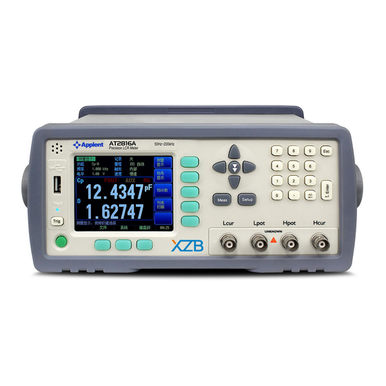
Startup Startup This chapter describes names and functions of the front panel, rear panel, and screen display and provides the basic procedures for operating AT281x. Front panel summary Rear panel summary Power On/Off Connect to Device under Test Front panel Figure 3‐1 Front panel... -
Page 18: Power On/Off
AT2818/2816A/2816B/2817A/2817/810A User's Guide Table 3‐2 Real panel description Description Frame Terminal Option Slot Power Cable Receptacle(Outlet) (to LINE) RS-232C Interface Handler Interface Power On/Off 3.3.1 Power On Press the power key at least 2 seconds. Release power key until the Trig’ed LED lit. 3.3.2 Power Off Press the power key at least 2 seconds. -
Page 19: Connect To Dut
Startup Figure 3‐3 Connect to DUT Do not apply DC voltage or current to the UNKNOWN terminals. Applying DC voltage or current may lead to device failure. Connect the measurement sample (DUT) to the test port (or the test fixture, cables, etc. connected to the test port) after the LCR meter has been completely discharged. -
Page 20: Meas] Key
AT2818/2816A/2816B/2817A/2817/810A User's Guide [Meas] Key This section includes the following information: MEAS DISPLAY page BIN No. page BIN COUNT page [Not available in AT2817] LIST SWEEP page [Not available in AT2817] <MEAS DISPLAY> Page When press the [Meas] key, the <MEAS DISPLAY> page appears. -
Page 21: Impedance Range [Range]
[Meas] Key Z-r Z-d Monitor parameters Table 4‐2 Monitor parameters r d Δ Δ% Measurement and Monitor parameter descriptions Parameter Description Capacitance value measured using the series equivalent circuit model Capacitance value measured using the parallel equivalent circuit model Inductance value measured using the series equivalent circuit model Inductance value measured using the parallel equivalent circuit model Equivalent series resistance measured using the series equivalent circuit model (ESR) -
Page 22: Test Frequency [Freq]
AT2818/2816A/2816B/2817A/2817/810A User's Guide Table 4‐3 Impedance range mode Mode Function overview Advantage Disadvantage Auto AT281x sets the optimum You don’t need to The measurement range impedance range select range. time is longer due impedance of the DUT to the ranging time Hold Measurement... -
Page 23: Table 4-5 At2818 Frequency Range And Test Frequency Point
When data is entered with the numeric keys, the soft keys change to unit labels (Hz, kHz) Soft key Function INCR ++ Refer to Table 4-8 AT2818’s Test Frequency that can be set using INCR++/DECR-- and Table 4-9 AT2816X’s Test DECR --... -
Page 24: Trigger Mode [Trig]
AT2818/2816A/2816B/2817A/2817/810A User's Guide DECR - Table 4‐8 AT2818’s Test Frequency that can be set using INCR++/DECR‐‐ INCR++/DECR-- 10Hz 50Hz 60Hz 100Hz 120Hz 1kHz 10kHz 20kHz 40kHz 50kHz 100kHz 200kHz 250kHz 300kHz Table 4‐9 AT2816X’s Test Frequency that can be set using INCR++/DECR‐‐ INCR++/DECR-- 50Hz 60Hz 100Hz 120Hz 1kHz 10kHz 20kHz 40kHz 50kHz 100kHz 200kHz Table 4‐10 AT2818’s Test Frequency that can be set using INCR+/DECR‐ INCR+/DECR- (Hz) 1.2k... -
Page 25: Test Signal Voltage Level [Level]
Function 0.1V 0.3V 1.0V Table 4-15Table 4-8 AT2818’s Test Frequency that can be set using INCR++/DECR-- (*Note: These two items are not available in AT2817) INCR + Refer to Table 4-16 (*Note: These two items are not available in AT2817) -
Page 26: Measurement Speed [Speed]
AT2818/2816A/2816B/2817A/2817/810A User's Guide 0.3V 1.0V Table 4‐15 Test voltage Level that can be set with INCR++/DECR‐‐ INCR++/DECR-- (V) 0.01 0.10 0.30 0.50 1.00 1.50 2.00 Table 4‐16 Test voltage Level that can be set with INCR+/DECR‐ INCR+/INCR- (V) 0.01 4.1.6 Measurement Speed [SPEED] SLOW, MED 1, MED 2 and FAST can be selected for AT281x. SLOW mode will result in more stable and accurate measurement result. -
Page 27: Comparator Function On/Off
[Meas] Key be set from <MEAS DISPLAY> page. Comparator function ON/OFF [COMP] Auxiliary bin ON/OFF [AUX] 4.2.1 Comparator Function ON/OFF AT281x’s built-in comparator can sort devices into a maximum of 10 bins (BIN1 to BIN9 and OUT) using a maximum of nine pairs of primary parameter limits and one pair of secondary parameter limits. -
Page 28: Auxiliary Bin [Aux]
<BIN COUNT> page 4.3.1 Counter Function [COUNT] The AT2818, AT2816X, AT2817A are capable of counting bins. The number of devices sorted into each bin is counted while unit sorts the devices into appropriate bins using the comparator function. The maximum count is 999999, the counting operation stops and the overflow message “------”... -
Page 29:
[Meas] Key COUNT ON COUNT OFF RESET COUNT The counter is reset when this key pressed. <LIST SWEEP DISPLAY> Page *Not available in AT2817 The <LIST SWEEP DISPLAY> will display when you press the [Meas] key and [LIST SWEEP] soft key. Figure 4‐5 <LIST SWEEP DISPLAY> page On the <LIST SWEEP DISPLAY> page, the sweep points are swept and the measurement results are compared to the limits.- Page
- Page 30 AT2818/2816A/2816B/2817A/2817/810A User's Guide...
-
Page 31: Setup] Key
[Setup] Key [Setup] Key This section includes the following information: MEAS SETUP page CORRECTION page LIMIT TABLE page LIST SETUP page [Not available in AT2817] Every time or everywhere you can press the [Setup] key to open the <MEAS SETUP> page. -
Page 32: Source Output Impedance [Src Res]
AT2818/2816A/2816B/2817A/2817/810A User's Guide NOTE: *1. This six setting can be set in <MEAS DISPLAY> page and <BIN No. DISPLAY> page. Please refer Sector 4.1<MEAS DISPLAY> Page to set. 5.1.1 Source Output Impedance [SRC RES] The Source output impedance can be set to 30, 50 or 100. -
Page 33: Monitor 1 And Monitor 2 [Mon 1][Mon 2]
[Setup] Key Auto LCZ Function cannot judge complex components, please do not rely entirely on NOTE this function to measure. To set up the Auto LCZ Function Step 1. Press the [Setup] key Step 2. Use the cursor key to select [BIAS] field Step 3. -
Page 34: Open Correction [Open]
AT2818/2816A/2816B/2817A/2817/810A User's Guide In this page, the OPEN/SHORT/LOAD correction for correcting the stray admittance and residual impedances can be performed. The correction function has two kinds of correction methods. In one method the open and short correction can be performed at all of the frequency points using the interpolation method, and in the other method the open, short, and load correction can be performed at the frequency points you specify. -
Page 35: Short Correction [Short]
[Setup] Key Step 1. Press the [Setup] key Step 3. Press the [CORRECTION] soft key. Step 3. Use the cursor key to select [OPEN] field Soft key Function Enables open correction. Disables open correction. MEAS OPEN Starts open correction. Step 4. Press [MEAS OPEN] soft key, a dialog message display “Connect the UNKNOWN terminal with no DUT”. -
Page 36: Frequency 1, 2, 3 Correction [Freq 1] [Freq 2] [Freq3]
AT2818/2816A/2816B/2817A/2817/810A User's Guide Step 7. Press the ON key to enable short correction in successive measurements. 5.2.3 Frequency 1, 2, 3 Correction [FREQ 1] [FREQ 2] [FREQ3] Correction based on specified frequency points involves performing open/short/load correction at user-specified frequency points. There are 3 frequency points you can specify. -
Page 37: Limit Table Setup> Page
This page allows you to configure the AT281x’s built-in comparator. AT2818/AT2816X/AT2817A’s built-in comparator can sort DUTs into a maximum 10 levels (BIN1 through BIN9 and OUT) using up to nine sets of primary parameter limits along with one set of secondary parameter limits. -
Page 38: Comparator Function On/Off
AT2818/2816A/2816B/2817A/2817/810A User's Guide Figure 5‐5 <LIMIT TABLE SETUP> Page 5.3.1 Comparator Function ON/OFF AT281x’s built-in comparator can sort devices into a maximum of 10 bins (BIN1 to BIN9 and OUT) using a maximum of nine pairs of primary parameter limits and one pair of secondary parameter limits. -
Page 39: Auxiliary Bin [Aux]
[Setup] Key Step 1. Press the [Setup] key Step 2. Press the [LIMIT TABLE] soft key Step 3. Use the cursor key to select [COMP] field Step 4. Use the soft keys to turn on/off the comparator. Soft key Function 5.3.2 Auxiliary Bin [AUX] After AUX turned on, DUTs that do not fall within the primary parameter limit values... -
Page 40: Example Of Sorting In Tolerance Mode
AT2818/2816A/2816B/2817A/2817/810A User's Guide ● Includes the point ○ Excludes the point Absolute value () = UNKNOWN value – nominal value Deviation percentages (%) = Absolute value () / nominal value × 100% Figure 5‐8 Example of sorting in tolerance mode ● Includes the point ○... -
Page 41: Nominal Value For Tolerance Mode
Buzzer sound high Buzzer sound low 5.3.7 Total Number of Bins [#‐BINS] AT2817A, AT2816x and AT2818 specify nine bins (1-BINS to 9-BINS). AT2817 specifies three bins (1-BINS to 3-BINS). To choose total number of the bins Step 1. Press the [Setup] key Step 2. Press the [LIMIT TABLE] soft key Step 3. -
Page 42: Lower And Upper Limits
*Not available in AT2817 Press the [Setup] key and press [LIST SETUP] soft key to open the <LIST SWEEP SETUP> page. The list sweep feature of AT2817A, AT2816X and AT2818 can perform automatic sweep measurement by sweeping the frequency, signal level through a maximum 10 sweep points. -
Page 43: Sweep Trigger Mode [Trig]
[Setup] Key 5.4.1 Sweep Trigger Mode [TRIG] Figure 5‐11 Sweep trigger mode Trig Mode Function Internal Trigger. All ten sweep points are swept continuous. Manual Trigger. Each time the instrument is triggered by [Trig] key, the sweep points are swept one by one. External Trigger. Each time the instrument is triggered by the handler trigger pin, the sweep points are swept one by one. -
Page 44: Sweep Point And Limit Modes
Uses voltage as the list sweep parameter 5.4.3 Sweep Point and Limit Modes AT2817, AT2816X and AT2818’s List sweep measurement feature supports up to 10 sweep points as well as measurement limit values. Each of sweep point can be turned on or off. To configure the sweep points Step 1. -
Page 45: System Configurations
System Configurations System Configurations This section includes the following information: SYSTEM INFO page SYSTEM CONFIG page SYSTEM SERVICE page <SYSTEM CONFIG> Page When press the [Meas] or [Setup] key followed by [SYSTEM] bottom soft key, the <SYSTEM CONFIG> page appears. Following information can be configured in the <SYSTEM CONFIG>... -
Page 46: Setting The System Date And Time
AT2818/2816A/2816B/2817A/2817/810A User's Guide 6.1.2 Setting the system date and time AT281x features a built-in 24-hour clock. To change the date Step 1. Press the [Meas] or [Setup] key Step 2. Press the [SYSTEM] bottom soft key. Step 3. Use the cursor key to select date field Step 4. -
Page 47: Beep Feature
System Configurations Step 3. Use the cursor key to select [ADMIN] field. When the account field is [USER], you should change to [ADMIN]. Step 4. Use the soft keys to change password or delete password. Soft key Function CHANGE PASSWORD Input password(less than 9 numbers). DELETE PASSWORD The password will be removed. -
Page 48: System Info> Page
AT2818/2816A/2816B/2817A/2817/810A User's Guide Step 3. Use the cursor key to select [BAUD] field Step 4. Use the soft keys to select baud rate. Soft key Function 1200 9600 38400 57600 115200 Recommend, system default. <SYSTEM INFO> Page When press the [Meas] or [Setup] key followed by [SYSTEM] bottom soft key, and press [SYSTEM INFO] soft key, the <SYSTEM INFO>... -
Page 49: File Operation
File Operation File Operation This chapter provides information on the file operation of the AT281x. You can save up to 10 files into the internal non-volatile memory. <CATALOG> Page When press the [Meas] or [Setup] key followed by [FILE] bottom soft key, the <CATALOG>... -
Page 50: Auto Save Data To Last File [Auto Save]
AT2818/2816A/2816B/2817A/2817/810A User's Guide Step 3. Use the cursor key to select [AUTO RECALL] field Step 4. Use the soft keys to select. Soft key Function LAST FILE Last used file will be recalled at next startup. FILE 0 File 0 will be recalled at next instrument startup. -
Page 51: Handler Interface
Handler Interface Handler Interface This chapter provides information of AT281x’s built-in handler interface. Include: Pin Assignment Circuit Diagram Timing Chart The AT281x’s built-in handler interface outputs signals that indicate the end of a measurement cycle, the result of bin sorting by the comparator. In addition, the instrument accepts input of external trigger. -
Page 52: Power Rating
AT2818/2816A/2816B/2817A/2817/810A User's Guide The power of built-in 5k pull-up resistance of the output signals. “Primary parameter beyond upper limit” signal. /PHI Output This signal is output when the primary parameter ha exceeded the upper limit for bins 1 to 9. -
Page 53: Electrical Characteristics
Handler Interface Electrical Characteristics 8.3.1 Input Signal: Each input signal is connected to the LED (cathode side) of the photo-coupler. The LED (anode side) is connected to the pull-up power supply voltage. 8.3.2 Output Signal: Each output signal is outputted via an open collector by using a photo-coupler. The voltage of each output is obtained by connecting pull-up resistors, inside or outside of the AT281x. -
Page 54: Timing Chart
AT2818/2816A/2816B/2817A/2817/810A User's Guide EXT.DCV INPUT Figure 8‐4 Typical Circuit Diagram of Handler Interface Output signals. EXT.DCV 4.99k OUTPUT GN D Timing Chart Figure 8‐5 Timing chart next trig ger TR I G m ea sur em e nt ci r cl e I D X... -
Page 55: Table 8-2 Timing
Handler Interface Table 8‐2 Timing Time Description 100Hz 180ms 120Hz 160ms FAST 1kHz 67ms 10kHz 67ms 100kHz 67ms 100Hz 260ms 120Hz 225ms One Measurement Circle MED2 1kHz 235ms 10kHz 235ms 100kHz 235ms 100Hz 500ms 120Hz 425ms SLOW 1kHz 580ms 10kHz 580ms 100kHz 580ms Trigger pulse width... -
Page 56: Examples
AT2818/2816A/2816B/2817A/2817/810A User's Guide Examples This chapter covers basic measurement procedures as well as basic L, C, and R measurement theory. It also offers various measurement hints. After the descriptions of basic measurement procedures, practical measurement examples are shown using AT281x. -
Page 57: Example
Examples Example This paragraph describes a practical example of measuring a ceramic capacitor. The basic procedure flow to perform this measurement is the same as the Basic Measurement Procedure described previously. In this example, a ceramic capacitor is measured under the following conditions. Sample (DUT) Ceramic capacitor Measurement Conditions: •... -
Page 58: Measurement Results
AT2818/2816A/2816B/2817A/2817/810A User's Guide 7. Press [MEAS SHORT] soft key and [OK] soft key. Wait until the message “Correction finished” displays. 8. Press [ON] soft key if SHORT field is OFF. Step 5. Connect DUT to the test fixture as shown like this: Step 6. -
Page 59: Remote Control
Remote Control Remote Control This chapter provides the following information to remotely control the AT281x via the RS-232C or USB interface. About RS-232C About USB Interface Select Baud Rate. About SCPI AT281x can use the RS-232 interface or USB interface to communicate with the computer to complete all the instrument functions. -
Page 60: To Select Baud Rate
AT2818/2816A/2816B/2817A/2817/810A User's Guide 10.3 To Select Baud Rate Before you can control the AT281x by issuing RS-232 commands from built-in RS-232 controller connected via its DB-9 connector, you have to configure the RS-232 baud rate. The AT281x’s built-in RS-232 interface uses the SCPI language. - Page 61 Remote Control 4. Select “Search for the best driver in these locations” and browse a location (“E:\FTDI driver” in figure below) by clicking the browse button. Once the file path has been selected, click next to proceed. 5. If Windows XP is configured to warn when unsigned (non-WHQL certified) drivers are about to be installed will be displayed unless installing a Microsoft WHQL certified driver.
-
Page 62: Usb Serial Port
AT2818/2816A/2816B/2817A/2817/810A User's Guide 7. Completing the Found New Hardware Wizard. Click “Finish” to complete the installation for the first port of the device. 8. The “Found New hardware Wizard will continue by installing the USB-Serial Converter driver for the second port of the device. -
Page 63: Installing At281X Serial_Port_Debug Software
Remote Control 10.4.2 Installing AT281X Serial_Port_Debug Software 1. Run “AT281X_Serial_Port_Debug\Setup.exe” Click “Next” to continue. 2. After finishing the Installation, Run “Serial_Port_Debug” on your desktop. -
Page 64: Scpi Language
AT2818/2816A/2816B/2817A/2817/810A User's Guide Please select Port that displayed in “Device Manager” (Refer to Figure 10-2 USB Serial Port) and select the same baud rate as AT281X’s <SYSTEM CONFIG> BAUD Item. 3. Press “OPEN COM” to Open USB-Serial connection. 4. Input a command (Refer to 11. Command Reference) and press “Send”. - Page 65 Remote Control RS-232 interfaces. NOTE: AT281x ONLY supports the SCPI Language.
-
Page 66: Command Reference
AT2818/2816A/2816B/2817A/2817/810A User's Guide Command Reference This chapter contains reference information on programming AT281x with the SCPI commands. This chapter provides descriptions of all the AT281x's available RS-232 commands which correspond to Standard Commands for Programmable Instruments (SCPI) command sets, listed in functional subsystem order. - Page 67 Command Reference function :imp? :mon1 :imp :type {…} rang? Example: function:imp:type Cp-D function Subsystem Command Level 2 type Level 3 Cp-D Parameter The basic rules of the command tree are as follows. Letter case (upper and lower) is ignored. For example, FUNCTION: IMPEDANCE function:impedance...
-
Page 68: Header And Parameters
AT2818/2816A/2816B/2817A/2817/810A User's Guide command line. For example, func:rang 8;*IDN?;auto on Command abbreviations: Every command and character parameter has at least two forms, a short form and a long form. In some cases they will be the same. The short form is obtained using the following rules. -
Page 69: Command Reference
Command Reference (b) NR2 fix float: For example, 1.23,+1.23,-1.23 (c) NR3 floating point: For example, 1.23e3, 5.67e-3, 123k, 1.23M, 2.34G, The available range for numeric data is 9.9E37. When numeric data is used as a parameter, the suffix multiplier mnemonics and suffix units (The suffix multiplier must be used with the suffix unit.) can be used for some commands as follows. -
Page 70: Display Subsystem
AT2818/2816A/2816B/2817A/2817/810A User's Guide 2. Command Tree (Subsystem command only) 3. Compound Command Name 4. Command Description 5. Command Syntax 6. Example Using the Above Command Syntax 7. Query Syntax 8. Query Response 9. Example Using the Above Query Syntax 10. Constraints 11.6... -
Page 71: Disp:line
Command Reference Example SEND> DISP:PAGE SYST //Set to the SYSEMT CONFIG <NL> Query Syntax DISP:PAGE? Query Response <page name> <NL> Example SEND> DISP:PAGE? <NL> RET> SYST <NL> 11.6.2 DISP:LINE The :LINE command enters an arbitrary comment line of up to 30 ASCII characters in the comment field. -
Page 72: Function:impedance:range
AT2818/2816A/2816B/2817A/2817/810A User's Guide Cs-Rs, Cs-D, Cp-Rp, Cp-D, Lp-Rp, Lp-Q, Ls-Rs, Ls-Q, R-Q, R-X, Z-r, Z-d (: ASCII Hex 0xE9) Example SEND> FUNC Cp-D //Set measurement function to Cp-D <NL> Query Syntax FUNC[:IMPedance][:TYPE]? Query Response <function> Example SEND> FUNC? <NL> RET>... -
Page 73: Frequency Subsystem
Command Reference IAC} Please refer to Page 33 Sector 5.1.5 Monitor 1 and Monitor 2 [MON 1][MON 2]. Example SEND> FUNC:MON1 Z <NL> Query Syntax FUNC:MON1? FUNC:MON2? Query Response {off, Z, D, Q, THR, THD, R, X, G, B, Y, ABS, PER VAC, IAC} Example SEND>... -
Page 74: Voltage:level
AT2818/2816A/2816B/2817A/2817/810A User's Guide 11.9.1 VOLTage:LEVel The VOLTage:LEVel command sets the oscillator’s output voltage level. Command Syntax VOLTage:LEVel {<value>,MIN,MAX} Parameter Where, <value> is the numeric data (NR1, NR2 or NR3). Please refer to Page 25 (Section 4.1.5) Sets to the minimum value Sets to the maximum value Example SEND>... -
Page 75: Aperture:rate
Command Reference Command Syntax APERture {SLOW,MED1,MED2,FAST} APERture <value> Parameter Where, SLOW Set test speed to slow MED1 Set test speed to medium (level 1) MED2 Set test speed to medium (level 2) FAST Set test speed to fast <value> NR1(0 to 256): Averaging rate (0=OFF=1) Example SEND>... -
Page 76: Fetch[:Impedance]
AT2818/2816A/2816B/2817A/2817/810A User's Guide 11.11.1 FETCh[:IMPedance]? The FETCh[:IMPedance]? query sets the latest measurement data of the primary , secondary parameters and comparator result into the output buffer. Query Syntax FETCh[:IMPedance]? Query Response <NR3:primary value>,<NR3:secondary value>,<comparator result> Example SEND> FETC? <NL> RET>... -
Page 77: Comparator:state
Command Reference 11.12.1 COMParator:STATe The COMParator:STATe command sets the comparator function to ON or OFF. Command Syntax COMParator:STATe {ON,OFF,1,0} Parameter Where, ON or 1 Sets the comparator to ON OFF or 0 Sets the comparator to OFF Example SEND> COMP:STAT OFF <NL>... -
Page 78: Comparator:aux
AT2818/2816A/2816B/2817A/2817/810A User's Guide 11.12.3 COMParator:AUX The COMParator:AUX command sets the auxiliary BIN counting function of the comparator to ON or OFF. Command Syntax COMParator:AUX {ON,OFF,1,0} Parameter Where,{ON,OFF,1,0} is: ON or 1 Set the AUX BIN to ON OFF or 0 Set the AUX BIN to OFF Example SEND>... -
Page 79: Comparator:slim
Command Reference high limit NR1,NR2 or NR3: high limit value Example SEND> COMP:TOL:BIN 1,100P,200P <NL> SEND> COMP:TOL:BIN 2,200E-6,300E-6 <NL> Query Syntax COMParator:TOLerance:BIN? <n> Parameter Where,<n> is: NR1 (1 to 9): Bin number Query Response <NR3:low limit>,<NR3:high limit> Example SEND> COMP:TOL:BIN? 2 <NL>... -
Page 80: List:stat
AT2818/2816A/2816B/2817A/2817/810A User's Guide Parameter Where, {FREQ,LEVEL} is: FREQ Sets the sweep parameter to frequency LEVEL Sets the sweep parameter to voltage level Example SEND> LIST:PARA LEVEL <NL> Query Syntax LIST:PARAmeter? Query Response {FREQ,LEVEL} Example SEND> LIST:PARA? <NL> RET> FREQ <NL>... -
Page 81: Correction Subsystem
Command Reference 11.14 CORRection Subsystem The CORRection subsystem command group sets the correction function, including the OPEN, SHORT and LOAD correction settings. NOTE: The CORRection subsystem CANNOT work in <LIST SWEEP DISPLAY> page. Figure 11‐10 CORRection Subsystem Command Tree 11.14.1 CORRection:OPEN The CORRection:OPEN command execute all presetted OPEN correction data measurement points. -
Page 82: Correction:short
AT2818/2816A/2816B/2817A/2817/810A User's Guide OFF. Command Syntax CORRection:OPEN:STATe {ON,OFF,1,0} Parameter Where, {ON,OFF,1,0} is: ON, 1 When the function is ON OFF,0 When the function is OFF Example SEND> CORR:OPEN:STATe ON <NL> RET> open <NL> Query Syntax CORRection:OPEN:STATe? Query Response {on,off} Example SEND> CORR:OPEN:STATe? <NL>... -
Page 83: Correction:spot:stat
Command Reference 11.14.4 CORRection:SPOT:STAT The CORRection:SPOT:STATe command sets the LOAD correction function to ON or OFF. Command Syntax CORRection:LOAD:STATe {ON,OFF,1,0} Parameter Where, {ON,OFF,1,0} is: ON, 1 When the function is ON OFF,0 When the function is OFF Example SEND> CORR:LOAD:STATe ON <NL>... -
Page 84: Trigger Subsystem
AT2818/2816A/2816B/2817A/2817/810A User's Guide Example SEND> CORR:SPOT:LOAD 1 <NL> 11.14.8.1 CORRection:SPOT:LOAD:STANdard This command sets the reference values of the standard at the specified frequency point(FREQ1,FREQ2 or FREQ3). Command Syntax CORRection:SPOT:LOAD:STANdard <n>,<REF.A>,<REF.B> Parameter Where, <n>,<REF.A>,<REF.B> is: NR1(1,2 or 3):Spot number REF.A NR1,NR2 or NR3:Primary parameter’s reference value of the standard. -
Page 85: Bias Subsystem
Command Reference BUS Trigger Mode Example SEND> TRIG:SOUR BUS <NL> Query Syntax TRIGger:SOURce? Query Response {INT,MAN,EXT,BUS} Example SEND> TRIG:SOUR? 1 <NL> RET> <NL> 11.16 BIAS Subsystem The BIAS subsystem command group sets the DC BIAS switch to ON or OFF, and sets the DC bias voltage value. -
Page 86: File:load
AT2818/2816A/2816B/2817A/2817/810A User's Guide Command Syntax FILE:SAVE Example SEND> FILE:SAVE <NL> The FILE:SAVE <n> command saves all user settings into specified file. Command Syntax FILE:SAVE <File No.> Parameter Where, <File No.> is: NR1 (0 to 9) Example SEND> FILE:SAVE 0 <NL>... -
Page 87: Sav
Command Reference Execute Trigger command. Command Syntax *TRG Query Response <primary value>,<secondary value>,<comparator result> Example SEND> *TRG RET> +5.566785e-11,+7.253470e-01,OUT Note This command can be used in BUS trigger mode. *TRG = TRIG;:FETC? 11.19.3 *SAV *SAV = FILE:SAVE The *SAV command saves all user settings into current used file. Command Syntax *SAV Example SEND>... -
Page 88: Specification
AT2818/2816A/2816B/2817A/2817/810A User's Guide Specification This chapter describes the specifications and supplemental performance characteristics of the AT281x: Specifications Dimension Accuracy is defined as meeting all of the following conditions. Temperature: 23℃±5℃ Humidity: 65% R.H. Zeroing: Open and Short Correction Warm up time is 30 min or more. - Page 89 100.0000Hz F 999.999Hz 0.001Hz 1.00000kHz F 9.99999kHz 0.01Hz 10.0000kHz F 20.0000kHz 0.1Hz Measurement Range AT2818 AT2816A AT2816B AT2817A Parameter Measurement Range 0.00001H ~ 9999.99H 0.00001pF ~ 9999.99mF 0.00001Ω ~ 99.9999M R、X、Z 0.01nS ~ 999.999S B、G...
- Page 90 AT2818/2816A/2816B/2817A/2817/810A User's Guide 0.0001pF ~ 9999.9mF 0.0001Ω ~ 99.999M R、X、Z 0.01nS ~ 999.99S B、G 0.0001 ~ 9.9999 0.0001 ~ 99999 θd -179.99°~179.99° θr -3.1416 ~ 3.1416 -99.999% ~ 999.99% AT810A Measurement Range Parameter Measurement Range 0.001nH ~ 9999.99H 0.001pF ~ 9999.99mF 0.00001Ω ~ 99.9999M...
-
Page 91: Dimensions
Storage temperature and humidity range: 10 ~40 ,10~90% RH ℃ ℃ Power Supply: AC 95V-260V, 48.5Hz-62.5Hz Fuse: 3A Slow-Blow Maximum rated power: 30VA Weight: 3.5kg, net 12.2 Dimensions Figure 12‐1 Dimensions @ Instruments -AT281x User’s Guild- English ©2005-2010 Applent Instruments Inc.
Need help?
Do you have a question about the AT2818 and is the answer not in the manual?
Questions and answers