Table of Contents
Advertisement
User's Guide
Rev.A4
~
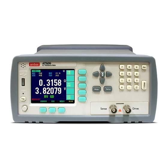
AT526
Battery Internal Resistance Meter
ACR: 0.001mΩ ~ 33.000kΩ
DCV: 0.00000V~120.000VDC
Measurement Speed: 6.8 ms
®
Applent Instruments Inc.
@
Address: Dangnan Industrial Zone,
Changzhou, Jiangsu, China (PRC)
Post Code: 213014
Tel: 0086-0519-88805550 / 89966117 / 89966227 / 89966337
Fax: 0086-0519-89966550
Sales Email:
Tech Email:
http://www.applent.com
sales@applent.com
tech@applent.com
Advertisement
Table of Contents

Related Manuals for Applent Instruments AT526


Summary of Contents for Applent Instruments AT526
- Page 1 AT526 Rev.A4 Battery Internal Resistance Meter ACR: 0.001mΩ ~ 33.000kΩ DCV: 0.00000V~120.000VDC Measurement Speed: 6.8 ms ® Applent Instruments Inc. Address: Dangnan Industrial Zone, Changzhou, Jiangsu, China (PRC) Post Code: 213014 Tel: 0086-0519-88805550 / 89966117 / 89966227 / 89966337 Fax: 0086-0519-89966550 sales@applent.com Sales Email: tech@applent.com...
-
Page 2: Certification, Limited Warranty, & Limitation Of Liability
CERTIFICATION, LIMITED WARRANTY, & LIMITATION OF LIABILITY Applent Instruments, Ltd. (shortened form Applent) certifies that this product met its published specifications at the time of shipment from the factory. Applent further certifies that its calibration measurements are traceable to the People’s Republic of China National Institute of Standards and Technology, to the extent allowed by the Institution’s calibration facility or by the calibration facilities of other International Standards Organization... -
Page 3: Table Of Contents
Contents Contents CERTIFICATION, LIMITED WARRANTY, & LIMITATION OF LIABILITY ............. 2 Contents ..................................3 Figure Contents................................5 Table Contents ................................5 1. Unpacking and Preparation ..........................6 1.1 Incoming Inspection .......................... 6 1.2 Power requirements and setting up Fuse ................... 6 1.3 ... - Page 4 AT526 User's Guide 7.2 Power Rating ........................... 25 7.3 Electrical Characteristics ......................... 25 7.3.1 Input Signal: ..........................25 7.3.2 Output Signal: .......................... 25 7.3.3 Power supply ........................... 25 7.3.4 Schematic ..........................25 8. Remote Control ..............................27 8.1 About RS-232C ..........................27 ...
- Page 5 Figure Contents Figure Contents Figure 1-1 How to remove the handle ......................8 Figure 3-1 Front panel ..........................11 Figure 3-2 Rear Panel ..........................11 Figure 3-3 Connect to DUT ........................12 Figure 7-1 Pin Assignment ........................24 Figure 7-2 Typical Circuit Diagram of Handler Interface Input signals.
-
Page 6: Unpacking And Preparation
Please use the following fuse type. UL/CSA type, Slow-Blow, 5×20-mm miniature fuse, 1A, 250 V When you need a fuse, contact your nearest Applent Instruments sales or service office. To verify and replace the fuse, remove the power cable and pull out the fuse holder. -
Page 7: Cleaning
Altitude: 0 to 2,000m Vibration: Max. 0.5 G, 5 Hz to 500 Hz Cleaning To prevent electrical shock, disconnect the AT526 power cable from the receptacle before cleaning. Use a dry cloth or a cloth slightly dipped in water to clean the casing. - Page 8 AT526 User's Guide Figure 1‐1 How to remove the handle 1 Retracted 3 Carrying Position 2 Extended Remove Handle(Lift the handle perpendicular to the unit while pulling it in the direction of 1.)...
-
Page 9: Overview
UPS battery while UPS working online. AT526 is equipped with RS232 interface to apply to remote control, data acquisition and analysis. AT526 is also equipped with USB-Disk interface, and you can store the test values into your USB Disk over 500 sets. Main Specifications and Features ... -
Page 10: Main Functions
AT526 User's Guide Main Functions 2.3.1 Correction Short-circuit Clear Zero correction for all ranges. 2.3.2 Comparator (Sorting Function) Set up sorting function to do GD/NG sorting. Comparator Methods: Absolute value of tolerance ±TOL sorting Percentage tolerance TOL sorting Sequence comparison sorting Beep Feature: Beep: OFF/GD/NG 2.3.3... -
Page 11: Startup
Startup Startup This chapter describes names and functions of the front panel, rear panel, and screen display and provides the basic procedures for operating AT526. Front panel summary Rear panel summary Power On/Off Connect to Device under Test Front panel Figure 3‐1... -
Page 12: Power On/Off
Power On/Off 3.3.1 Line Power Connection Power ON. Power OFF. Warm‐up Time AT526 is ready to be used as soon as the power-up sequence has completed. However, to achieve the accuracy rating, warm up the instrument for 30 minutes. Connect to Device under Test (DUT) Figure 3‐3 Connect to DUT Warning: No putting current source, voltage source directly access to test side. Energy storage device access to testing after discharging. -
Page 13:
Soft-key VIEW DATA – To Enter [VIEWDATA] page Soft-key SAVE DATA – To Store measurement result into internal flash disk. Figure 4‐1 <MEAS DISPLAY>Page (Ultra-Fast Speed Mode) 4.1.1 [TRIGGER] SCPI Command: TRIGger:SOURce {INT,MAN,EXT,BUS} SCPI Query Command: TRIGger:SOURce? AT526 supports four trigger modes: INT (internal), EXT (external), MAN (manual) and...Key -
Page 14: Range]
[RANGE] SCPI Command: FUNCtion:RANGe {<range number>,min,max} SCPI Command: FUNCtion:RANGe:MODE {AUTO,HOLD,NOMinal} SCPI Query Command: FUNCtion:RANGe? SCPI Query Command: FUNCtion:RANGe:MODE? AT526 has three resistance range modes and two voltage range. Resistance Ranges: Auto range, Manual range and Nominal range Table 4‐2 Resistance Range Mode Range Description... -
Page 15: Measurement Speed [Speed]
Range Name Measurement Range 120V 12.0V~120V 0V~12.2V The DC voltage measurement range cannot be selected. AT526 always uses automatic range mode under SLOW, MED and FAST speed mode and use the maximum range under ULTRA speed mode. 4.1.3 Measurement Speed [SPEED] SCPI Command: FUNCtion:RATE {SLOW,MED,FAST,ULTRA} SCPI Query Command: FUNCtion:RATE? SLOW, MED, FAST and ULTRA speed mode can be selected for AT526. -
Page 16: Icons On
The saved data can be reviewed on <VIEW DATA> page by pressing [VIEW DATA] soft-key. <VIEW DATA> page The measurement result can be stored in AT526’s internal nonvolatile memory by press the [SAVE DATA] soft-key in <MEAS DISPLAY> page. Over 500 sets data can be saved. -
Page 17: Setup] Key
[SETUP] Key [SETUP] Key This chapter describes: <STEUP> page Short-circuit Clear Zero < SETUP> page Press [Setup] key to enter <SETUP>page. In <SETUP> page, the Instrument does not display measurement result and comparator result, testing is not in progress. The <SETUP> page includes following setup: ... -
Page 18: Comparator Mode [R-Comp],[V-Comp]
AT526 User's Guide After correction, the value will be saved into internal flash disk. It is necessary to do short-circuit clear zero correction. When replace the test fixture or test cables, please do short –circle clear zero. How to connect the test clips before executing short-circle clear. - Page 19 [SETUP] Key The high limited value should be greater than low nominal value. When in SEQ Mode, please input the direct value of resistance or voltage. When in ABS Mode, please input the absolute value of resistance or voltage. When in PER% Mode, please input the relative value of resistance or voltage in %. ...
-
Page 20:
AT526 User's Guide <SYSTEM CONFIG> page This chapter describes: SYSTEM CONFIG SYSTEM INFORMATION SYSTEM SERVICE <SYSTEM CONFIG> page Press [SYSTEM] bottom soft-key to enter <SYSTEM CONFIG> page. LANGUAGE – Choose English or Chinese Language DATE/TIME ACCOUNT BEEP Feature ...Page -
Page 21: Account], [Password]
<SYSTEM CONFIG> page ENGLISH 6.1.2 [ACCOUNT], [PASSWORD] ADMIN – All settings are available and can be saved. USER – All settings are available but cannot be saved. Procedure to set up account: Step 1 Press [Meas] or [Setup] key to enter main page Step 2 Press bottom soft-key [SYSTEM] to enter <SYSTEM CONFIG>... -
Page 22: Rs232 [Baud] Rate
AT526 User's Guide 6.1.4 RS232 [BAUD] rate Before you can control the AT526 by issuing RS-232 commands from built-in RS-232 controller connected via its DB-9 connector, you have to configure the RS-232 baud rate. The AT526’s built-in RS-232 interface uses the SCPI language. -
Page 23:
Step 3. Use the cursor key to select [RESULT SEND] field Step 4. Use the soft keys to turn ON. FETCH Acquire the test result by sending “FETCH?” command only. AUTO AT526 return the result every EOM <SYSTEM INFORMATION> There is no configurable option in the <SYSTEM INFO> page. Figure 6‐2 <SYSTEM INFORMATION>page ... -
Page 24: Handler Interface
In addition, the instrument accepts input of external trigger. You can use these signals to easily integrate the AT526 with a component handler or system controller. This means that you can fully automate such tasks as component inspection, component sorting, and processing of quality management data for higher manufacturing efficiency. -
Page 25: Power Rating
Handler Interface external VCC 33-34 Internal VCC Power Internal VCC (5VDC 1A) 35-36 External VCC Power External VCC (3.3V~35V) Power Rating Input/output device Logic Electrical requirements OUTPUT Corrector with Negative logic 35VDC pull-up resistance 50mADC max INPUT Rising-edge 50mADC max EXT.DCV DC voltage input 35VDC max INT.DCV... - Page 26 AT526 User's Guide TO PLC IO or Si gnal Rel ay R243 Internal...
-
Page 27: Remote Control
Remote Control Remote Control This chapter provides the following information to remotely control the AT526 via the RS-232C or USB interface. About RS-232C About USB Interface Select Baud Rate. About SCPI AT526 can use the RS-232 interface or USB interface to communicate with the computer to complete all the instrument functions. -
Page 28: About Usb-Serial Interface (Option)
AT526 User's Guide About USB‐Serial Interface (Option) The USB-Serial Interface allows you to connect AT526 to a USB port on your PC. NOTE: Please install the USB-Serial driver before using USB-Serial Interface. The Applent USB-Serial interface model is ATN2. Figure 8‐2 USB‐Serial Interface ATN2 To Select Baud Rate Before you can control the AT526 by issuing RS-232 commands from built-in RS-232 controller connected via its DB-9 connector, you have to configure the RS-232 baud rate. - Page 29 Remote Control RS-232 interfaces. NOTE: AT526 ONLY supports the SCPI Language.
-
Page 30: Command Reference
The common commands are defined in IEEE std. 488.2-1987, and these commands are common for all devices. The SCPI commands are used to control all of the AT526's functions. The SCPI commands are tree structured three levels deep. The highest level commands are called the subsystem commands in this manual. -
Page 31: Header And Parameters
For example, root:com3:com5 ppp; : root:com1 ppp The AT526 accepts the three forms of the same SCPI commands: all upper case, all lower case, and mixed upper and lower case. Header and Parameters The commands consist of a command header and parameters. -
Page 32: Command Reference
AT526 User's Guide Parameters may be of two types as follows. (A) Character Data and String Data Character data consists of ASCII characters. The abbreviation rules are the same as the rules for command headers. (B) Numeric Data (a) <integer>: For example, 1,+123,-123 (b) <float>: For example, 1.23e3, 5.67e-3, 123k, 1.23M, 2.34G, 1.234... -
Page 33: Disp:line
Command Reference SETUP [or SETU] Sets display page to SETUP SYSTem [or SYST] Sets display page to SYSTEM CONFIG SYSTEMINFO [or SINF] Sets display page to SYSTEM INFORMATION Example SEND> DISP:PAGE SYST //Set to the SYSEMT CONFIG <NL> Query Syntax DISP:PAGE? Query Response <page name>... -
Page 34: Comparator Subsystem
AT526 User's Guide RET> ULTR <NL> COMParator Subsystem The COMParator subsystem command group sets the comparator function, including its ON/OFF setting, limit mode, and limit values. Figure 9‐4 COMParator Subsystem Command Tree COMParator :BEEP {OFF,GD,NG} :RMODe {OFF,SEQ,PER,ABS} :VMODe {OFF,SEQ,PER,ABS} :TOLerance RNOMinal <float> VNOMinal <float> RLIMIT(RLMT) <LOWER,UPPER>... -
Page 35: Comparator:tolerence:rlimit
Command Reference SEND> COMP:TOL:RNOM 1E-6 <NL> Query Syntax COMParator:TOLerence:RNOMinal? Query Response <scifloat> Example SEND> COMP:TOL:RNOM? <NL> RET> +1.00000e-03 <NL> 9.8.5 COMParator:TOLerence:RLiMiT The COMParator:TOLerence:RLiMiT command sets resistance lower/upper limit values. Command Syntax COMParator:TOLerence:RLiMiT <lower>,<upper limit> Parameter Where,<lower>,<upper> is: lower <float> lower limit value upper <float>... -
Page 36: Trigger:source
AT526 User's Guide 9.9.2 TRIGger:SOURce The TRIGger:SOURce command sets the trigger mode. Command Syntax TRIGger:SOURce {INT,MAN,EXT,BUS} Parameter Where, {INT,MAN,EXT,BUS} is Internal Trigger Mode Manual Trigger Mode External Trigger Mode Remote Trigger Mode Example SEND> TRIG:SOUR BUS <NL> Query Syntax TRIGger:SOURce? Query Response {INT,MAN,EXT,BUS} Example SEND>... -
Page 37: System Subsystem
Command Reference 9.12 SYSTem subsystem Figure 9‐8 SYSTem commad tree SYSTem :SENDmode {FETCH,AUTO} 9.12.1 SYSTem:SENDmode SYST:SEND command sets the RS-232 Result Send Mode. Please refer to Page.22 Section 0 If you use Applent Software, please make sure that the [SHAKE HAND] was NOTE: turned OFF. RS-232 Result Send Mode [RESULT SEND] Command Syntax SYSTe m:SENDmode {FETCH,AUTO}... -
Page 38: Specification
AT526 User's Guide Specification This chapter describes: Basic Specifications Dimensions 10.1 General Specifications Accuracy is defined as meeting all of the following conditions. Temperature: 23℃±5℃ Humidity: 65% R.H. Correction: Short-circuit Clear Zero Warming Time: >60min ... -
Page 39: Ac Resistance Range
Specification 10.3 AC Resistance Range RANGE Max Reading Resolution ULTRA FAST SLOW Test Current 30mΩ 33.000mΩ 1μΩ 0.5% ± 20 0.3% ± 10 0.2% ± 10 0.2% ± 5 150mA 300mΩ 330.00mΩ 10μΩ 0.5% ± 20 0.3% ± 10 0.2% ± 10 0.2% ±... -
Page 40: Dimensions
AT526 User's Guide Storage temperature and humidity range: 10 ~40 , ℃ 10~90% RH ℃ Power Supply: AC 110V/220V, 48.5Hz-62.5Hz Fuse: 1A Slow-Blow Maximum rated power: 15VA Weight: 3.5kg, net 10.7 Dimensions Figure 10‐1 Dimensions -AT526 User’s Guide- English ©2005-2014 Applent Instruments Ltd.
Need help?
Do you have a question about the AT526 and is the answer not in the manual?
Questions and answers