Sign In
Upload
Manuals
Brands
Brooks Manuals
Measuring Instruments
5850 S
Brooks 5850 S Manuals
Manuals and User Guides for Brooks 5850 S. We have
2
Brooks 5850 S manuals available for free PDF download: Installation And Operation Manual
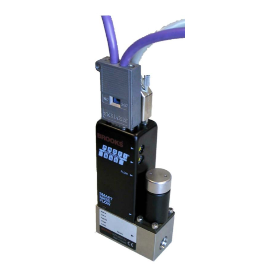
Brooks 5850 S Installation And Operation Manual (50 pages)
Profibus-DP Interface for use with Brooks Smart Mass Flow Meters
Brand:
Brooks
| Category:
Measuring Instruments
| Size: 1.46 MB
Table of Contents
Table of Contents
4
1 Introduction
6
How to Use this Manual
6
Related Documents
6
Definition of Terms
7
Terminology
7
Number Representations and Formats
8
2 Product Overview
9
General
9
Receipt of Equipment
9
Recommended Storage Practice
10
Return Shipment
10
Gas Connectionsl
10
The Brooks Smart Mass Flow Products
11
Table 2-1: Brooks Smart Mass Flow Meters and Controllers
11
Profibus on the Smart TMF Series
12
3 Installation
14
Electrical Interfacing
14
General
14
Main Connector
14
Table 3-1: Smart TMF Main Connector Pin Layout
15
Figure 3-1: Smart TMF Main 15-Pin Male Sub-D Connector - Pin Numbering
15
Additional Profibus Connector (5800 Series)
16
Table 3-2: Smart TMF Profibus-DP Network Connector Pin Layout
16
Figure 3-2: Profibus 9-Pin Female Sub-D Connector - Pin Numbering
16
Main Connector (MF Series)
17
Figure 3-3: MF Profibus Main Power Connection
17
Profibus Connector (MF Series)
18
Station Address Selection
18
Figure 3-4: Pinnumbering
18
Figure 3-5: Smart Mass Flow Meter/Controller - Outlet View
18
Zero Pushbutton
19
Supported Baud Rates
19
Profibus Network Wiring
20
Profibus Network Wiring Requirements
20
Supported Baud Rate Values
20
Table 3-4: Profibus Cable Parameters
20
Figure 3-6: Profibus Line Termination Configuration
21
Figure 3-7: Recommended TEE and Terminator Resistor
21
Line Termination Requirements
21
Special Requirements for High-Speed Communication
21
Figure 3-8: High-Speed Communication Inductors
22
4 Slave Configuration
23
Introduction
23
Illustration of the Profibus-DP Communication Procedure
23
Parameterization of the Salve (MFC)
23
Configuration of the Slave
29
Diagnostic
31
Device Diagnostic Message
31
Run-Time Message Errors
31
Table 5-1: Diagnostics Message, Extended Data Section Layout
31
Table 5-2: Diagnostics: Run-Time Message Error Bits
31
Fatal System Errors
32
Primary Non-Fatal System Errors
32
Table 5-3: Diagnostics: Fatal System Error Bits
32
Table 5-4: Diagnostics: Primary Non-Fatal System Error/Alarm Bits
33
Secondary Non-Fatal System Errors
34
Non-Fatal Ambient Errors
34
Table 5-5: Diagnostics: Secondary Non-Fatal System Error/Alarm Bits
34
Table 5-6: Diagnostics: Non-Fatal Ambient Error/Alarm Bits
34
Data Exchange Mode
35
Example of the Profibus-DP Communication Procedure
38
5 Modellisting
39
Appendix A Profibus-Dp Message Services
47
Global Control Commands
47
Fail-Safe Option
47
Sync/Unsync Option
47
Appendix B Ieee 754 Floating Point Format
49
Advertisement
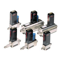
Brooks 5850 S Installation And Operation Manual (52 pages)
Digital Mass Flow Meters and Controllers
Brand:
Brooks
| Category:
Measuring Instruments
| Size: 3.88 MB
Table of Contents
Table of Contents
5
Section 1:Introduction
6
Purpose
6
How to Use this Manual
6
Description
7
Table 1-1: Flow Ranges Per Model
7
Section 2: Installation
10
General
10
Receipt of Equipment
10
Recommended Storage Practice
11
Return Shipment
11
Gas Connections
11
Mechanical Installation
12
IN-LINE Filter
12
Electrical Interfacing
13
Table 2-1: Electrical Interfacing. Smart TMF
13
Figure 2-1: Open Collector
14
Digital Communication
15
Figure 2-2: P.C. Boards with the Locations of Jumper Switches Note: Switch Number 1 Is the Switch at the Bottom
15
Table 2-2: Dipswitch Settings
16
Interconnection
17
Figure 2-3: RS-232 Interconnection of TMF and PC
17
Figure 2-4: RS-485 Multidrop Interconnection Tmfs and PC
17
Figure 2-5: TMF/C to Read-Out Cable
18
Figure 2-6: TMF/C Read-Out and Pc
18
Table 2-3: Electrical Interfacing. Smart TMF Cable
19
Section 3: Operation
20
Operating Procedure
20
Zero Adjustment
20
Calibration Procedure
20
Section 4: Maintenance
21
General
21
Troubleshooting and System Checks
21
Table 4-1: Troubleshooting
23
Cleaning Procedures
24
Calibration Procedure
24
Valve (Dis)Assembly Procedure
24
Section 5: Specification
25
Table 5-1: Flow Ranges and Pressure Ratings
26
Appendix A: Gas Conversion Tables
29
Appendix B: Dimensional Drawings
33
Appendix C:translation of CE Marking Electrical Installation Instructions
35
Appendix D: Important Safety Instructions
40
Appendix E: Modellist
45
Advertisement
Related Products
Brooks 5863
Brooks 5860i
Brooks 5861E
Brooks 5860 S
Brooks 5851 S
Brooks 5861 S
Brooks 5853 S
Brooks 5863 S
Brooks 5864S
Brooks 5851E
Brooks Categories
Measuring Instruments
Controller
Laboratory Equipment
Security System
Smoke Alarm
More Brooks Manuals
Login
Sign In
OR
Sign in with Facebook
Sign in with Google
Upload manual
Upload from disk
Upload from URL