
Subscribe to Our Youtube Channel
Related Manuals for YOKOGAWA OR8EFG


Summary of Contents for YOKOGAWA OR8EFG
- Page 1 User’s Manual Model OR8EFG KCl Filling type ORP Sensor IM 12C07J01-01E IM 12C07J01-01E 8th Edition...
-
Page 2: Introduction
<INTRODUCTION> INTRODUCTION This manual covers the OR8EFG KCl Filling type ORP Sensor. Other related items are described in the following manuals. Model Title IM No. PH8HG Guide-pipe Holder IM 12B7M2-01E PH8HF, PH8HFF Flow-Through Type Holder IM 12B07N01-01E PH8HS, PH8HSF... -
Page 3: For The Safe Use Of This Equipment
The product is provided on an “as is” basis. YOKOGAWA shall have neither liability nor responsibility to any person or entity with respect to any direct or indirect loss or damage arising from using the product or any defect of the product that YOKOGAWA can not predict in advance. IM 12C07J01-01E... -
Page 4: After-Sales Warranty
If we replace the product with a new one, we won’t provide you with a repair report. l Yokogawa warrants the product for the period stated in the pre-purchase quotation Yokogawa shall conduct defined warranty service based on its standard. When the customer site is located outside of the service area, a fee for dispatching the maintenance engineer will be charged to the customer. - Page 5 Blank Page...
-
Page 6: Table Of Contents
<CONTENTS> Model OR8EFG KCl Filling type ORP Sensor IM 12C07J01-01E 8th Edition CONTENTS INTRODUCTION .....................i For the safe use of this equipment .............ii After-sales Warranty ...................iii Specification ..................... 1-1 1.1 Standard Specifications ................... 1-1 1.2 Model and Suffix codes ..................1-3 External Dimensions .................. - Page 7 Blank Page...
-
Page 8: Specification
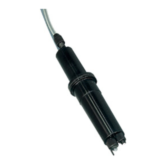
< 1. Specification > Specification The Model OR8EFG KCl filling type ORP Sensor permits stable ORP measurement even for solutions having comparatively severe properties. This sensor can be mounted on either an PH8HF flow-through holder or an PH8HS submersion holder, or its can be used alone suspended in the solution (a maximum depth of 3 meters). 1.1 Standard Specifications Measurement: Oxidation-reduction potential of a solution Measurement principle: Metallic electrode method... - Page 9 If you have any questions about the wetted part construction of the product, be sure to contact Yokogawa. IM 12C07J01-01E...
-
Page 10: Model And Suffix Codes
Two 200 mL polyethylene cups One cleaning bottle One pack of quinhydrone reagent powder (three bags, 250 mL solution each) One 250 mL polyethylene bottle Either /KCLL or /KCLP is required for OR8EFG-¨¨-¨¨-TT2. IM 12C07J01-01E 8th Edition : Apr. 27, 2020-00... - Page 11 K9142TH One for OR8ERG,OR8EFG K9142HW One for OR8EFG/TF KCl solution (3.3mol/L) K9084LP Six 250 mL polyethylene bottles KCl powder (for OR8EFG) K9020XU 8 bags, each for preparation of 250mL Reagent for Quinhydrone K9024EC 3 bags, each for preparation of 250mL...
-
Page 12: External Dimensions
14 (Black) Approx. Approx. 16 (Green) Model and codes Weight (kg) OR8EFG - - 03 - TT - *A Approx. 3000 Approx. 0.4 OR8EFG - - 05 - TT - *A Approx. 5000 Approx. 0.6 OR8EFG - - 07 - TT - *A Approx. - Page 13 Blank Page...
-
Page 14: Installation
Preparation for Installation 2.1.1 Unpacking and Inspection The Model OR8EFG ORP Sensor is well packed so as to prevent damage during shipment. After removing the sensor from its shipping container, visually check the sensor for damage. NOTE 1. When delivered, the "indicator electrode" and the "liquid junction" are packed separate from the sensor body. -
Page 15: Mounting Liquid Junction
(3) If specified, a reserve tank containing 250 mL KCl solution and mounting hardware to hold this tank are supplied with the OR8EFG ORP Sensor. Attach the holding hardware to the pipe (2-inch). Connect the reserve tank to the KCl solution supply tube of the sensor. Remove the cap from the tank and screw the tube connector securely into the tank. - Page 16 < 2. Installation > (5) Attach the "stopper" supplied with the guide pipe to the sensor cable. Fix the sensor cable so that the sensor tip projects 20 to 30 mm out from the pipe end when the ORP Sensor is suspended in the guide pipe as shown in Figure 2.4. NOTE If the sensor tip does not project out from the pipe end, the measured value may not respond promptly to the ORP variations of the measured solution.
-
Page 17: Installing Sensor In Ph8Hs Submersion Holder
< 2. Installation > 2.2.2 Installing Sensor in PH8HS Submersion Holder To install the sensor in the submersion holder, proceed as follows: (1) Pass the sensor cable through the sensor holder. If the submersion holder remains installed, remove the sensor holder in any case. For a pipe-mounting submersion holder without a cleaner, loosen the sensor holder nut to remove the holder. - Page 18 < 2. Installation > Clamp (Screw) Cleaner Holder Sensor Holder F2.7.ai Figure 2.7 Removal of Sensor Holder (with Cleaner) To install the sensor cable in the sensor holder, first remove the protector screwed onto the sensor holder end and then remove the protective foam piece (for shipping; thus, it is not necessary after the sensor is installed in the holder). Pass the sensor cable through the O-ring then attach the O-ring to the sensor flange (see Figure 2.7).
- Page 19 (4) If specified, a reserve tank containing 250 mL KCl solution and mounting hardware to hold this tank are supplied with the OR8EFG ORP Sensor. Attach the mounting hardware to the pipe (2-inch). Connect the reserve tank to the KCl solution supply tube of the sensor. Remove the cap from the tank and screw the tube connector securely into the tank.
-
Page 20: Installing Sensor In Flow-Through Holder
(3) If specified, a reserve tank containing 250 mL solution and mounting hardware to hold this tank, or a medium pressure reserve tank are supplied with the OR8EFG ORP Sensor. Attach the mounting hardware for general purpose reserve tank to a pipe (2-inch). Connect the general purpose reserve tank to the KCl solution supply tube of the sensor. Remove the cap from the tank and screw the tube connector securely into the tank. - Page 21 < 2. Installation > l When a general purpose reserve tank is used. First, mount the reserve tank on the holding hardware with the tube connection part directed downwards. Using the pin supplied with the tank, make several holes in its top (see Figure 2.3). Stand the sensor upside down at a position lower than the reserve tank as shown in Figure 2.3 so that KCl solution flows from the tank into the sensor. When the KCl solution fills the sensor and overflows from the liquid junction mounting hole, securely screw the liquid junction into the mounting hole.
-
Page 22: Orp Sensor Cable Wiring Procedure
< 2. Installation > ORP Sensor Cable Wiring Procedure 2.3.1 Processing of Cable Inlet Hole Open the cable inlet hole in terminal box using the supplied punch tool. The location of the cable inlet hole is shown by the circle-shaped groove under the case. The end of the supplied punch tool is put in the center of this circle and it is tapped with appropriate force. -
Page 23: Connecting Sensor Cable To Two-Wire Orp Transmitter
2-10 < 2. Installation > Put the nut in place, and screw it onto the main body sufficiently. At this time, loosen the cap so that the cable is not twisted. After fixing the main body, tighten the cap to keep moisture out of the equipment. However if the cap is screwed up too tight, the cable will be damaged. Attach the nut in the direction shown here (so that it engages the detent groove). Gasket Main unit F2.15.ai... -
Page 24: Connecting Sensor Cable To Four-Wire Orp Converter
2-11 < 2. Installation > 2.3.4 Connecting Sensor Cable to Four-wire ORP Converter To connect the sensor cable to a Four-wire ORP Converter, proceed as follows: (1) Loosen the four screws that tighten the converter cover. Then open the converter cover. (2) Connect the sensor cables to the relevant terminals of the converter: First, remove the nut from the cable gland. - Page 25 Blank Page...
-
Page 26: Maintenance On Operation
< 3. Maintenance on operation > Maintenance on operation Operation and Periodic Maintenance 3.1.1 Calibrating ORP Sensor Using Checking Solutions Dirt attached to the liquid junction or sensitive parts (platinum electrodes) may have an adverse effect on electromotive force and response characteristics, so ORP sensors require periodic cleaning for good operating conditions. ORP sensors should be checked and calibrated if the following conditions are met. -
Page 27: Replenishment Of Kcl Solution
< 3. Maintenance on operation > 3.1.3 Replenishment of KCl Solution When the KCl solution in the tank seems to be nearly exhausted while using a ORP Sensor with general type reserve tank, replace the reserve tank with new one (provided separately as spare part). Instead of tank replacement, when a KCl solution prepared using KCl powder is used for replenishment, use 3.3 mol/L solution by dissolving 246 g of KCl powder in pure water to make exactly one liter of solution. -
Page 28: Cleaning Indicator Electrode And Liquid Junction
< 3. Maintenance on operation > 3.1.4 Cleaning Indicator Electrode and Liquid Junction Staining of a indicator electrode or liquid junction can cause measurement errors. Therefore, if he measured solutions tend to stain the electrode, the indicator electrode and liquid junction must be cleaned periodically - depending on the degree of staining. -
Page 29: Replacing Consumable Parts
O-ring inside the indicator electrode. For individual replacement of the O-ring, use the one recommended by Yokogawa. When installing the O-ring, wind a slip of paper or tape around the thread part on the indicator electrode so as not to scratch the O-ring. - Page 30 (Length by meter, max.100 m) K9142QR O-Ring, 6 mm ID. X 9 mm OD. L9813UG 3 or 5 Clamp CMPL 12C03J01-01E All Rights Reserved, Copyright © 1984, Yokogawa Electric Corporation. Subject to change without notice. 9th Edition : Apr. 2020 (YK)
- Page 31 Medium Pressure Type Label To KCl Filling Tube Item Part No. Description K9142VG Tank Assembly (item 2 through 8) L9835DD Joint L9867BS Pressure Gauge (Range:0 to 700 kPa) G9303AE O-Ring K9142VP Bracket K9142EJ L9826AL Bracket D0117XL-A 1 U-Bolt Assembly CMPL 12C03J01-01E 9th Edition : Apr.
-
Page 32: Revision Information
Revision Information Title : Model OR8EFG KCl Filling type ORP Sensor Manual No. : IM 12C07J01-01E Apr. 2020/8th Edition Revised along with an additional code for option /TF (P.1-2, 1-3, 1-4. 3-1) CMPL 12C03J01-01E was revised to 9th edition (a part addition: Junction for /TF) Feb. 2020/7th Edition... - Page 33 Blank Page...
Need help?
Do you have a question about the OR8EFG and is the answer not in the manual?
Questions and answers