
Related Manuals for YOKOGAWA DO30G


Summary of Contents for YOKOGAWA DO30G
- Page 1 User’s Manual Dissolved Oxygen Metering System Model DO30G Dissolved Oxygen Sensor IM 12J5B3-01E IM 12J5B3-01E 6th Edition...
-
Page 2: Introduction
This manual covers all of the information on handling the DO30G Dissolved Oxygen Sensor (Style B), such as instructions on installation, inspection, and maintenance and service. Note : When system components other than DO30G have to be mentioned, descriptions of the basic system assumes that the DO402G Dissolved Oxygen Converter is used. -
Page 3: For The Safe Use Of This Equipment
• Every effort has been made to ensure accuracy in the preparation of this manual. However, when you realize mistaken expressions or omissions, please contact the nearest Yokogawa representative or sales office. -
Page 4: After-Sales Warranty
Yokogawa does not warrant conformance with the specific application at the user site. Yokogawa will not bear direct/indirect responsibility for damage due to a specific application. l Yokogawa will not bear responsibility when user configures the product into systems or resells the product. - Page 5 Blank Page...
-
Page 6: Table Of Contents
4.3 Expendables, Spare Parts and Maintenance Parts ........4-4 4.3.1 DOX8A Maintenance Parts (Expendables) Kit ........4-4 4.3.2 Parts That Should Be Kept on Hand ..........4-5 Appendix 1. How to Remove the DO30G Membrane Protective Cap ..A-1 Customer Maintenance Parts List .......... CMPL 12J5B3-01E Customer Maintenance Parts List ........CMPL 12J05B03-12E Revision Record .......................i IM 12J5B3-01E 6th Edition : Nov.20,2018-00... - Page 7 Blank Page...
-
Page 8: General
You can submerse the DO30G Dissolved Oxygen Sensor to a depth of 3 m and then put it in regular use (the sensor can withstand a pressure of up to 100 kPa). The sensor can be as- sembled into a immersion type holder or a floating ball holder. -
Page 9: Specifications
<1. General> 1.2 Specifications 1.2.1 Standard Specifications Object of Measurement: Concentration of oxygen dissolved in solution (water) Principle of Measurement: Galvanic-cell method Measurement Range: 0 to 20 ppm, 0 to 20 mg/L, or 0 to 100% (saturation) Note: The measurement range must be entered through the dissolved oxygen converter. Resistance Temperture Detector (RTD) : Pt 1000 Construction:... -
Page 10: Model And Suffix Codes
<1. General> 1.2.2 Model and Suffix Codes • DO Sensor Option Code Suffix Code Description Model Dissolved Oxygen Sensor DO30G – Always -NN Membrane thickness 50 µm Cable length Pin terminal *1 Cable terminal Fork terminal M4 ring terminal *2 *1 Select pin terminal for FLXA402, DO402G, DO202, and FLXA202/ FLXA21.When terminal box is used, select WTB10-DO3. -
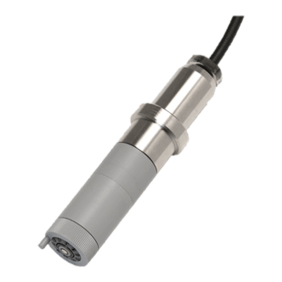
Page 11: External View And Dimensions
15 16 Pin terminals 11 12 14 15 16 Model and Suffix Codes Weight (kg) DO30G - NN - 50 - 03 - PN 3 000 Approx. 0.6 Approx. DO30G - NN - 50 - 05 - PN Approx. 0.8... -
Page 12: Components And Their Functions
Silver electrode Temperature Detector Cutaway View of the Sensor Tip F03.ai Figure 2.1 Components and Their Functions of DO30G Dissolved Oxygen Sensor CAUTION Do not loosen the permeable-membrane assembly locknut except when replacing the assembly. IM 12J5B3-01E 6th Edition : Nov.20,2018-00... - Page 13 Blank Page...
-
Page 14: Installing The Sensor And Connecting The Cable
3.1.1 Removal of Parts for Transportation and Storage A cap to prevent the membrane from being damaged when transporting the sensor is mounted at the tip of the DO30G Dissolved Oxygen Sensor. When installing the sensor, remove this protec- tive cap (See Appendix 1.). 3.1.2 Inspecting the Permeable Membrane Any wrinkling or damage to the permeable membrane may lead to a failure to take normal meas- urements. -
Page 15: Installation
Do not install the sensor at a depth greater than 3 m. 3.2.2 Selecting the Sensor Holder Each holder or fitting where the DO30G Dissolved Oxygen Sensor is assembled has the follow- ing characteristics. Choose a holder that suits the liquid to be measured and the measurement location. - Page 16 <3. Installing the Sensor and Connecting the Cable> [PB350G Angled Floating Ball Holder] The fitting is designed to contain the sensor in a sphere that floats on a liquid. This fitting is im- mune to large variations in the liquid level. Since the wet part is smooth and less susceptible to catching flocs, the sensor does not trap rubbish that mixes in with the SUM (Related descrip- tion: See Subsection 3.2.3).
-
Page 17: Asembling The Sensor In The Holder
<3. Installing the Sensor and Connecting the Cable> 3.2.3 Asembling the Sensor in the Holder For details on how to assmble the sensor in the holder or fitting, see the appropriate instruction manual for each holder or fitting. CAUTION Exercise care not to contaminate or wet the tip of the sensor cable when assembling the sensor. If you will not begin wiring the sensor cable immediately, take the protective measures necessary to prevent the assembly from being damaged. -
Page 18: Maintenance
<4. Maintenance> Maintenance This section describes the inspection and maintenance procedure applicable to just the dissolved oxygen sensor alone. For comprehensive inspection and tuning of the measuring system, such as calibration, see the FLXA402 4-Wire Converter instruction manual (IM 12A01F05-01EN), the DO402G Dissolved Oxygen Converter instruction manual (IM 12J05D02-01E), the FLXA202/ FLXA21, DO202 2-wire Transmitter instruction manual (IM 12J05C01-01E/IM 12A01A02-01E). -
Page 19: Inspection If Failure Occurs
<4. Maintenance> Inspection If Failure Occurs If the electrolyte and/or lead electrode within the sensor unit deteriorates and ultimately com- pletes its service life, anomalies, such as the failure to make a span adjustment, will occur. This section deals especially with the inspection and service of the dissolved oxygen sensor needed if any anomaly is found in a detected signal. - Page 20 (6) Inject 8 ml of electrolyte into the sensor body with the syringe (see Figure 4.2). Note: Always use an electrolyte prepared by Yokogawa for exclusive use with the DO30G. First, fill the sensor with the electrolyte (approx. 9 ml) and then remove approximately 1 ml so that a layer of air is present inside the sensor body.
-
Page 21: Checking Of Rtd In The Sensor
The DOX8A Maintenance Parts Kit contains, as a set, spare parts for the expendables that need to be replaced within one year after the start of use of the DO30G Dissolved Oxygen Sensor, the materials that are used during replacement, and a reagent that is used to prepare the calibration solution for zero adjustment. -
Page 22: Parts That Should Be Kept On Hand
<4. Maintenance> Table 4.1 Items Contained in the DOX8A Maintenance Parts Kit Item Part No. Remarks Must be replaced periodically, either once every 6 to 8 Electrolyte K9171DN 50 mL months or if a span adjustment is not possible. Eight to 9 ml are consumed with each replacement. Normally, these parts must be replaced at the same time Permeable-membrane that the sensor is refilled with electrolyte. - Page 23 Blank Page...
-
Page 24: Appendix 1. How To Remove The Do30G Membrane Protective Cap
Appendix 1. H ow to Remove the DO30G Membrane Protective Cap CAUTION A black rubber cap is attached to the tip of the DO30G to protect the membrane. Pulling off the cap forcefully causes a negative pressure inside the protective cap, because the protective cap sticks to the DO30G, and may stretch the membrane or damage it. - Page 25 When an appropriate stick or the like is not available. (1) As shown in the figure 4, insert a stick or the like between the DO30G (1) Hold the protective cap while holding the and protective cap. Be careful not to DO30G as shown in the figure 7.
-
Page 26: Customer Maintenance Parts List
Parts List Dissolved Oxygen Sensor Item Part No. Description K9171CH Box nut assembly K9171HM Membrane / O-ring CMPL 12J5B3-01E All Rights Reserved, Copyright © 1996, Yokogawa Electric Corporation. Subject to change without notice. 1st Edition: Oct., 1996 4th Edition: Nov., 2018... -
Page 28: Customer Maintenance Parts List
Membrane / O-Ring Set G9303NM 1 O-Ring K9171CS Membrane Assembly (50 m) L9827NG Needle L9827NH 5 ml Sylinge CMPL 12J05B03-12E All Rights Reserved, Copyright © 1996, Yokogawa Electric Corporation. Subject to change without notice. 2nd Edition : Feb. 2006 (YK) -
Page 30: Revision Record
P. 4-1, FLXA21 and DO202 manual no. added to section 4 “Maintenance.” P. 4-3, Stabilized time in a initial time for electrolysis modified. Appendix 1 “How to Remove the DO30G Membrane Protective Cap” added to end of this manual. CMPL 12J5B3-01E revised to 3rd edition (M4 ring terminal added). - Page 31 Blank Page...
Need help?
Do you have a question about the DO30G and is the answer not in the manual?
Questions and answers