
Subscribe to Our Youtube Channel
Related Manuals for Manitou 160 ATJ PLUS Euro 3


Summary of Contents for Manitou 160 ATJ PLUS Euro 3
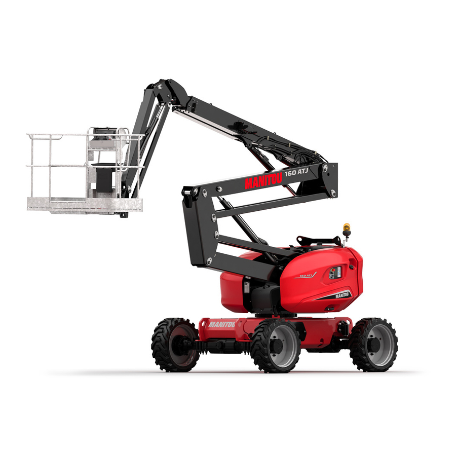
- Page 1 647532 EN (20/09/2017) 160 ATJ PLUS Euro 3 OPERATOR'S MANUAL (ORIGINAL INSTRUCTIONS)
- Page 2 - Descriptions and figures are non binding. - MANITOU reserves the right to change its models and their equipment without being required to update this manual. - The MANITOU network, consisting exclusively of qualified professionals, is at your disposal to answer all your questions.
- Page 3 MANITOU BF. Any violation of the aforementioned may lead to civil and criminal prosecution. The logos as well as the visual identity of the company are the property of MANITOU BF and may not be...
- Page 4 www.duma-rent.com 1 - OPERATING AND SAFETY INSTRUCTIONS 2 - DESCRIPTION 3 - MAINTENANCE 4 - ATTACHMENTS...
- Page 5 www.duma-rent.com 1 - OPERATING 1 - OPERATING AND SAFETY AND SAFETY INSTRUCTIONS INSTRUCTIONS...
- Page 6 www.duma-rent.com...
-
Page 7: Table Of Contents
www.duma-rent.com TABLE DES MATIÈRES INSTRUCTIONS TO THE COMPANY MANAGER OREWORD PERATOR LATFORM NSTRUCTIONS AINTENANCE INSTRUCTIONS TO THE OPERATOR OREWORD ENERAL INSTRUCTIONS RIVING INSTRUCTIONS 1-15 NSTRUCTIONS FOR WELDING AND BLOW TORCH WORK ON AN EXTERNAL STRUCTURE 1-16 PLATFORM MAINTENANCE INSTRUCTIONS 1-16 ENERAL INSTRUCTIONS 1-16 MAINTENANCE... -
Page 8: Instructions To The Company Manager
S SUITABILITY FOR USE - MANITOU has ensured that this platform is suitable for use under the standard operating conditions defined in this operator's manual, with an overload test coefficient of 1.25 and an operational test coefficient of 1.1, as stipulated in standard EN 280 for MPLP (Mobile Personnel Lifting Platforms). -
Page 9: Instructions
- The machines manufactured by MANITOU are designed to be used within the following temperature ranges: • Minimum temperature: -20°C • Maximum temperature: +45°C - Special applications are available as options for particularly cold environments. The factory fill of lubricants is for average climatic conditions, i.e. between -15°C and +35°C. For operation under more severe climatic conditions, before starting up, the systems should be drained and refilled using lubricants suited to the ambient temperatures. -
Page 10: Instructions To The Operator
www.duma-rent.com INSTRUCTIONS TO THE OPERATOR OREWORD WHENEVER YOU SEE THIS SYMBOL IT MEANS: WARNING! BE CAREFUL! YOUR SAFETY OR THE SAFETY OF THE PLATFORM IS AT RISK. The risk of accident while using, servicing or repairing your platform can be restricted if you follow the safety instructions and safety measures detailed in these instructions. - Page 11 www.duma-rent.com C - M AINTENANCE - The operator must immediately advise his superior if his platform is not in good working order or does not comply with the safety notice. - The operator is prohibited from carrying out any repairs or adjustments himself, unless he has been trained for this purpose. He must keep the platform properly cleaned if this is among his responsibilities.
-
Page 12: Driving Instructions
- Safety helmets must be worn. - MANITOU recommends a safety harness in the operator’s size be provided when the platform is in use (for the harness attachment in the basket , see chapter 2 - DESCRIPTION, CHECKING AND CONTROL INSTRUMENTS pages). - Page 13 www.duma-rent.com - Do not allow anybody to come near the working area of the platform or pass beneath an elevated load. To ensure this, mark out your working area. - Travelling on a longitudinal slope: • Ensure that you adapt the access platform’s travel speed by controlling it with the joystick. - Take into account the platform’s dimensions and its load before trying to negotiate a narrow or low passageway.
- Page 14 www.duma-rent.com If the wind is in excess of 45 km/h, do not perform any movements liable to endanger the access platform’s stability. - To visually recognise this wind speed, refer to the empirical wind evaluation scale below: BEAUFORT scale (wind speed at a height of 10 m on a flat site) Speed Speed Force...
- Page 15 www.duma-rent.com D - V ISIBILITY - Ensure good visibility on your route at all times. To increase your visibility, you can move forwards with the jib arm slightly raised (beware of the risk of falls in the basket from knocking into a low doorway, overhead electric wires, travelling cranes, highway bridges, rail tracks or any obstacle in the area in front of the platform).
- Page 16 www.duma-rent.com E - S TARTING THE PLATFORM PLATFORMS WITH I.C. ENGINES SAFETY INSTRUCTIONS - Never try to start the platform by pushing or towing it. Such operation may cause severe damage to the transmission. If towing is necessary, the platform must be placed in freewheel mode (see: 3 - MAINTENANCE). - If using an emergency battery for start-up, use a battery with the same characteristics and respect battery polarity when connecting it.
- Page 17 www.duma-rent.com F - D RIVING THE PLATFORM SAFETY NOTICE We draw the operators' attention to the risks associated with using the platform, in particular: - Risk of loss of control. - Risk of loss of lateral and frontal stability of the platform. The operator must remain in control of the platform.
- Page 18 www.duma-rent.com G - S TOPPING THE PLATFORM SAFETY NOTICE - Never leave the ignition key in the platform during the operator's absence. - Make sure that the platform is not stopped in any position that will interfere with the traffic flow and in particular the platform should not be at less than one metre from a railroad track.
-
Page 19: Instructions For Welding And Blow Torch Work On An External Structure
www.duma-rent.com NSTRUCTIONS FOR WELDING AND BLOW TORCH WORK ON AN EXTERNAL STRUCTURE Ensure that there are no hydraulic or electrolyte leaks on the platform. When welding, work in the opposite direction from the control console to avoid sparks damaging it. - Any welding and cutting (blow torch) work from the basket on a building’s metallic structures requires the following precautions to be taken: A - W... -
Page 20: Platform Maintenance Instructions
www.duma-rent.com PLATFORM MAINTENANCE INSTRUCTIONS ENERAL INSTRUCTIONS - Make sure the area is adequately ventilated before starting up the platform. - Wear clothes suitable for the maintenance of the lift truck, avoid wearing jewellery and loose clothes. Tie and protect your hair, if necessary. -
Page 21: Hydraulics
Welding operations for the purposes of maintenance or repairs must only be carried out by persons authorised by MANITOU. ASHING THE PLATFORM - Clean the platform or at least the area concerned before any intervention. -
Page 22: If The Platform Is Not To Be Used For A Long Time
The following recommendations are intended to prevent the platform from being damaged when it is withdrawn from service for an extended period. For these operations, we recommend the use of a MANITOU protective product, reference 603726. Instructions for using the product are given on the packaging. -
Page 23: Battery Charge
www.duma-rent.com ATTERY CHARGE - In the case of electric platforms, in order to preserve the batteries’ life and their capacity, check them periodically and keep the charge level constant (see: 3 - MAINTENANCE). ROTECTING THE PLATFORM - Protect cylinder rods which are not be retracted from corrosion. - Wrap the tyres. -
Page 24: Disposing Of The Platform
- Glass items can be removed and collected for processing by glaziers. ENVIRONMENTAL PROTECTION By entrusting the maintenance of your platform to the MANITOU network, the risk of pollution is limited and the contribution to environmental protection is made. WORN OR DAMAGED PARTS - Do not dump them in the countryside. - Page 25 www.duma-rent.com 1-21...
-
Page 26: Safety Decals
www.duma-rent.com SAFETY DECALS 1-22... - Page 27 www.duma-rent.com 1 - W 1-24 HITE ARROW 2 - B 1-24 LACK ARROW 3 - B 1-24 ASKET INSTRUCTIONS AND LOAD CAPACITY 1-25 AFETY INSTRUCTION 1-25 OWING 1-25 ASHING RECOMMENDATIONS 5 - L 1-25 OAD ON WHEELS 6 - L 1-26 OCATION OF ACCESS PLATFORM KEY 7 - M...
-
Page 28: White Arrow
www.duma-rent.com EANING 1 - W HITE ARROW This indicates the direction of travel when moving forward. When the removable control box is turned round on the basket, the translation controls are reversed. Identify the direction of movement by looking at the arrows on the chassis and those on the basket control console. -
Page 29: Safety Instruction
www.duma-rent.com AFETY INSTRUCTION Take note of the safety and operating instructions before you start the platform. OWING This sticker means that the platform must not be towed in the event of breakdown. ASHING RECOMMENDATIONS It is strictly forbidden to direct a pressure washer’s nozzle over the control buttons and electrical components. -
Page 30: Location Of Access Platform Key
www.duma-rent.com 6 - L OCATION OF ACCESS PLATFORM KEY The spare keys for the access platform (ignition key, control selector key, key for locking casings...) are stored in the place provided for the purpose. 7 - M ANUAL CONTROL PROCEDURE This describes the procedure for performing movements with the backup pump and the manual controls, if an accident or breakdown occurs making the electrical control boxes unusable. -
Page 31: Hand Crushing Hazard
www.duma-rent.com 9 - H AND CRUSHING HAZARD It is strictly forbidden to place your fingers or any other part of the body in the parts of the lifting system (arm, scissors, jib, etc.); risk of crushing. 10 - D ANGER KEEP AWAY It is strictly forbidden to walk under or park under the structure (arms, scissors, jib, basket, etc.) and in the access platform’s operating area. -
Page 32: Arm Strut
www.duma-rent.com 13 - A RM STRUT This sticker indicates use of a maintenance strut in the event of work being done on the platform in working position. 14 - S AFETY HOOK This sticker indicates the place where the safety harness must be attached and the number of people per attachment point. -
Page 33: Hydraulic Oil
www.duma-rent.com 17 - H YDRAULIC OIL This indicates that the tank is intended to contain only hydraulic oil. NOTE: See MAINTENANCE: LUBRICANTS 597652 18 - D IESEL This indicates that the tank is intended to contain only vehicle diesel fuel. 19 - A NTIFREEZE This sticker means that there is antifreeze in the internal combustion engine. - Page 34 www.duma-rent.com 1-30...
- Page 35 www.duma-rent.com 2 - DESCRIPTION 2 - DESCRIPTION...
- Page 36 www.duma-rent.com...
- Page 37 TABLE OF CONTENTS "EC" DECLARATION OF CONFORMITY - 160 ATJ PLUS EURO 3 IDENTIFICATION OF THE PLATFORM SPECIFICATIONS 160 ATJ PLUS EURO 3 DIMENSIONS 160 ATJ PLUS EURO 3 2-12 PLATFORM OPERATION 2-14 BASE INSTRUMENTS AND CONTROLS 2-16 BASKET INSTRUMENTS AND CONTROLS...
-
Page 38: Ec" Declaration Of Conformity - 160 Atj Plus Euro
"EC" DECLARATION OF CONFORMITY - 160 ATJ PLUS EURO 3 DÉCLARATION «CE» DE CONFORMITÉ (originale) « EC» DECLARATION OF CONFORMITY (original) La société, : MANITOU BF The company Adresse, Address 430, rue de l’Aubinière - BP 10249 - 44158 - ANCENIS CEDEX - FRANCE... - Page 39 www.duma-rent.com bg : 1) удостоверение за « СЕ » съответствие (oригинална), 2) Фирмата, 3) Адрес, 4) Техническо досие, 5) Фабрикант на описаната по-долу машина, 6) Обявява, че тази машина, 7) Отговаря на следните директиви и на тяхното съответствие национално право, 8) За машините към допълнение IV, 9)Номер на удостоверението, 10) Наименувана фирма, 15) хармонизирани...
-
Page 40: Identification Of The Platform
www.duma-rent.com IDENTIFICATION OF THE PLATFORM - In view of our policy of constantly improving our products, we may make certain modifications to our access platform range without notifying our customers in advance. - When you order parts, or when you require any technical information, always specify: NOTE: For the owner's convenience, it is recommended that a note of these numbers is made in the spaces provided, at the time of the delivery of the access platform. - Page 41 www.duma-rent.com YDROSTATIC PUMP - Pump No. - Type of codification - Manufacturer’s No. - Year of manufacture RONT AXLE - Axle type - Serial No. - Manufacturer’s No. EAR AXLE - Axle type - Serial No. - Manufacturer’s No. ONNECTION BOX FUSES - F1 250 A - F2...
-
Page 42: Specifications 160 Atj Plus Euro 3
SPECIFICATIONS 160 ATJ PLUS EURO 3 LOAD SPECIFICATIONS UNIT 160 ATJ PLUS 160 ATJ PLUS RC TOL ± Platform Rated capacity for outdoor use (Wind 45 km/h) Number of people in basket Unladen platform weight 8,100 8,100 Authorised maximum tilt °... - Page 43 www.duma-rent.com DIMENSIONS UNIT 160 ATJ PLUS 160 ATJ PLUS RC TOL ± Transport position Width 2 300 Length 6 925 Length (truck transport) 4 820 Height 2 750 Floor/ground height, in transport Turntable overrun Working position Working height 16 210 Floor height 14 210 Max.
- Page 44 www.duma-rent.com Engine UNIT 160 ATJ PLUS 160 ATJ PLUS RC TOL ± Type KUBOTA V2403-M Fuel DIESEL Number of cylinders Cubic capacity 2 434 Idling speed unladen 1 250 0/+50 Full speed unladen 2 500 Power ISO/TR (at 2400 rpm) HP/KW 46 - 34.1 Max torque (at 1800 rpm)
- Page 45 www.duma-rent.com VIBRATION LEVEL UNIT 160 ATJ PLUS 160 ATJ PLUS RC TOL ± Average quadratic values for the body: m/s² <0.5 <0.5 HYDRAULIC CIRCUIT UNIT 160 ATJ PLUS 160 ATJ PLUS RC TOL ± Main hydraulic pump Type Variable capacity BOSCH A 10VG 45 Cubic capacity Flow rate at nominal rpm, unladen l/mn...
-
Page 46: Dimensions 160 Atj Plus Euro 3
DIMENSIONS 160 ATJ PLUS EURO 3 6929 4938 2200 2370 2705 2300 1325 3680 4040 6322 2742 3160 4050 8450 7574 14200 12790 7150 2-12... - Page 47 www.duma-rent.com 2-13...
-
Page 48: Platform Operation
- MANITOU lifting platforms are intended solely to be used for lifting people, and their tools and supplies (within authorised weight limits: see the SPECIFICATIONS paragraph) to the desired operating height to reach hard-to-reach places above installations and buildings. - Page 49 www.duma-rent.com AFETY TILT If the platform reaches the maximum authorised tilt (see SPECIFICATIONS chapter), the LED 34* on the basket console flashes steadily. The vibrating buzzer 41* in the basket also sounds intermittently. All the “AGGRAVATING” movements of raising the arms and extending the telescope are forbidden as a safety measure.
-
Page 50: Base Instruments And Controls
www.duma-rent.com BASE INSTRUMENTS AND CONTROLS A - G ROUND EMERGENCY AND MAINTENANCE CONSOLE 2-16 2-16... - Page 51 www.duma-rent.com GROUND EMERGENCY AND MAINTENANCE CONSOLE 1 - IGNITION SWITCH 2 - START BUTTON 3 - GROUND OR PLATFORM CONTROL SELECTOR SWITCH 4 - EMERGENCY STOP 5 - ENGINE LOW-TEMPERATURE START AID 6 - INTERFACE SCREEN 7 - SCREEN DATA VALIDATION KEYS 8 - DEAD MAN KEY 9 - KEY FOR TILTING THE BASKET UP AND DOWN 10 - TURNTABLE ROTATION KEYS...
-
Page 52: Basket Instruments And Controls
www.duma-rent.com BASKET INSTRUMENTS AND CONTROLS B - B ASKET COMMAND AND CONTROL STATION 2-18 2-18... - Page 53 www.duma-rent.com BASKET COMMAND AND CONTROL STATION 20 - UPPER ARM LIFTING AND LOWERING AND TURNTABLE ROTATION CONTROL LEVER 21 - LOWER ARM LIFTING AND LOWERING AND TELESCOPE EXTENSION AND RETRACTION CONTROL LEVER 22 - PLATFORM FORWARD/REVERSE AND RIGHT/LEFT JOYSTICK 23 - EMERGENCY STOP 24 - "PRE-HEATING"...
-
Page 54: Ground-Based Emergency And Maintenance Station
www.duma-rent.com GROUND-BASED EMERGENCY AND MAINTENANCE STATION 1 - I GNITION SWITCH This ignition switch has two positions. POSITION A - Engine switched off and power turned off. POSITION B - Power turned on and engine preheated automatically. 2 - S TART BUTTON BUTTON 2 - Starting the engine. - Page 55 www.duma-rent.com 4 - E MERGENCY STOP This red mushroom-head circuit breaker enables you to cut off all the machine’s movements in the event of an anomaly or danger arising. - Press the knob to cut off the movements. - Turn the knob a quarter of a turn to the right to restore the power supply (the switch returns automatically to its initial position).
- Page 56 www.duma-rent.com 6 - I NTERFACE SCREEN - This screen displays all the start-up, configuration, maintenance and fault stages of the platform. - NOTE: The current system time is displayed at the top of each page. 7 - S CREEN DATA VALIDATION KEYS - These keys are used to validate the different information on the screens.
- Page 57 www.duma-rent.com 8 - "D " FUNCTION - The button needs to be held in dead man position (position B) to supply power to the base control, at the same time as the lifting or rotating function keys. 9 - K EY FOR TILTING THE BASKET UP AND DOWN These keys, used simultaneously with the button 8 in dead man position, control the horizontality correction of the basket or the complete folding of the basket in transport...
- Page 58 www.duma-rent.com 11 - K EYS FOR LIFTING AND LOWERING LOWER ARMS - These keys, used simultaneously with the button 8 in dead man position, lift and lower the lower arms. A: LIFTING THE LOWER ARMS - Hold the dead man function 8 and press key 11A. B: LOWERING THE LOWER ARMS - Hold the dead man function 8 and press on key 11B.
- Page 59 www.duma-rent.com 15 - T URNTABLE ROTATION LOCKING SYSTEM - This pin must be used when the platform is transported by truck or other means of transport (train, etc.) to stop the turntable rotating. - Remove the clip and turn the pin to the left. - Push the pin into the hole provided in the turntable.
- Page 60 www.duma-rent.com 19 - B ACKUP PUMP BUTTON - This button starts up the backup pump, which enables all of the basket movements to be performed and returns the basket to the ground in the event of a breakdown (see RESCUE PROCEDURE paragraph). To be used only in the event of engine or electrical system failure.
- Page 61 www.duma-rent.com 2-27...
-
Page 62: Basket Control Console
www.duma-rent.com BASKET CONTROL CONSOLE 20 - U PPER ARM LIFTING AND LOWERING AND TURNTABLE ROTATION CONTROL LEVER - The lever 20 is used to lift the upper arm and rotate the turntable. NOTE: This lever is controlled gradually, which enables a highly precise approach. It should be operated smoothly, without jerks. - Page 63 www.duma-rent.com 22 - P LATFORM FORWARD REVERSE MOVEMENT CONTROL LEVER - The lever 22 is used to move the platform. - Press the trigger A and the dead man pedal (see 40) to control movements from the platform control unit. - If the pedal or the trigger A are released, no movements are possible.
- Page 64 www.duma-rent.com 24 - "P " HEATING INDICATOR LIGHT This light comes on when the machine is powered on: - Either by turning the ignition key on the base (same time as the bar graph on the screen). - Or by resetting the emergency stop button on the basket console in the platform. - Wait for the indicator light to go out before activating the start button.
- Page 65 www.duma-rent.com 27 - 28 - S TEERING MODE SELECTION AND AXLE REALIGNMENT This switch has three positions. POSITION A - Selects "Crab" mode. POSITION B - Selects 2 wheel mode. POSITION C - Selects 4 wheel drive mode. In this configuration, the only possible travel speeds are: Tortoise or Ramp.
- Page 66 www.duma-rent.com 29 - H ORN CONTROL BUTTON - Pressing the button 29 will sound the horn 18. 30 - D IFFERENTIAL LOCK CONTROL BUTTON NOTE: This control must be used at the same time as translation. The differential lock enables the 2 rear drive wheel to turn at the same speed. - To use it, press the button 30.
- Page 67 www.duma-rent.com 32 - T RAVEL SPEED SELECTION SWITCH - This switch has three positions. POSITION A: TORTOISE (LOW SPEED) POSITION B: RAMP (LOW SPEED WITH FULL POWER) Only to get over very steep ramps. POSITION C: HARE (HIGH SPEED) Only with steering mode selector in position A (27 - crab movement) or in position B (27 - 2 wheel drive movement).
- Page 68 www.duma-rent.com 37 - B ASKET ROTATION SWITCH - This switch enables the basket to be rotated left and right ROTATION RIGHT - Push the switch to the right. ROTATION LEFT - Push the switch to the left. 38 - B ASKET JIB SWITCH - This switch enables you to raise and lower the jib arm RAISING THE JIB ARM...
- Page 69 www.duma-rent.com 41 - V IBRATING BUZZER - This vibrating buzzer is activated when the machine has reached the maximum authorised tilt or is overloaded. - Intermittent: machine on slope. If the authorised tilt limit is exceeded, all movements are blocked apart from lowering of the arms, thus enabling a return to an acceptable level.
-
Page 70: Screen Display - Description Of Pages
www.duma-rent.com SCREEN DISPLAY - DESCRIPTION OF PAGES 1 - PRESENTATION PAGE PRESENTATION PAGE: - When the power is switched on, an initialisation page appears briefly on the screen, then the preheat page is displayed. 2 - PREHEAT PAGES PREHEAT PAGE: - The preheat page is displayed during the adjustable preheat cycle and the bar graph increases in proportion to the preheat time that has elapsed. - Page 71 www.duma-rent.com 4 - MENU DISPLAY DISPLAYING THE MENU: - After the power has been turned on, press on to display the available menus page and select the required menu using the arrows then confirm with EDITING A SUB-MENU: - After the menu has been chosen, select the different editing choices, if required, using the arrows - Use the buttons to edit the value of the selected option, then confirm once...
-
Page 72: Definition Of Sub-Menus
www.duma-rent.com DEFINITION OF SUB-MENUS Dealers/Rental User companies Icons Menu Sub-menu Parameters Access codes Without **** Screen adjustment: Contrast, brightness. Screen adjustments Date, time, screen beep deactivation Programme and equipment code display. Codification Machine no. history display by module. Rental counter 1 - Engine hour meters Engine hour meter Diagnostic... - Page 73 www.duma-rent.com Dealers/Rental User companies Icons Menu Sub-menu Parameters Display of "CALIBRATION" icon after code is entered. 1 - Engine speed calibration 2 - Joystick calibration Lower arms max lift speed Lower arms max lowering speed Upper arm max lift speed Upper arm max lowering speed Telescope max extension speed Telescope max retraction speed...
-
Page 74: Use Of The Platform
www.duma-rent.com USE OF THE PLATFORM TRANSPORT POSITION TRANSLATION FORWARDS TRANSLATION BACKWARDS EFORE STARTING THE PLATFORM - Check the following levels: • Engine oil • Hydraulic tank oil. • Coolant. TARTING THE PLATFORM - Turn the ignition key 1 to position B to switch on the ignition (Fig. B). - Press the button 2 to start the engine (Fig. - Page 75 www.duma-rent.com OVING IN RANSPORT PERATING MODE - Before moving and using the machine, remove the locking pin 1 from the turntable (see Fig. A). - The access platform has two distinct movement modes: transport (Fig. D) and operating mode (Fig. E) (forward direction (Fig. C)). Transport mode - Transport mode: the platform's arms are in low position with the telescope retracted, the jib can be lifted to the highest point.
- Page 76 www.duma-rent.com 2-42...
- Page 77 www.duma-rent.com NSTALLATION IN THE WORKPLACE AND LIFTING - The access platform has been designed to work on a flat, horizontal surface: it is important to clear the area in which the access platform must work. - Bring the access platform to the workplace. - If necessary, load the equipment you want to carry (stack it in a manner so as not to inconvenience the operator and avoid anything falling off ).
- Page 78 www.duma-rent.com OADING UNLOADING THE ACCESS PLATFORM Check that the safety instructions associated with the flatbed have been correctly applied before loading the access platform and ensure that the driver of the vehicle has been informed of the dimensional characteristics and ground of the platform (see SPECIFICATIONS chapter).
- Page 79 www.duma-rent.com ASHING DOWN THE ACCESS PLATFORM - Fix wedges on the truck bed in front of and behind each of the access platform’s tyres 2 (Fig. E). - Also fix wedges to the truck bed on the outside and the inside of each tyre 3 (Fig. D). - Fasten the access platform to the transport platform with straps or chains that are sufficiently strong 4 (Fig.
-
Page 80: Rescue Procedure
www.duma-rent.com RESCUE PROCEDURE - This section describes the procedures to follow and the controls to be used in the event of a problem (if the access platform breaks down or there is a person stuck in the basket) while the access platform is being used. - When first taking over the machine and regularly thereafter, this procedure must be read and thoroughly understood by the operator and all the people whose responsibilities focus around activities in contact with the machine. - Page 81 www.duma-rent.com To extend and retract the telescope (position the lever at II). - Press the button 3 (Fig. C) to supply power to the distributor and at the same time pull the lever (Fig. E) towards: • A - telescope retraction •...
- Page 82 www.duma-rent.com VERRIDE FROM THE BASKET - Press the button 39 (Fig. J) to activate the backup pump and at the same time use the basket controls - (See INSTRUMENTS AND CONTROLS chapter - B - PLATFORM CONTROL CONSOLE) Only to be used to bring the basket back down to the ground in the event of an engine failure.
- Page 83 www.duma-rent.com PROPORTIONAL DISTRIBUTOR Raising of lower Lowering of arms lower arms Telescope Telescope extension retraction Lowering of Raising of upper arm upper arm Left/right turntable rotation Jib lifting/lowering 2-49...
- Page 84 www.duma-rent.com Jib lifting MAIN DISTRIBUTOR Left turntable rotation Jib lowering Right turntable rotation 2-50...
-
Page 85: Options
When the generator starts up, voltage peaks may occur. Use the switch on the basket console to activate the generator. Reminder: - Unladen idling speed of 160 ATJ Plus Euro 3 (factory setting) with 1,400 rpm 3.5 kW generator option... - Page 86 www.duma-rent.com 2-52...
- Page 87 www.duma-rent.com 3 - MAINTENANCE 3 - MAINTENANCE...
- Page 88 www.duma-rent.com...
- Page 89 TABLE OF CONTENTS ORIGINAL MANITOU SPARE PARTS AND EQUIPMENT START-UP CHECKLIST FILTER CARTRIDGES AND BELTS SAFETY COMPONENTS LUBRICANTS AND FUEL 3-10 SERVICING SCHEDULE 160 ATJ P 3-12 A - DAILY OR EVERY 10 HOURS OF SERVICE 3-16 B - EVERY 50 HOURS OF SERVICE...
-
Page 90: Original Manitou Spare Parts And Equipment
- Improvements due to experience feedback. - Training of the operating personnel. - Only the MANITOU network knows the personnel lifting platform’s design in detail and therefore has the best technical capabilities for providing maintenance. ORIGINAL REPLACEMENT PARTS ARE DISTRIBUTED EXCLUSIVELY BY MANITOU AND ITS DEALER NETWORK. -
Page 91: Start-Up Checklist
www.duma-rent.com START-UP CHECKLIST 0 = OK 1 = Missing 2 = Incorrect ENGINE ATTACHMENTS 01 Air filter 01 Fitting on machine 02 Fuel tank 02 Hydraulic couplings 03 Fuel lines - Filter CABIN / PROTECTOR /ELECTRIC CIRCUIT 04 Injection or carburising system 01 Seat 05 Radiator and cooling system 02 Dashboard and radio... -
Page 92: Filter Cartridges And Belts
www.duma-rent.com FILTER CARTRIDGES AND BELTS ENGINE ENGINE OIL FILTER FAN BELT Part number: 749613 Part number: 749605 Change: 500 H Change: 500 H DRY AIR FILTER CARTRIDGE Part number: 227959 Clean: 50 H Change: 500 H DRY AIR FILTER SAFETY CARTRIDGE Part number: 227960 Change: 1,000 H* FUEL FILTER CARTRIDGE... -
Page 93: Safety Components
www.duma-rent.com SAFETY COMPONENTS ELECTRICITY TILT SENSOR DEAD MAN PEDAL Part number: 52521690 Part number: 831136 ARM DOWN SENSOR OVERLOAD SENSOR Part number: 833439 Part number: 676845 TELESCOPE SENSOR PRESSURE SWITCH Part number: 52522884 Part number: 52524496... -
Page 94: Lubricants And Fuel
USE THE RECOMMENDED LUBRICANTS AND FUEL: - For topping up, oils may not be miscible. - For oil changes, MANITOU oils are perfectly appropriate. DIAGNOSTIC ANALYSIS OF OILS If a service or maintenance contract has been organised with the dealer, a diagnostic analysis of engine and axle oils may be requested depending on the rate of use. - Page 95 LIFTING STRUCTURE UNITS TO BE LUBRICATED RECOMMENDATION PACKAGING PART NUMBER GENERAL GREASING MANITOU grease Cartridge 479330 High Performance 400 g TURNTABLE CROWN GEAR & BEARING RACEWAY LUBRICATION Shell oil TURNTABLE RING GEAR LUBRICATION Aerosol 744802 GL 205 OIL MANITOU oil...
-
Page 96: Servicing Schedule 160 Atj Plus Euro 3
SERVICING SCHEDULE 160 ATJ PLUS EURO 3 (1): MANDATORY 500 HOUR OR 6 MONTH SERVICE. This service must be carried out after approximately the first 500 hours of operation or within the 6 months following the start-up of the machine (whichever occurs first). - Page 97 www.duma-rent.com A = ADJUST, C = CHECK, G = GREASE, N = CLEAN, PAGE P = BLEED, R = REPLACE, V = DRAIN ELECTRICITY Condition of the joystick bellows 3-14 <<< <<< <<< <<< <<< <<< Battery electrolyte level 3-16 <<<...
-
Page 98: A - Daily Or Every 10 Hours Of Service
www.duma-rent.com A - DAILY OR EVERY 10 HOURS OF SERVICE A1 - GENERAL INSPECTION CHECK - Inspect the machine thoroughly and check that there is no weld cracking, corrosion or structural damage, loose or missing screws, hydraulic leaks, damaged control cable or loose electrical connections. A2 - FUNCTIONAL INSPECTION CHECK Any platform malfunction must be detected before the platform is started up each day. - Page 99 www.duma-rent.com A3 - ENGINE OIL LEVEL CHECK Set the access platform on level ground with the engine off and let the oil drain into the sump. - Open the left-hand covers. - Remove the dipstick 1 (Fig. A1). - Wipe the dipstick and check the level between the two upper notches A (Fig. A1). - If necessary, add oil (see: LUBRICANTS chapter) through the filling port 2 (Fig.
- Page 100 www.duma-rent.com A6 - BRAKING A4/1 CHECK Check that the cotter pins 1 (Fig. A4/1) and 2 (Fig. A4/2) are present on the rear axle. If these cotter pins are not present, the machine no longer has any brakes. A4/2 A7 - HYDRAULIC OIL LEVEL CHECK Put the platform in transport position on level ground with the engine stopped.
- Page 101 www.duma-rent.com A10 - CONDITION OF THE SAFE MAN SYSTEM (OPTION) A8/1 CHECK Press the safety edge (Fig. A8/1) and check: > That all the platform movements stop. > Operation of the flashing blue light and horn. > Operation of the platform's movements when you press the OFF button (Fig. A8/2) once. If the safety edge is faulty, the blue flashing light will flash quickly and a special beep will be activated.
-
Page 102: B - Every 50 Hours Of Service
www.duma-rent.com B - EVERY 50 HOURS OF SERVICE Carry out the operations described previously as well as the following operations. B1/1 B1 - BATTERY ELECTROLYTE LEVEL CHECK Check the electrolyte level in each cell of the battery. If the ambient temperature is high, check the level more frequently than every 50 hours of service. - Page 103 www.duma-rent.com B3 - AXLES B3/1 B3/2 GREASE - The oilers of the front and rear wheel reduction gear pivots 1 (Fig. B3/1) and 2 (Fig. B3/2) (8 oilers) - The oilers of the front axle oscillation axis 3 (Fig. B3/3) and 4 (Fig. B3/4) (2 oilers). B3/3 B3/4 - The oilers of the transmission universal joint:...
- Page 104 www.duma-rent.com B5 - ALTERNATOR/FAN/CRANKSHAFT BELT TENSION B5/1 ADJUST - Open the left-hand covers. - Check the belt for signs of wear and cracks and change if necessary (see 3 - M AINTENANCE: FILTER CARTRIDGES AND BELTS). - Check the tension between the crankshaft and alternator pulleys. - Pressing with your thumb (98 N), the tension A (Fig.
- Page 105 www.duma-rent.com B7 - DRY AIR FILTER CARTRIDGE B7/1 CLEAN If the platform is being used in a very dusty atmosphere, reduce this interval and see the FILTER CARTRIDGES AND BELTS chapter. - Open the left-hand covers. - Unclip the cover 1 (Fig. B7/1). - Release the filter cartridge 2 (Fig.
-
Page 106: C - Every 250 Hours Of Service
www.duma-rent.com C - EVERY 250 HOURS OF SERVICE C1 - FRONT AND REAR AXLE DIFFERENTIAL OIL LEVEL C1/1 CHECK Set the platform on level ground with the engine stopped. DIFFERENTIAL: - Remove the cap 1 (Fig. C1/1). The oil level should be flush with the hole. - If necessary, add oil (see: LUBRICANTS chapter) through the same hole. - Page 107 www.duma-rent.com C3 - FRONT AND REAR WHEEL REDUCTION GEAR OIL LEVEL CHECK Set the platform on level ground with the engine stopped. - Check the level on each front wheel reducer. - Place level plug 1 (Fig. C3) in the horizontal position. - Remove the level plug, the oil should be flush with the edge of the hole.
- Page 108 www.duma-rent.com C7 - TURNTABLE REDUCTION GEAR BRAKE/REDUCER LEVEL CHECK Set the platform on level ground with the engine stopped. - Remove the interior cowl from the turntable. - The reduction gear is presented with the valve block to the rear. - Remove the filling-breather cap 1 (Fig.
- Page 109 www.duma-rent.com C9 - SHAFTS GREASE - Clean and then lubricate the following points with grease (see: the LUBRICANTS chapter) and remove any surplus. Key: SHAFT BALL JOINT 3-23...
- Page 110 www.duma-rent.com C10 - TIGHTENING OF THE SCREWS THAT FIX THE AXLES TO THE CHASSIS CHECK - The tightening of the screws should be checked at the latest after 50 hours of service. Then the check should be repeated every 250 hours of service.
- Page 111 www.duma-rent.com C14 - FUEL FILTER C14/1 CLEAN - Set the platform on level ground with the engine stopped. - Open the left-hand covers. - Close the fuel valve 1 (Fig. C14/1) in the OFF position. - Carefully clean the outside of the filter and its holder to prevent dust from getting into the system.
- Page 112 www.duma-rent.com C16 - OVERLOAD CHECK The PIPE CRADLE or PANEL CRADLE attachments must be removed before checking the overload, see 4 - ATTACHMENTS. - Switch on the engine. - Place the platform in the transport position. - Place a uniformly distributed weight of 440 kg in the basket. Result: •...
- Page 113 www.duma-rent.com 3-27...
-
Page 114: D - Every 500 Hours Of Service
www.duma-rent.com D - EVERY 500 HOURS OF SERVICE D1 - DRY AIR FILTER CARTRIDGE D1/1 REPLACE The air used for combustion is purified by a dry air filter. It is therefore prohibited to use the platform with a cartridge that has been removed or damaged. - Open the left-hand covers. - Page 115 www.duma-rent.com D3 - HYDROSTATIC TRANSMISSION OIL FILTER CARTRIDGE REPLACE REPLACING THE HYDROSTATIC TRANSMISSION OIL FILTER CARTRIDGE - Switch off the engine. - Lift up the engine hood. - Unscrew the body of the filter 1 (Fig. D3). - Remove the hydrostatic transmission oil filter cartridge and replace it with a new one. - Make sure that the cartridge is correctly positioned and refit the cover.
- Page 116 www.duma-rent.com D5 - HYDRAULIC OIL D5/1 DRAIN - REPLACE - Set the platform on level ground in transport position with the engine stopped. DRAINING THE OIL - Place a container under draining port 1 (Fig. D5/1) and loosen the clamp 2 (Fig. D5/1). - Remove the drain plug 1 (Fig.
- Page 117 www.duma-rent.com D8 - TURNTABLE REDUCTION GEAR BRAKE/REDUCER DRAIN - REPLACE Set the platform on level ground with the engine stopped. - Remove the interior cowl from the turntable. - The reduction gear is presented with the valve block to the rear. - Remove the filling-breather cap 2 (Fig.
- Page 118 www.duma-rent.com D10 - BATTERY ELECTROLYTE SPECIFIC GRAVITY CHECK 1.240 1.250 The electrolyte’s specific gravity varies in accordance with the temperature but a 1.260 minimum value of 1,260 at 16°C must be maintained. 1.270 Within the hatched area (Fig. D10), the battery is normally charged. 1.280 Above the hatched area, the battery should be recharged.
- Page 119 www.duma-rent.com D14 - ENGINE OIL D15/1 DRAIN - REPLACE D15 - ENGINE OIL FILTER REPLACE - Set the access platform on a horizontal surface, leave the engine idling for a few minutes and then switch it off. DRAINING THE OIL - Open the left-hand covers.
-
Page 120: E - Every 1,000 Hours Of Service
www.duma-rent.com E - EVERY 1,000 HOURS OF SERVICE E1 - FUEL TANK E1/1 DRAIN - CLEAN Never smoke or approach the tank with a naked flame during these operations. Place the machine on level ground, perform a 90° rotation (so that the drain plug is not over the chassis) and switch off the engine. - Page 121 www.duma-rent.com E3 - FRONT AND REAR AXLE DIFFERENTIAL OIL E3/1 DRAIN - REPLACE Place the platform on level ground with the engine stopped and the differential oil still warm. - Place a receptacle under the drain plugs 1 (Fig. E3/1: front axle) (Fig. E3/2: rear axle). - Remove the level and filling plug 2 (Fig.
- Page 122 www.duma-rent.com E5 - HYDRAULIC CIRCUIT STRAINER E5/1 CLEAN - Drain the oil (see: § D15) - Unscrew the six fastening screws 1 (Fig. E5/1) from the closure plate 2 (Fig. E5/1). - Unscrew the strainer 3 (Fig. E5/2) in the tank and clean it using a compressed air jet. - Refit the strainer in the tank and refit the closure plate 2 (Fig.
-
Page 123: F - Every 2,000 Hours Operation
www.duma-rent.com F - EVERY 2,000 HOURS OPERATION Carry out the operations described previously as well as the following operations. F1/1 F1 - COOLANT DRAIN - REPLACE These operations are to be carried out as necessary or once a year as winter approaches. Place the platform on level ground with the engine stopped and cold. - Page 124 www.duma-rent.com Carry out the operations described previously as well as the following operations. F2 - VALVE SETS (*) CHECK - ADJUST F3 - WATER PUMP AND THERMOSTAT (*) CHECK F4 - ALTERNATOR AND STARTER (*) CHECK F5 - HYDRAULIC OIL TANK (*) CLEAN F6 - HYDRAULIC CIRCUIT PRESSURES (*) CHECK...
-
Page 125: G - Occasional Maintenance
www.duma-rent.com G - OCCASIONAL MAINTENANCE G1 - FUEL SYSTEM G1/1 BLEED These operations are only to be carried out in the following cases: - A component of the fuel system replaced or drained. - Make sure that the fuel level in the tank is high enough and turn the ignition key to notch 2. - Page 126 G2 - WHEELS G2/1 CHANGE For this operation, we advise you to use the hydraulic jack MANITOU P/N 505507 and the safety support prop MANITOU P/N 554772. - If possible, stop the platform on firm, level ground. - Shut down the platform (see: 1 - OPERATING AND SAFETY INSTRUCTIONS: DRIVING INSTRUCTIONS UNLADEN AND LADEN).
- Page 127 - Take into account the position of the access platform centre of gravity for lifting. - Place the hooks in the fastening points A provided for this purpose. - Grasp the end of the front axle flared tubes with flexible straps. 160 ATJ PLUS Euro 3 CENTRE OF GRAVITY...
- Page 128 www.duma-rent.com G4 - PLATFORM ON A TRUCK BED TRANSPORT - See chapter 2 : LOADING/UNLOADING THE PLATFORM. G5 - FREEWHEEL G5/1 ACTIVATING If the platform is to be towed, follow the instructions below. The platform may only be towed for a short distance and this must be by a machine with high braking power in order to hold it and with a connecting bar between the two machines.
- Page 129 www.duma-rent.com G7 - MAINTENANCE PROP G7/1 If you need to work on the arms, the turntable, the engine, etc. Follow the instructions below: - From the base console, lift the lower arms until the upper hinge is 1 m above the counterweight (Fig.
- Page 130 www.duma-rent.com 3-44...
- Page 131 www.duma-rent.com 4 - ATTACHMENTS 4 - 1...
- Page 132 www.duma-rent.com 4 - ATTACHMENTS INTRODUCTION PIPE CRADLE Part no. 52571261OPT PANEL CRADLE Part no. 52571261OPT INTRODUCTION IMPORTANT The PIPE CRADLE and PANEL CRADLE attachments cannot be installed at the same time on the same platform: - The PANEL CRADLE must be removed if the PIPE CRADLE is installed. - The PIPE CRADLE must be removed if the PANEL CRADLE is installed.
- Page 133 www.duma-rent.com 4 - 3...
- Page 134 www.duma-rent.com PIPE CRADLE Part no. 52571261OPT INSTALLATION IMPORTANT The nuts 5 must be replaced whenever the attachment is refitted. Inspect all of the other components of the attachment before each new installation and replace if necessary. Clean the stickers to make them legible and replace any stickers that are illegible or damaged. Check that the stickers are present whenever spare parts have been replaced.
- Page 135 www.duma-rent.com - Place the second cradle 1 in the basket between the two pipes A2 and B2 and screw it to the basket like the first cradle. NOTE: position the safety sticker facing outwards. - Adjust the distance between the two cradles 1. - Tighten the nuts 5 crosswise: •...
- Page 136 www.duma-rent.com INSTRUCTIONS FOR USE IMPORTANT Check that the pipe cradle is adjusted correctly, ADJUSTMENT. The machine and the basket must be level before the pipe(s) is (are) positioned on the pipe cradle. The length of the pipe(s) must not exceed the width of the basket. The pipe(s) must be centred with the basket.
- Page 137 www.duma-rent.com ADJUSTMENT IMPORTANT The cradles must rest on the basket floor. The cradles must be fitted symmetrically on each side of the basket and must be perpendicular to the basket floor. - Loosen the nuts 2. - Adjust the width between the cradles 1. - Retighten the nuts 5 crosswise: •...
- Page 138 www.duma-rent.com PANEL CRADLE Part no. 52571261OPT INSTALLATION IMPORTANT The nuts 6 and 13 must be replaced whenever the attachment is refitted. Inspect all of the other components of the attachment before each new installation and replace if necessary. Clean the stickers to make them legible and replace any stickers that are illegible or damaged. Check that the stickers are present whenever spare parts have been replaced.
- Page 139 www.duma-rent.com IMPORTANT Only configurations I and II are authorised - Choose one of the two configurations: CONFIGURATION Minimum panel width (pi) (6.5) Maximum panel width (pi) Maximum panel height (pi) - Remove the screws A or B (screw 11, washers 12 and nuts 13) depending on the configuration chosen.
- Page 140 www.duma-rent.com DISASSEMBLY IMPORTANT The nuts 6 must be replaced whenever the attachment is refitted. It is recommended to scrap them each time it is disassembled and to replace them for the next installation. It is recommended to inspect all of the other components each time the attachment is disassembled and to replace them if necessary. Store the attachment in a clean, dry place.
- Page 141 www.duma-rent.com INSTRUCTIONS FOR USE IMPORTANT The machine and the basket must be level before a panel can be placed on the panel cradle. The panel(s) must be centred with the basket. - Place the machine in the transport position on level ground. - If required, adjust the basket height.
- Page 142 www.duma-rent.com IMPORTANT Only configurations I and II are authorised, INSTALLATION to modify the configuration. CONFIGURATION Minimum panel width (pi) (6.5) Maximum panel width (pi) Maximum panel height (pi) PIPE CRADLE STICKER Part no. 52557917 Indicates the maximum permissible weight on the panel cradle and the maximum dimensions of the panel(s).
Need help?
Do you have a question about the 160 ATJ PLUS Euro 3 and is the answer not in the manual?
Questions and answers