Page 1
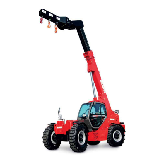
41013 Castelfranco Emilia (MO) ( Tel.059/959811 - Fax 059/959850) YOUR DEALER 648641 EN (02/02/2012) MHT 7140 T-E3 MHT 10180 LT-E3 MHT 10225 LT-E3 OPERATOR’S MANUAL THIS OPERATOR’S MANUAL MUST BE KEPT IN THE LIFT TRUCK AND MUST BE READ AND UNDERSTOOD BY OPERATORS.
Page 3
1 - OPERATING AND SAFETY INSTRUCTIONS 2 - DESCRIPTION 3 - MAINTENANCE 4 - ELECTRIC AND HYDRAULIC SYSTEMS 5 - ADAPTABLE ATTACHMENTS IN OPTION ON THE RANGE 6 - SPECIFIC AUSTRALIA Operator manual supplement: 01/12/2011 1ST DATE OF ISSUE 02/02/2012 UPDATE( chapters-6 for load charts Specific Australia) THE TEXTS AND ILLUSTRATIONS IN THIS DOCUMENT MUST NOT BE REPRODUCED EITHER WHOLLY OR IN PART.
TABLE OF CONTENTS INSTRUCTIONS TO THE COMPANY MANAGER 1 - 4 THE SITE 1 - 4 THE OPERATOR 1 - 4 THE LIFT TRUCK 1 - 4 A - THE LIFT TRUCK’S SUITABILITY FOR THE JOB 1 - 4 B - ADAPTATION OF THE LIFT TRUCK TO STANDARD ENVIRONMENTAL CONDITIONS 1 - 4 C - MODIFICATION OF THE LIFT TRUCK 1 - 5...
A - THE TRUCK’S SUITABILITY FOR THE JOB - MANITOU has ensured that this lift truck is suitable for use under the standard operating conditions defined in this operator’s manual, with a STATIC test coefficient OF 1.33 and a DYNAMIC test coefficient OF 1, as specified in harmonized norm EN 1459 for variable range trucks.
C - MODIFICATION OF THE LIFT TRUCK - For your safety and that of others, you must not change the structure and settings of the various components used in your lift truck (hydraulic pressure, calibrating limiters, I.C. engine speed, addition of extra equipment, addition of counterweight, unapproved attachments, alarm systems, etc.) yourself.
INSTRUCTIONS FOR THE OPERATOR PREAMBLE WHENEVER YOU SEE THIS SYMBOL IT MEANS: WARNING ! BE CAREFUL ! YOUR SAFETY OR THE SAFETY OF THE LIFT TRUCK IS AT RISK. The risk of accident while using, servicing or repairing your lift truck can be restricted if you follow the safety instructions and safety measures detailed in these instruction.
• Right-hand column - With a PLATFORM-fitted lift truck, people can only be lifted using platforms designed by MANITOU for the purpose. - MANITOU sells equipment specifically designed for lifting people (OPTION PLATFORM lift truck, contact your dealer).
OPERATING INSTRUCTIONS UNLADEN AND LADEN A - BEFORE STARTING THE LIFT TRUCK - Carry out daily maintenance (see: 3 - MAINTENANCE: A - DAILY OR EVERY 10 HOURS SERVICE). - Make sure the lights, indicators and windscreen wipers are working properly. - Make sure the rear view mirrors are in good condition, clean and properly adjusted.
C - ENVIRONMENT - Comply with site safety regulations. - If you have to use the lift truck in a dark area or at night, make sure it is equipped with working lights. - During handling operations, make sure that no one is in the way of the lift truck and its load. - Do not allow anybody to come near the working area of the lift truck or pass beneath an elevated load.
E - STARTING THE LIFT TRUCK SAFETY INSTRUCTIONS The lift truck must only be started up or maneuvered when the operator is sitting in the driver’s cab, with his seat belt adjusted and fastened. - Never try to start the lift truck by pushing or towing it. Such operation may cause severe damage to the transmission. If necessary, to tow the lift truck in an emergency, the transmission must be placed in the neutral position (see: 3 - MAINTENANCE: G - OCCASIONAL MAINTENANCE).
- Use the rear-view mirrors frequently. - Drive round obstacles. - Never drive on the edge of a ditch or steep slope. - It is dangerous to use two lift trucks simultaneously to handle heavy or voluminous loads, since this operation requires particular precautions to be taken.
H - DRIVING THE LIFT TRUCK ON THE PUBLIC HIGHWAY (or see current legislation in other countries) SAFETY INSTRUCTIONS - Operators driving on the public highway must comply with current highway code legislation. - The lift truck must comply with current road legislation. If necessary, there are optional solutions. Contact your dealer. INSTRUCTIONS - Make sure the revolving light is in place, switch it on and verify its operation.
Page 19
DRIVING THE LIFT TRUCK WITH A FRONT-MOUNTED ATTACHMENT - You must comply with current regulations in your country, covering the possibility of driving on the public highway with a front-mounted attachment on your lift truck. - If road legislation in your country authorizes circulation with a front-mounted attachment, you must at least: •...
A - CHOICE OF ATTACHMENTS - Only attachments approved by MANITOU can be used on its lift trucks. - Make sure the attachment is appropriate for the work to be done (see: 4 - ADAPTABLE ATTACHMENTS IN OPTION ON THE RANGE).
D - TRANSVERSE ATTITUDE OF THE LIFT TRUCK Depending on the model of lift truck The transverse attitude is the transverse slope of the chassis with respect to the horizontal. Raising the jib reduces the lift truck’s lateral stability. The transverse attitude must be set with the jib in down position as follows: 1 - LIFT TRUCK WITHOUT SLOPE CORRECTOR USED ON TYRES - Position the lift truck so that the bubble in the level is between the two lines (see: 2 -...
F - TAKING UP AND LAYING A HIGH LOAD ON TYRES You must not raise the jib if you have not checked the transverse attitude of the lift truck (see: INSTRUCTIONS FOR HANDLING A LOAD: D - TRANSVERSE ATTITUDE OF THE LIFT TRUCK). REMINDER: Make sure that the following operations can be performed with good visibility (see: OPERATIONS INSTRUCTIONS UNLADEN AND LADEN: D - VISIBILITY).
Page 23
LAYING A HIGH LOAD ON TYRES - Approach the load in the transport position in front of the pile (fig. F6). - Put the handbrake on and set the forward/reverse selector to neutral. - Lift and extend the jib (1) (2) until the load is above the pile, while keeping an eye on the longitudinal stability limiter and warning device (see: INSTRUCTIONS FOR HANDLING A LOAD: C - LONGITUDINAL STABILITY LIMITER AND WARNING DEVICE).
G - TAKING UP AND LAYING DOWN A SUSPENDED LOAD WARNING: Failure to follow the above instructions may lead the lift truck to loose stability and overturn. MUST be used with a lift truck equipped with an operational hydraulic movement cut-out device. CONDITIONS OF USE - The length of the sling or the chain shall be as short as possible to limit swinging of the load.
B - SUITABILITY OF THE TRUCK FOR USE - MANITOU has ensured that this lift truck is suitable for use under the standard operating conditions defined in this operator’s manual, with a STATIC test coefficient of 1.25 and a DYNAMIC test coefficient of 1.1, as specified in harmonised standard EN 280 for “mobile elevating work platforms”.
Operation of the platform is strictly forbidden in the event of wind speeds of over 45 km/h. - The following scale is given for an empiric evaluation of the wind speed: BEAUFORT scale (wind speed at a height of 10 m from flat ground) Speed Speed Speed...
INSTRUCTIONS FOR USING THE RADIO-CONTROL For lift trucks with RC radio control HOW TO USE THE RADIO-CONTROL SAFETY INSTRUCTIONS - This radio-control consists of electronic and mechanical safety elements. It cannot receive commands from another transmitter because the internal encoding is unique to each radio-control. If it is used improperly or incorrectly, there is a risk of danger to: - The physical and mental health of the user or others.
MAINTENANCE INSTRUCTIONS OF THE LIFT TRUCK GENERAL INSTRUCTIONS - Ensure the area is sufficiently ventilated before starting the lift truck. - Wear clothes suitable for the maintenance of the lift truck, avoid wearing jewellery and loose clothes. Tie and protect your hair, if necessary.
WELDING - Disconnect the battery before any welding operations on the lift truck. - When carrying out electric welding work on the lift truck, connect the negative cable from the equipment directly to the part being welded, so as to avoid high tension current passing through the alternator. - Never carry out welding or work which gives off heat on an assembled tyre.
The following recommendations are intended to prevent the lift truck from being damaged when it is withdrawn from service for an extended period. For these operations, we recommend the use of a MANITOU protective product, reference 603726. Instructions for using the product are given on the packaging.
BRINGING THE LIFT TRUCK BACK INTO SERVICE - Remove the waterproof adhesive tape from all the holes. - Refit the intake hose. - Refit and reconnect the battery. - Remove the protection from the cylinder rods. - Perform the daily service (see: 3 - MAINTENANCE: A - DAILY OR EVERY 10 HOURS SERVICE). - Put the handbrake on and remove the axle stands.
Page 35
TABLE OF CONTENTS « EC» DECLARATION OF CONFORMITY IDENTIFICATION OF THE LIFT TRUCK CHARACTERISTICS DIMENSIONS AND LOAD CHART 2-21 INSTRUMENTS AND CONTROLS 2-23 TOWING PIN AND HOOK 2-72 DESCRIPTION AND USE OF THE OPTIONS 2-76...
Page 36
3) Adresse, : Via Cristoforo Colombo 2, 41013 Cavazzona in Castelfranco Emilia –ITALIE Address 4)Dossier technique Manitou C.I., Via Cristoforo Colombo 2, 41013 Cavazzona in Technical fi le : Castelfranco Emilia (MO) , Italie 5) Constructeur de la machine décrite ci-après, Manufacturer of the machine described below CHARIOT ELEVATEUR MHT ...
Page 37
bg : 1) удостоверение за « СЕ » съответствие (oригинална), 2) Фирмата, 3) Адрес, 4) Техническо досие, 5) Фабрикант на описаната по-долу машина, 6) Обявява, че тази машина, 7) Отговаря на следните директиви и на тяхното съответствие национално право, 8) За машините към допълнение IV, 9)Номер на удостоверението, 10) Наименувана...
Page 38
For any further technical information regarding your lift truck refer to chapter: 2 - DESCRIPTION: CHARACTERISTICS. I.C. ENGINE (FIG. B) - I.C. engine Nr GEAR BOX (FIG. C) - Type - Serial Nr - MANITOU reference HYDROSTATIC PUMP (FIG. D) - Type - MANITOU reference - Serial Nr...
Page 39
HYDROSTATIC MOTOR (FIG. E) - Type - MANITOU reference - Serial Nr FRONT AXLE (FIG. F) - Type - Serial Nr - MANITOU reference REAR AXLE (FIG. G) - Type - Serial Nr - MANITOU reference CAB (FIG. H) - Type - Serial Nr PLATE MANUFACTURER OF THE ATTACHMENT (FIG.
Page 40
CHARACTERISTICS MHT 7140 T-E3 I.C. ENGINE Type MERCEDES-BENZ (OM 904 LA) Fuel Diesel Number of cylinders 4 in line Suction Supercharged Injection system Direct Ignition sequence 1,3,4,2 Capacity 4250 Bore and stroke 102 x 130 Compression ratio 18:1 Nominal rating loaded...
Page 41
SOUND AND VIBRATION Level of sound pressure in the driver’s cab LpA 79,2 (according to standard NF EN 12053) Level of sound power ensured in the LwA environment 106 (measured) (according to directive 2000/14/EC modified by directive 2005/88/EC) 108 (ensured) Average weighted acceleration on driver’s body m/s2 (according to standard NF EN 13059)
Page 42
CHARACTERISTICS MHT 10180 LT-E3 I.C. ENGINE Type MERCEDES-BENZ (OM 904 LA) Fuel Diesel Number of cylinders 4 in line Suction Supercharged Injection system Direct Ignition sequence 1,3,4,2 Capacity 4250 Bore and stroke 102 x 130 Compression ratio 18:1 Nominal rating loaded 2200 Rating slow unladen Max.
Page 43
SOUND AND VIBRATION Level of sound pressure in the driver’s cab LpA 79,2 (according to standard NF EN 12053) Level of sound power ensured in the LwA environment 106 (measured) (according to directive 2000/14/EC modified by directive 2005/88/EC) 108 (ensured) Average weighted acceleration on driver’s body m/s2 (according to standard NF EN 13059)
Page 44
CHARACTERISTICS MHT 10225 LT-E3 I.C. ENGINE Type MERCEDES-BENZ (OM 904 LA) Fuel Diesel Number of cylinders 4 in line Suction Supercharged Injection system Direct Ignition sequence 1,3,4,2 Capacity 4250 Bore and stroke 102 x 130 Compression ratio 18:1 Nominal rating loaded 2200 Rating slow unladen Max.
Page 45
SOUND AND VIBRATION Level of sound pressure in the driver’s cab LpA 79,2 (according to standard NF EN 12053) Level of sound power ensured in the LwA environment 106 (measured) (according to directive 2000/14/EC modified by directive 2005/88/EC) 108 (ensured) Average weighted acceleration on driver’s body m/s2 (according to standard NF EN 13059)
Page 46
DIMENSIONS AND LOAD CHART MHT 7140 T-E3 1500 mm 3400 mm 1330 mm 5980 mm 7480 mm 2000 mm 685 mm 445 mm 685 mm 1250 mm 2000 mm 80 mm 2210 mm 200 mm 5150 mm 9605 mm 4210 mm...
Page 47
Ai sensi Normativa EN 1459-allegato B MHT 7140 MHT 7140 MHT 7140 MHT 7140 Forks 14000 600 mm m 0,6 673165 2-15...
Page 48
DIMENSIONS AND LOAD CHART MHT 10180 LT-E3 30° 17° 15° 1500 mm 3350 mm 1310 mm 6567 mm 8067 mm 2000 mm 685 mm 445 mm 685 mm 1607 mm 2000 mm 80 mm 2300 mm 200 mm 5445 mm 10345 mm 4255 mm 2960 mm...
Page 49
Ai sensi Normativa EN 1459-allegato B MHT 10180 MHT 10180 Forks 9,7 m 18000 600 mm in kg 908190 MHT 10180 MHT 10180 Forks 9,7 m 14000 1200 mm in Kg 908223 2-17...
Page 50
DIMENSIONS AND LOAD CHART MHT 10225 LT-E3 1800 mm 3650 mm 1350 mm 6860 mm 8660 mm 2000 mm 510 mm 470 mm 510 mm 1860 mm 2000 mm 100 mm 2325 mm 200 mm 5750 mm 12030 mm 5040 mm 2960 mm 7280 mm 3160 mm...
Page 51
Ai sensi Normativa EN 1459-allegato B MHT 10225 MHT 10225 Forks 9,7 m 22500 900 mm in Kg 908224 MHT 10225 MHT 10225 Forks 9,7 m 18500 1200 mm in Kg 908225 2-19...
Page 53
DESCRIPTION 1 - DRIVER’S SEAT 2 - SAFETY BELT 3 - CONTROL AND SIGNAL LIGHTS PANEL 4 - LONGITUDINAL STABILITY LIMITER AND WARNING DEVICE 5 - EMERGENCY STOP BUTTON 6 - EMERGENCY EXIT 7 - SWITCHES 8 - LIGHT SWITCH, HORN AND INDICATOR SWITCH 9 - FRONT AND REAR WINDSCREEN WIPER SWITCH 10 - IGNITION SWITCH 11 - FUSES AND RELAYS IN THE CAB...
Page 54
1 - DRIVER’S SEAT DESIGNED FOR MAXIMUM COMFORT, THIS SEAT CAN BE ADJUSTED AS FOLLOWS. WEIGHT ADJUSTMENT (FIG. A) It is advised that the weight be adjusted when the driver is not sitting in the cab. - Refer to graduation 1 of the seat. - Turn handle 2 depending on the driver’s weight.
Page 55
LUMBAR ADJUSTMENT (FIG. F) This increases the comfort of the seat and the driver’s freedom of movement. - Turn the handle either left or right to adjust the height or depth of the lumbar support. ADJUSTMENT OF THE ANGLE OF THE BACK-REST (FIG. G) - Support the back-rest, pull the lever and position the back-rest to find the desired position.
Page 56
1 - BASIC PNEUMATIC DRIVER’S SEAT (OPTION) DESIGNED FOR MAXIMUM COMFORT, THIS SEAT CAN BE ADJUSTED AS FOLLOWS. WEIGHT ADJUSTMENT (FIG. A) It is advised that you adjust the seat according to your weight when sitting. - Switch on lift truck ignition. - Push or pull lever 1 until green appears in display 2 indicating correct adjustment according to your weight.
Page 57
LUMBAR ADJUSTMENT (FIG. F) This increases the comfort of the seat and the driver’s freedom of movement. - Turn the handle either left or right to adjust the height or depth of the lumbar support. ADJUSTMENT OF THE ANGLE OF THE BACK-REST (FIG. G) - Support the back-rest, pull the lever and position the back-rest to find the desired position.
Page 58
3 - CONTROL AND SIGNAL LIGHTS PANEL CONTROL INSTRUMENTS A2 A3 pm x ˚C 0000000 el ect r oni c STO P A R B A - I.C. ENGINE WATER TEMPERATURE Temperature zone: A1 - White zone (0° - 50°) Use the lift truck with moderation, wait for temperature to increase before normal operation. A2 - White zone (50°...
Page 59
GREEN SIDEWAYS OR CRAB MOVEMENT INDICATOR LIGHT The green light on indicates the steering selection for sideways or crab movement. GREEN SHORT STEERING INDICATOR LIGHT The green light on indicates the short steering selection. RED LIFT-TRUCK ELECTRONIC SYSTEM INDICATOR LIGHT The lifting truck functions as a degraded mode.
Page 60
4 - LONGITUDINAL STABILITY LIMITER AND WARNING DEVICE This device warns the operator of the lift truck’s longitudinal stability limits. However, lateral stability can reduce the load chart in the upper part, and this reduction is not detected by the device. According to the type of work required, the longitudinal stability limiter and warning device allows the operator to operate the lift truck in complete safety.
Page 61
C - “SUSPENDED LOAD” MODE Use with crane jib (P, PC, PT, PO). - Place the lift truck in the transport position. - Press the button for 2 seconds, “SUSPENDED LOAD” MODE is validated by an audible beep and the lighting of the lamp. - Return to “HANDLING”...
Page 62
E - TESTING OF THE LONGITUDINAL STABILITY LIMITER AND WARNING DEVICE - Short press the button at any time to check the correct operation of the longitudinal stability limiter and warning device. • Correct operation: All the leds light for two seconds and an audible beep is sounded. NOTE: This test does not check the proper adjustment of the device that must be inspected daily or after every 10 hours of service (see: 3 - MAINTENANCE: A - DAILY OR EVERY 10 HOURS SERVICE).
Page 63
5 - EMERGENCY STOP BUTTON - In the event of danger, it lets you stop the I.C. Engine and thereby cut out all hydraulic movements. - Pull the button to disable it before restarting the lift truck. Be ready for hydraulic movements suddenly stopping when you press this button. 6 - EMERGENCY EXIT IEMERGENCY HAMMERUse the emergency hammer to break one of the windows in the event that it is impossible to exit the cab by the door or by opening the rear window.
Page 64
E - RUNNING SELECTOR (SLOW-FAST) . The machine has two speeds : - Slow (work site speed) - Fast (for road travel) To change the speed follow the instructions given below: - stop vehicle movement completely - keep the I.C. engine running at minimum speed - set the reverse gear in idle (see point) - push the brake pedal down all the way and press the fast-slow E button till the respective light E1 or E2 switches on.
Page 65
8 - LIGHT SWITCH, HORN AND INDICATOR SWITCH The switch controls the visual and sound alarms. A - All lights are off, the direction indicators do not flash. B - The right hand direction indicators flash. C - The left hand direction indicators flash. D - The sidelights and the rear lights are on.
Page 66
11 - FUSES AND RELAYS IN THE CAB Remove the door that provides access to the fuses and relays 1 NOTE: A sticker on the inside of the access panel gives a clear display of the use of the components described below. Always replace a faulty fuse with another of equivalent rating.
Page 67
12 - FUSES AND RELAYS UNDER THE ENGINE HOOD Remove casing 1 and cover 2 for access to fuses and relays. Always replace a faulty fuse with another of equivalent rating. Never use a fuse that has been repaired. FG1 - OPTIONAL 30 (20A). FG2 - Fuse and relay unit (30A) FG3 - Start engine relay (30A).
Page 68
16 - FORWARD/NEUTRAL/REVERSE GEAR SELECTION FORWARD: Push the knob forward (position A). REVERSE: Pull the knob backwards (position B). NEUTRAL: The knob must be in the intermediate position to start the lift truck (position C). When operating this control, the lift truck should be travelling at slow speed and not accelerating. NOTE: The reverse lights indicate that the lift truck is running in reverse motion.
Page 69
17 - HYDRAULIC CONTROLS AND TRANSMISSION CUT-OFF Do not attempt to alter the hydraulic system pressure by interfering with the pressure regulating valve. In the event of suspected malfunction, contact your dealer. ANY ALTERATION MAY RENDER THE WARRANTY NULL AND VOID. Use the hydraulic controls carefully without jerking, to avoid accidents caused by shaking the lift truck.
Page 70
19 - LEVEL INDICATOR Enables the operator to check that the lift truck is in the horizontal position. 20 - HEATER CONTROL A - HEATING FAN CONTROL This 3-speed control regulates warm or cold air through the heating ventilators. B - HEATING TEMPERATURE CONTROL Allows the temperature inside the cab to be adjusted.
Page 71
20 - AIR CONDITIONING CONTROLS (OPTION AIR CONDITIONING) The air conditioning only comes on when the forklift truck has been started up. When using your air conditioning, you must work with the doors and windows closed. In winter: So as to ensure correct operation and complete efficiency of the air conditioning unit, start up the compressor once a week, if only for a short spell, so as to lubricate the internal seals.
Page 72
AIRCONDITIONING PLANT – CHECKING THE WORKING Electronic control of the temperature (E.AC.C.) To check to ensure the correct working of the heating and cooling system, make sure the engine is started up with the hoods closed, at ambient temperature between +15°C and 30°C and the engine cooling fluid sufficiently hot.
Page 73
24 - BRAKING OIL AND WINDSCREEN WASHER TANK ACCESS PANEL MHT 7140-E3 MHT 10160 LT-E3 - Loosen screw 1 and lift up the braking oil and windscreen washer tank access panel (see: 3 - MAINTENANCE: B - EVERY 50 HOURS OF SERVICE). 24 - WINDSCREEN WASHER TANK ACCESS PANEL MHT 10210 LT-E3 - Loosen screw 1 and lift up the braking oil and windscreen washer tank access panel...
Page 74
30 - DOCUMENT HOLDER Ensure that the operator’s manual is in its place in the document holder. 31 - SUN VISOR 32 - OVERHEAD LIGHT 33 - HOOK 34 - CIGAR LIGHTER For 12 V appliance and max. amperage 10A. 2-42...
Page 75
35 - ARMREST AND STORAGE - Lift the armrest 1 to access the storage. 36 - CAR RADIO (OPTION) 37 - INSIDE REAR-VIEW MIRROR (OPTION) 38 - NUMBER PLATE 39 - NUMBER PLATE LIGHTING 40 - REAR REFLECTORS 2-43...
Page 76
41 - FRONT HEADLIGHTS A - Left front indicator. B - Left front dipped headlight. C - Left front main beam. D - Left front sidelight. E - Right front indicator. F - Right front dipped headlight. G - Right front main beam. H - Right front sidelight.
Page 77
TOWING PIN AND HOOK Located at the rear of the lift truck, this device is used to attach a trailer. Its capacity is limited for each lift truck by the Authorized Gross Vehicle Weight, tractive force and maximum vertical force on the coupling point. - To use a trailer, see current regulations in your country (maximum running speed, braking, maximum weight of trailer, etc.).
Page 78
DESCRIPTION AND USE OF THE OPTIONS 1 - JIB SUSPENSION 2 - ATTACHMENT EASY HYDRAULIC CONNECTION 2-46...
Page 79
1 - BOOM SUSPENSION The boom is suspended to reduce shaking of the lift truck on rough ground (e.g. moving straw in a field). OPERATION - Set the forks or attachment on the ground and relieve the front wheels a few centimetres only. - Press switch 1 set to position A, the visual indicator comes on indicating that boom suspension is activated.
Page 83
TABLE OF CONTENTS MANITOU ORIGINAL SPARE PARTS AND EQUIPMENT START-UP CHECKLIST FILTERS CARTRIDGES AND BELTS LUBRICANTS AND FUEL SERVICING SCHEDULE A - DAILY OR EVERY 10 HOURS SERVICE 3-11 B - EVERY 50 HOURS SERVICE 3-17 C - EVERY 250 HOURS SERVICE...
Page 84
- Improvements due to experience feedback. - Operator training. - Only the MANITOU network has detailed knowledge of the design of the lift truck and therefore the best technical ability to provide maintenance. ORIGINAL REPLACEMENT PARTS ARE DISTRIBUTED EXCLUSIVELY BY MANITOU AND ITS DEALER NETWORK.
Page 85
START-UP CHECKLIST 0 = OK 1 = Missing 2 = Incorrect ENGINE ATTACHMENTS 01 Air filter 01 Fitting on machine 02 Fuel tank 02 Hydraulic couplings 03 Fuel lines - Filter CABIN/PROTECTOR/ELECTRIC CIRCUIT 04 Injection or carburetion system 01 Seat 05 Radiator and cooling system 02 Dashboard and radio 06 Belts...
Page 86
FILTERS CARTRIDGES AND BELTS I.C. ENGINE I.C. ENGINE OIL FILTER ALTERNATOR BELT Part number: 709666 Part number: 739731 Change: 500 H DRY AIR FILTER CARTRIDGE COMPRESSOR BELT Part number: 723755 (OPTION AIR CONDITIONING) Clean: 50 H* Part number: 732364 Change: 500 H* SAFETY DRY AIR FILTER CARTRIDGE AUTOMATIC VACUUM-CLEANING PRE-FILTER Part number: 723754...
Page 88
USE THE RECOMMENDED LUBRICANTS AND FUEL: - For topping up, oils may not be miscible. - For oil changes, MANITOU oils are perfectly appropriate. DIAGNOSTIC ANALYSIS OF OILS If a service or maintenance contract has been organized with the dealer, a diagnostic analysis of engine, gear box and axle oils may be requested depending on the rate of use.
Page 89
HYDRAULIC ORGANS TO BE LUBRICATED CAPACITY RECOMMENDATION PACKAGING PART NUMBER 545500 MANITOU Oil 20 l 582297 HYDRAULIC OIL TANK 200 Litres Hydraulic ISO VG 46 55 l 546108 209 l 546109 BRAKE ORGANS TO BE LUBRICATED RECOMMENDATION PACKAGING PART NUMBER...
Page 90
SERVICING SCHEDULE (1): MANDATORY 500 HOUR OR 6 MONTH SERVICE This service must be carried out after approximately the first 500 hours of operation or within the 6 months following the start-up of the machine (whichever occurs first). A = ADJUST, C = CHECK, G = GREASE, N = CLEAN, PAGE P = BLEED, R = REPLACE, V = DRAIN I.C.
Page 91
A = ADJUST, C = CHECK, G = GREASE, N = CLEAN, PAGE P = BLEED, R = REPLACE, V = DRAIN BRAKE Brake oil level 3-21 <<< <<< <<< <<< <<< Brake oil <<< <<< Brake system <<< <<< Brake system pressure <<<...
Page 92
A - DAILY OR EVERY 10 HOURS SERVICE A1 - I.C. ENGINE OIL LEVEL CHECK Place the lift truck on level ground with the I.C. engine stopped, and let the oil drain into the sump. - Open the I.C. engine bonnet. - Remove the dipstick 1 (fig.
Page 93
A3 - FUEL LEVEL CHECK Keep the fuel tank full, to reduce as much as possible any condensation due to the atmospheric conditions. - Remove cap 1 (fig. A3). - Fill the fuel tank with clean fuel (see: 3 - MAINTENANCE: LUBRICANTS AND FUEL), filtered through a strainer or a clean, lint free cloth, through filler port 2 (fig.
Page 94
- Telescope the boom several times in order to spread the coat of grease evenly. - Remove the surplus of grease. If the lift truck is used in an abrasive environment (dust, sand, coal…) Use lubricating varnish (MANITOU reference: 483536). In this respect, consult your dealer.
Page 95
A7 - LONGITUDINAL STABILITY LIMITER AND WARNING DEVICE CHECK On this system, the presence of an alarm is indicated by the word flashing on the load display. The code must be read as follows: the light flashes rapidly three times to indicate the beginning and end of the error code. After flashing rapidly thrice, it flashes slowly twice, the first corresponds to tenths while the second corresponds to units.
Page 96
Never clean the cartridge by tapping it against a hard surface. Your eyes must be protected during this intervention. - Clean the cartridge seal surfaces with a damp, clean lint-free cloth and grease with a silicone lubricant (MANITOU reference: 479292).
Page 97
B3 - CONDENSER CORE (OPTION AIR CONDITIONING) CHECK - CLEAN In a polluting atmosphere, clean the radiator core every day. Do not use a water jet or high-pressure steam as this could damage the condenser fins. - Remove the protective grid 1 (fig. B3) and clean it if necessary. - Visually check whether the condenser 2 (fig.
Page 98
B5 - BOOM GREASE MHT 7140 T-E3 To be carried out weekly, if the lift truck has been operated for less than 50 hours during the week. In the event of prolonged use in an extremely dusty or oxidising atmosphere, reduce this interval to 10 working hours or every day.
Page 99
B5 - BOOM GREASE MHT 10180 LT-E3 To be carried out weekly, if the lift truck has been operated for less than 50 hours during the week. In the event of prolonged use in an extremely dusty or oxidising atmosphere, reduce this interval to 10 working hours or every day. - Clean and lubricate the following points with grease (see: 3 - MAINTENANCE: LUBRICANTS AND FUEL) and remove the surplus of grease.
Page 100
B5 - BOOM GREASE MHT 10225 LT-E3 To be carried out weekly, if the lift truck has been operated for less than 50 hours during the week. In the event of prolonged use in an extremely dusty or oxidising atmosphere, reduce this interval to 10 working hours or every day. - Clean and lubricate the following points with grease (see: 3 - MAINTENANCE: LUBRICANTS AND FUEL) and remove the surplus of grease.
Page 101
B7/1 B7 - BRAKE OIL LEVEL CHECK MHT 7140 T-E3 MHT 10180 LT-E3 Place the lift truck on level ground. - Loosen screw 1 (fig. B7/1) and remove the access panel for braking oil tank and windscreen washer tank 2 (fig. B7/1).
Page 102
B8 - WINDSCREEN WASHER LIQUID LEVEL B8/1 CHECK - Loosen screw 1 (fig. B8/1) and remove the access panel for braking oil tank and windscreen washer tank 2 (fig. B8/1). - Visually check the level. - If necessary add windscreen washer liquid (see: 3 - MAINTENANCE: LUBRICANTS AND FUEL) by filler port 3 (fig.
Page 103
B11 - FRONT AND REAR WHEEL REDUCER PIVOTS GREASE - Clean and lubricate the points 1 (8 lubricators) (fig. B11) with grease (see: 3 - MAINTENANCE: LUBRICANTS AND FUEL) and remove the surplus of grease. B12 - STEERING PINS GREASE Grease the steering pins the front and rear axle “1”...
Page 104
B14 - FRONT AXLE OSCILLATION GREASE - Clean and lubricate the points 1 (2 lubricators) (fig. B14) with grease (see: 3 - MAINTENANCE: LUBRICANTS AND FUEL) and remove the surplus of grease. B15 - REAR AXLE OSCILLATION GREASE - Clean and lubricate the points 1 (2 lubricators) (fig. B15) with grease (see: 3 - MAINTENANCE: LUBRICANTS AND FUEL) and remove the surplus of grease.
Page 106
C - EVERY 250 HOURS SERVICE Carry out the operations described previously as well as the following operations. C1 - SPANNIING POLY--V--RIIEM C1/1 CHECK - ADJUST Open the engine hood and remove crank case 1 (Fig.C1). Check for the presence of damage on ribbed belt 2 (Fig.C1/2) moving one section at a time; to carry out this check: - Make a mark with chalk on the ribbed belt;...
Page 107
C2 - CAB VENTILATION FILTER (OPTION AIR CONDITIONING) C2/1 CHANGE - Unscrew thumbscrew 1 (fig. C2/1) and remove protective guard back 2 (fig. C2/1). - Lift out cabin ventilation filter 3 (fig. C2/2) and replace it with a new one (see: 3 - MAINTENANCE: FILTERS AND BELTS).
Page 108
D - EVERY 500 HOURS SERVICE Carry out the operations described previously as well as the following operations. D1 - I.C. ENGINE OIL DRAIN D2 - I.C. ENGINE OIL FILTER CHANGE Change the oil only with the engine at operating temperature. ENGINE OIL FILTER Unscrew the threaded oil filter cap using a 36mm pipe wrench Drain the oil out of the filter casing.
Page 109
CHANGE THE ENGINE OIL D2/3 Pour fresh oil into the engine through filler plug “5” (fig. D2/3), until the level reaches the max. notch on level rod “6” (Fig. D2/3). Start up the engine at minimum speed and observe the oil low pressure indicator. Keep the engine running at minimum speed until the low pressure indicator switches off.
Page 110
D4 - JEU DES SOUPAPES D4/1 CONTRÔLE/RÉGLAGE Operation to be performed the first time on reaching 500 hours of service, periodically every 1500 hours of service. Adjust the valve clearance with the engine cold. Disassembling/assembling the cover of the head end “1” (Fig. D4). If the head covers are excessively smeared, wipe and then remove them.
Page 111
D5 - FUEL PREFILTER CARTRIDGE NETTOYER - Open the tank cap to discharge the excess pressure inside the system. - Clean the outside of the fuel prefilter, after taking care to cover the ducts, hoses and cables which may be present under the prefilter. - Unscrew the threaded cap “1”...
Page 112
D8 - DRY AIR FILTER CARTRIDGE D8/1 CHANGE In case of use in a heavily dust laden atmosphere, there are pre-filtration cartridges, see: 3 - MAINTENANCE: FILTERS CARTRIDGES AND BELTS. Also, the checking and cleaning periodicity of the cartridge must be reduced (up to 250 hours in a heavily laden dust atmosphere and with pre-filtration).
Page 113
D9 -TRANSMISSION OIL FILTER D9/1 CHANGE Use a collar wrench to remove the transmission oil filter “1” (fig. D9/1) and throw it away together with the gasket. Clean the filter support with a clean cloth which does not leave threads. Fit the new filter of the same characteristics, see table (“FILTER ELEMENTS AND BELTS”) using your hands only, taking care that the gasket (lubricated before fitting) is properly positioned.
Page 114
D12 - CAB VENTILATION FILTER D12/1 CLEAN - Unscrew thumbscrew 1 (fig. D12/1) remove protective guard back 2 (fig. D12/1). - Lift out cabin ventilation filter 3 (fig. D12/2). - Clean the filter using a compressed air jet. - Check its condition and change if necessary (see: 3 - MAINTENANCE: FILTERS CARTRIDGES AND BELTS).
Page 116
E - EVERY 1000 HOURS SERVICE Carry out the operations described previously as well as the following operations. E1 - FUEL TANK E1/1 CLEAN While carrying out these operations, do not smoke or work near a flame. Place the lift truck on level ground with the I.C. engine stopped. - Inspect the parts susceptible to leaks in the fuel circuit and in the tank.
Page 117
E3 - OIL GEAR BOX DRAIN Set the truck on a horizontal surface with the engine off and the oil in the reduction gear still hot. Place a receptacle under drain plug “1” (fig. E3). Remove plug 1 and allow the oil to drain out. Remove fill and level plug “2”...
Page 118
E6 - SEAT BELT CHECK SEAT BELT WITH TWO ANCHORING POINTS - Check the following points: • Fixing of the anchoring points on the seat. • Cleanness of the strap and the locking mechanism. • Triggering of the locking mechanism. •...
Page 120
F - EVERY 2000 HOURS OF SERVICE Carry out the operations described previously as well as the following operations. F1 - COOLING LIQUID F1/1 DRAIN Before changing the cooling liquid, check the seals and conditions of the cab cooling and heating system.
Page 121
Place a container large enough for the quantity of liquid to be collected, under the radiator F1/4 drainage screw “4” (Fig. F4/4). Unscrew the radiator drainage screw “4” (fig. F4/4) (in the lower part of the radiator) and drain out the cooling liquid. Clear the drainage opening of obstruction, if present.
Page 122
G - OCCASIONAL MAINTENANCE G1 - WHEEL G2/1 G1/1 CHANGE In the event of a wheel being changed on the public highway, make sure of the following points: - Stop the lift truck, if possible on even and hard ground. - To pass on stop of lift truck (see: 1 - OPERATING AND SAFETY INSTRUCTIONS: DRIVING INSTRUCTIONS UNLADEN AND LADEN).
Page 123
G3 - LIFT TRUCK The lift truck can be towed through a rigid bar hooked to the frame ears, front or rear and for short distance with slow speed. - Block all four wheels to prevent accidental movement of the lift truck - Shut down engine - Put the forward/reverse lever in neutral position - Release the parking brake...
Page 124
G4 - BRAKE CYLINDER CHECK Brake cylinder (fig.G4) - unscrew the caps “5” - check that the dimension “A” is 29-29,5 mm if necessary screw the nut “1” until the piston reach that depht. - unscrew the caps “4” - take off the spring “7” - with a key of 19 mm and external diameter not higher than 26 mm, unscrew the counter nut “9”...
Page 125
- Take into account the position of the lift truck centre of gravity for lifting (fig. G5/1). A = 2007 mm B = 1393 mm MHT 7140 T-E3 A = 2183 mm B = 1467 mm MHT 10180 LT-E3 A = 2450 mm B = 1200 mm MHT 10225 LT-E3 - Place the hooks in the fastening points provided (fig.
Page 126
G6 - LIFT TRUCK ON A PLATFORM G6/1 TRANSPORT Ensure that the safety instructions connected to the platform are respected before the loading of the lift truck and that the driver of the means of transport is informed about the dimensions and the weight of the lift truck (see: 2 - DESCRIPTION: CHARACTERISTICS).
Page 127
G7 - LONGITUDINAL STABILITY LIMITER AND WARNING DEVICE RESET According to the use of the lift truck, the device may require to be periodically reset. This operation can be easily performed by means of the following procedure. - Provide a fork carrier or a bucket and a load corresponding to at least half the lift truck’s rated capacity. - Preferably perform the reset when the lift truck is still cold (before it is used) or ensure that the temperature of the rear axle is not more than 50°C.
Page 129
4 - ELECTRIC AND H Y D R AU L I C SYSTEMS...
Page 151
KEY TO GEARBOX/BRAKE/STEERING SYSTEM DIAGRAM COLLET = Manifold D. (S) = S connection of directional control valve D. (SX) = SX connection of directional control valve = Differential over gearbox = Solenoid valve F.S. = Parking brake control cylinder = Parking brake electrovalve FDAR = Rear axle disk brake FDAV...
Page 159
KEY TO GEARBOX/BRAKE/STEERING SYSTEM DIAGRAM COLLET = Manifold D. (S) = S connection of directional control valve D. (SX) = SX connection of directional control valve = Differential over gearbox = Solenoid valve F.S. = Parking brake control cylinder = Parking brake electrovalve FDAR = Rear axle disk brake FDAV...
Page 161
KEY TO TRANSMISSION HYDRAULIC SYSTEM DIAGRAM COLLETTORE = Manifold = Directional control valve F.A. = Intake filter = Parking brake electrovalve F.R. = Drain filter I.D. = Power steering unit = Control lever = Brakes pump M.I. = Hydrostatic motor M.T.
Page 163
5 - OPTIONAL ATTACHMENTS FOR USE WITH THE RANGE...
Page 165
TABLE OF CONTENTS INTRODUCTION PICKING UP THE ATTACHMENTS TECHNICAL SPECIFICATIONS OF ATTACHMENTS LOAD CHARTS MHT 7140 T 5-14 LOAD CHARTS MHT 10180 LT 5-16 LOAD CHARTS MHT 10225 LT 5-19...
Page 167
In this case, the movement cut-out must be switched on and the transverse attitude perfectly horizontal. Only attachments approved by MANITOU are to be used on our lift trucks (see: 4 - ADAPTABLE ATTACHMENTS IN OPTION ON THE RANGE: TECHNICAL SPECIFICATIONS OF ATTACHMENTS).
Page 168
PICKING UP THE ATTACHMENTS A - ATTACHMENT WITHOUT HYDRAULICS AND HAND LOCKING DEVICE TAKING UP AN ATTACHMENT - Ensure that the attachment is in a position facilitating the locking to the carriage. If it is not correctly oriented, take the necessary precautions in order to move it safely. - Check that the locking pin and the clip are in position in the bracket (fig.
Page 169
B - HYDRAULIC ATTACHMENT AND HAND LOCKING DEVICE TAKING UP AN ATTACHMENT - Ensure that the attachment is in a position facilitating the locking to the carriage. If it is not correctly oriented, take the necessary precautions in order to move it safely. - Check that the locking pin and the clip are in position in the bracket (fig.
Page 170
16000 kg 16000 kg Width 1900 mm 2090 mm Weight 680 kg 795 kg FLOATING FORK SIDE-SHIFT CARRIAGE - MHT 7140 T-E3- TDL FL / 600-2200 TDL FL / 550-2545 PART NUMBER 710195 724189 Rated capacity 10000 kg 8000 kg...
Page 171
FLOATING FORK CARRIAGE MHT 10180 LT-E3- TFF L. 1750 TFF L. 2000 PART NUMBER 908715 908797 Rated capacity 18000 kg 18000 kg Width 1750 mm 2000 mm Weight 573 kg 625 kg FLOATING FORK PART NUMBER 606842 908666 908669 Rated capacity 18000 kg (x2) 18000 kg (x2) 14000 kg (x2)
Page 172
POSITIONER FLOATING FORK + SIDE-SHIFT CARRIAGE MHT 10180 LT-E3- PF+TDL / L.2545 750-2400 PART NUMBER 909059 Rated capacity 18000 kg Lateral displacement 2x200 mm Width 2545 mm Weight FLOATING FORK PART NUMBER 909000 Rated capacity 13000 kg (x2) Section 200x95x2000 mm Weight 410 kg POSITIONER FLOATING FORK + SIDE-SHIFT CARRIAGE...
Page 173
FLOATING FORK CARRIAGE MHT 10225 LT-E3- TFF L. 2000 TFF L. 2500 RÉFÉRENCE 907590 908843 Capacité nominale 22500 kg 18000 kg Largeur 2000 mm 2000 mm Masse 613 kg 625 kg FLOATING FORK RÉFÉRENCE 908670 906158 Capacité nominale 22500 kg (x2) 22500 kg (x2) Section 200x100x1800 mm...
Page 174
POSITIONER FLOATING FORK + SIDE-SHIFT CARRIAGE MHT 10225 LT-E3- PF+TDL / L.2660 590-2500 PART NUMBER 882026 Rated capacity 21000 kg Lateral displacement 2x150 mm Width 2660 mm Weight FLOATING FORK PART NUMBER 740470 Rated capacity 21000 kg (x2) Section 200x100x1800 mm Weight 5-12...
Page 175
BUILDING BUCKET MHT 7140 T-E3- CBC 1000 L2500 CBC 1500 L2500 CBC 2000 L2500 PART NUMBER 744034 744035 744036 Rated capacity 1000 l 1500 l 2000 l Width 2500 mm 2500 mm 2500 mm Weight 616 kg 704 kg 800 kg...
Page 176
GRAIN BUCKET MHT 7140 T-E3- CBA 2000 L2500 CBA 3000 L2500 CBA 4000 L2500 PART NUMBER 744028 744029 744030 Rated capacity 2000 l 3000 l 4000 l Width 2500 mm 2500 mm 2500 mm Weight 716 kg 868 kg 1040 kg...
Page 177
JIB 14T with 3 HOOKS MHT 7140 T-E3- MUST be used with a lift truck equipped with an operational hydraulic movement cut-out device. PART NUMBER 675307 Rated capacity 14000/10000/7500kg Weight 650 kg JIB 18T with 3 HOOKS MHT 10180 LT-E3- MUST be used with a lift truck equipped with an operational hydraulic movement cut-out device.
Page 178
WINCH MHT 7140 T-E3 / 10180 LT-E3- MUST be used with a lift truck equipped with an operational hydraulic movement cut-out device. WINCH 14 T PART NUMBER 675309 Rated capacity 14000 kg Weight 510kg WINCH MHT 10180 LT-E3- MUST be used with a lift truck equipped with an operational hydraulic movement cut-out device.
Page 182
5 - SPECIFIC AUSTRALIA Operator manual supplement:...
Page 184
HOOK SUSPENDED LOAD and ATTACHMENT FORKS 1 - LONGITUDINAL STABILITY LIMITER AND WARNING DEVICE (SAFETY SYSTEM LMI) Components location on the machine. The sensors are positioned on the boom and cylinders in order to detect data when working, while the main unit and the control panel are located inside the cabin.
Page 185
CONTROL PANEL DESCRIPTION - .3 It gives to the operator all information in order to work in safe conditions and allows correct setting. 1 - Symbols identifying the operating modes of the machine (frontal on tyres). The selections are made automatically. 2 - Identification symbols of the attachments (manual selection via the panel using the Ahkey).
Page 186
What do we have to check when starting the machine? Once the self test is completed, the control panel informs the operator of the working conditions which the machine is set, asking to check it and at this stage, the display shows the page where the main readings are monitored.
Page 187
Main Working Data Reading on the display. - .3 8 - WEIGHT OF LIFTED LOAD,, Symbol: (reading in “Tonnes”, with a decimal point). 9 - MAXIMUM ADMITTED LOAD: In machine present configuration. Graphic symbol: (Reading in “Tonnes”, with a decimal point). 10 - WORKING RADIUS: distance from the centre of turret rotation to applied load.
Page 188
SELECTING THE ATTACHMENT AND OPERATING MODE The machine can work with different attachments and their related Tables which are selected by the Operator. The load Charts, are also changed by the different Operating Modes of the machine which is done automatically by microswitches installed onboard. (A).
Page 189
- The LMI is an electronic device including several sensing components, therefore it can be subject to failures or defects. - The operator must recognise these events and he must take action (to proceed to repair if possible or to call MANITOU Assistance) - Before starting the operations with the machine, the user must fully read this manual and follow the instructions at any time.
Page 190
LOAD CHART WITH HOOK and FORKS ATTACHMENT MHT 10180 LT E3 FORKS 10180 18000 Pos. A CDG 600mm 36 km/h Maxi (10m/s) Ground conditions : solid surface 0 km/h Standard used AS 1418.19 908190 FORKS 10180 18000 Pos. A CDG 600mm 36 km/h Maxi (10m/s) 18000 kg...
Page 191
FORKS 10180 16000 Pos. B CDG 900mm 36 km/h Maxi (10m/s) Ground conditions : solid surface 0 km/h Standard used AS 1418.19 908877 FORKS 10180 16000 Pos. B CDG 900mm 36 km/h Maxi (10m/s) 16000 kg MAXI 1,5 km/h Maxi (0,4 m/s) Ground conditions : solid surface Standard used AS 1418.19...
Page 192
FORKS 10180 14000 Pos. C CDG 1200mm 36 km/h Maxi (10m/s) Ground conditions : solid surface 0 km/h Standard used AS 1418.19 908223 FORKS 10180 14000 Pos. C CDG 1200mm 36 km/h Maxi (10m/s) 14000 kg MAXI 1,5 km/h Maxi (0,4 m/s) Ground conditions : solid surface Standard used AS 1418.19...
Page 193
FORKS+TDL 10180 16000 Pos. D CDG 600mm 36 km/h Maxi (10m/s) Ground conditions : solid surface 0 km/h Standard used AS 1418.19 908868 FORKS+TDL 10180 16000 Pos. D CDG 600mm 36 km/h Maxi (10m/s) 16000 kg MAXI 1,5 km/h Maxi (0,4 m/s) Ground conditions : solid surface Standard used AS 1418.19...
Page 194
FORKS+TDL 10180 14000 Pos. E CDG 900mm 36 km/h Maxi (10m/s) Ground conditions : solid surface 0 km/h Standard used AS 1418.19 908869 FORKS+TDL 10180 14000 Pos. E CDG 900mm 36 km/h Maxi (10m/s) 14000 kg MAXI 1,5 km/h Maxi (0,4 m/s) Ground conditions : solid surface Standard used AS 1418.19...
Page 195
FORKS+TDL 10180 12000 Pos. F CDG 1200mm 36 km/h Maxi (10m/s) Ground conditions : solid surface 0 km/h Standard used AS 1418.19 909870 FORKS+TDL 10180 12000 Pos. F CDG 1200mm 36 km/h Maxi (10m/s) 12000 kg MAXI 1,5 km/h Maxi (0,4 m/s) Ground conditions : solid surface Standard used AS 1418.19...
Page 196
10180 P 18000 10000 Pos. N 36 km/h Maxi (10m/s) Ground conditions : solid surface 0 km/h Standard used AS 1418.19 909852 10180 8800 P 18000 Pos. N 36 km/h Maxi (10m/s) 45° Maxi 8800 kg MAXI 1,5 km/h Maxi (0,4 m/s) 3m Mini 1,6m Maxi Ground conditions :...
Page 197
10180 P 18000 14000 Pos. O 36 km/h Maxi (10m/s) Ground conditions : solid surface 0 km/h Standard used AS 1418.19 909846 10180 12400 P 18000 Pos. O 36 km/h Maxi (10m/s) 45° Maxi 12400 kg MAXI 1,5 km/h Maxi (0,4 m/s) 3m Mini 1,2m Maxi Ground conditions :...
Page 198
10180 P 18000 18000 Pos. P 36 km/h Maxi (10m/s) Ground conditions : solid surface 0 km/h Standard used AS 1418.19 909845 10180 16000 P 18000 Pos. P 36 km/h Maxi (10m/s) 45° Maxi 16000 kg MAXI 1,5 km/h Maxi (0,4 m/s) 3m Mini 1,2m Maxi Ground conditions :...
Page 199
10180 PC 18T 18000 Pos. Q 45 km/h Maxi (12,5m/s) Ground conditions : solid surface 0 km/h Standard used AS 1418.19 909853 10180 16000 Pos. Q PC 18T 45 km/h Maxi (12,5m/s) 45° Maxi 16000 kg MAXI 1,5 km/h Maxi (0,4 m/s) 1,6m Maxi 3m Mini Ground conditions :...
Page 200
10180 PT 5000 5000 Pos. R 36 km/h Maxi (10m/s) Ground conditions : solid surface 0 km/h Standard used AS 1418.19 909860 10180 4400 PT 5000 Pos. R 36 km/h Maxi (10m/s) 45° Maxi 4400 kg MAXI 1,5 km/h Maxi (0,4 m/s) 3m Mini Ground conditions : solid surface...
Page 201
10180 PT 7000 7000 Pos. S 36 km/h Maxi (10m/s) Ground conditions : solid surface 0 km/h Standard used AS 1418.19 909861 10180 6200 PT 7000 Pos. S 36 km/h Maxi (10m/s) 45° Maxi 5300 kg MAXI 1,5 km/h Maxi (0,4 m/s) 3m Mini 1,6m Maxi Ground conditions :...
Page 202
10180 TH 57 6000 Pos. W 36 km/h Maxi (10m/s) Ground conditions : solid surface 0 km/h Standard used AS 1418.19 909862 10180 6000 TH 57 Pos. W 36 km/h Maxi (10m/s) 45° Maxi 6000 kg MAXI 1,5 km/h Maxi (0,4 m/s) Ground conditions : solid surface Standard used AS 1418.19...
Page 203
STRUT 10180 1200 Pos. Y HANDLER SH4 36 km/h Maxi (10m/s) Ground conditions : solid surface 0 km/h Standard used AS 1418.19 909864 STRUT 10180 1200 Pos. Y HANDLER SH4 36 km/h Maxi (10m/s) 45° Maxi 1200 kg MAXI 1,5 km/h Maxi (0,4 m/s) Ground conditions : solid surface Standard used AS 1418.19...
Page 204
STRUT 10180 4000 Pos. X HANDLER SH4 36 km/h Maxi (10m/s) Ground conditions : solid surface 0 km/h Standard used AS 1418.19 909863 STRUT 10180 4000 Pos. X HANDLER SH4 36 km/h Maxi (10m/s) 45° Maxi 4000 kg MAXI 1,5 km/h Maxi (0,4 m/s) Ground conditions : solid surface Standard used AS 1418.19...
Page 205
10180 2000 CH10 2T Pos. Z 36 km/h Maxi (10m/s) Ground conditions : solid surface 0 km/h Standard used AS 1418.19 909867 10180 2000 CH10 2T Pos. Z 36 km/h Maxi (10m/s) 45° Maxi 2000 kg MAXI 1,5 km/h Maxi (0,4 m/s) Ground conditions : solid surface Standard used AS 1418.19...
Page 206
10180 4000 Pos. v CH10 4T 36 km/h Maxi (10m/s) Ground conditions : solid surface 0 km/h Standard used AS 1418.19 909866 10180 CH10 4T 2000 Pos. V 36 km/h Maxi (10m/s) 45° Maxi 4000 kg MAXI 1,5 km/h Maxi (0,4 m/s) Ground conditions : solid surface Standard used AS 1418.19...
Page 207
10180 7000 CH10 7T Pos. Z 36 km/h Maxi (10m/s) Ground conditions : solid surface 0 km/h Standard used AS 1418.19 909865 10180 7000 CH10 7T Pos. Z 36 km/h Maxi (10m/s) 45° Maxi 7000 kg MAXI 1,5 km/h Maxi (0,4 m/s) Ground conditions : solid surface Standard used AS 1418.19...
Page 208
LOAD CHART WITH HOOK and FORKS ATTACHMENT MHT 10225 LT E3 FORKS 10225 22500 Pos. A CDG 900mm 36 km/h Maxi (10m/s) Ground conditions : solid surface 0 km/h Standard used AS 1418.19 908224 FORKS 10225 22500 Pos. A CDG 900mm 36 km/h Maxi (10m/s) 22500 kg...
Page 209
FORKS 10225 18500 Pos. B CDG 1200mm 36 km/h Maxi (10m/s) Ground conditions : solid surface 0 km/h Standard used AS 1418.19 908225 FORKS 10225 18500 Pos. B CDG 1200mm 36 km/h Maxi (10m/s) 18500 kg MAXI 1,5 km/h Maxi (0,4 m/s) Ground conditions : solid surface Standard used AS 1418.19...
Page 210
FORKS+SIDE-SHIFT 10225 20000 Pos. C CDG 900mm 36 km/h Maxi (10m/s) Ground conditions : solid surface 0 km/h Standard used AS 1418.19 909764 FORKS+SIDE-SHIFT 10225 20000 Pos. C CDG 900mm 36 km/h Maxi (10m/s) 20000 kg MAXI 1,5 km/h Maxi (0,4 m/s) Ground conditions : solid surface Standard used AS 1418.19...
Page 211
FORKS+SIDE-SHIFT 10225 15000 Pos. D CDG 1200mm 36 km/h Maxi (10m/s) Ground conditions : solid surface 0 km/h Standard used AS 1418.19 909288 FORKS+SIDE-SHIFT 10225 15000 Pos. D CDG 1200mm 36 km/h Maxi (10m/s) 15000 kg MAXI 1,5 km/h Maxi (0,4 m/s) Ground conditions : solid surface Standard used AS 1418.19...
Page 212
10225 P 22000 13000 Pos. N 36 km/h Maxi (10m/s) Ground conditions : solid surface 0 km/h Standard used AS 1418.19 909753 10225 11500 P 22000 Pos. N 36 km/h Maxi (10m/s) 45° Maxi 11500 kg MAXI 1,5 km/h Maxi (0,4 m/s) 3m Mini 1,6m Maxi Ground conditions :...
Page 213
10225 P 22000 18000 Pos. O 36 km/h Maxi (10m/s) Ground conditions : solid surface 0 km/h Standard used AS 1418.19 909754 10225 16000 P 22000 Pos. O 36 km/h Maxi (10m/s) 45° Maxi 16000 kg MAXI 1,5 km/h Maxi (0,4 m/s) 3m Mini 1,2m Maxi Ground conditions :...
Page 214
10225 P 22000 22000 Pos. P 36 km/h Maxi (10m/s) Ground conditions : solid surface 0 km/h Standard used AS 1418.19 909755 10225 19500 P 22000 Pos. P 36 km/h Maxi (10m/s) 45° Maxi 19500 kg MAXI 1,5 km/h Maxi (0,4 m/s) 3m Mini 1,2m Maxi Ground conditions :...
Page 215
10225 PC 22T 22000 Pos. Q 45 km/h Maxi (12,5m/s) Ground conditions : solid surface 0 km/h Standard used AS 1418.19 909765 10225 19500 PC 22T Pos. Q 45 km/h Maxi (12,5m/s) 45° Maxi 19500 kg MAXI 1,5 km/h Maxi (0,4 m/s) 1,6m Maxi 3m Mini Ground conditions :...
Page 216
10225 PT 5000 5000 Pos. R 36 km/h Maxi (10m/s) Ground conditions : solid surface 0 km/h Standard used AS 1418.19 909766 10225 4400 PT 5000 Pos. R 36 km/h Maxi (10m/s) 45° Maxi 4400 kg MAXI 1,5 km/h Maxi (0,4 m/s) 3m Mini Ground conditions : solid surface...
Page 217
10225 PT 7000 7000 Pos. S 36 km/h Maxi (10m/s) Ground conditions : solid surface 0 km/h Standard used AS 1418.19 909767 10225 6200 PT 7000 Pos. S 36 km/h Maxi (10m/s) 45° Maxi 5300 kg MAXI 1,5 km/h Maxi (0,4 m/s) 3m Mini 1,6m Maxi Ground conditions :...
Page 218
10225 TH 57 6000 Pos. W 36 km/h Maxi (10m/s) Ground conditions : solid surface 0 km/h Standard used AS 1418.19 909768 10225 6000 TH 57 Pos. W 36 km/h Maxi (10m/s) 45° Maxi 6000 kg MAXI 1,5 km/h Maxi (0,4 m/s) Ground conditions : solid surface Standard used AS 1418.19...
Page 219
STRUT 10225 1200 Pos. Y HANDLER SH4 36 km/h Maxi (10m/s) Ground conditions : solid surface 0 km/h Standard used AS 1418.19 909770 STRUT 10225 1200 Pos. Y HANDLER SH4 36 km/h Maxi (10m/s) 45° Maxi 1200 kg MAXI 1,5 km/h Maxi (0,4 m/s) Ground conditions : solid surface Standard used AS 1418.19...
Page 220
STRUT 10225 4000 Pos. X HANDLER SH4 36 km/h Maxi (10m/s) Ground conditions : solid surface 0 km/h Standard used AS 1418.19 909769 STRUT 10225 4000 Pos. X HANDLER SH4 36 km/h Maxi (10m/s) 45° Maxi 4000 kg MAXI 1,5 km/h Maxi (0,4 m/s) Ground conditions : solid surface Standard used AS 1418.19...
Page 221
10225 5000 CH10 5T Pos. Z 36 km/h Maxi (10m/s) Ground conditions : solid surface 0 km/h Standard used AS 1418.19 909773 10225 5000 CH10 5T Pos. Z 36 km/h Maxi (10m/s) 45° Maxi 5000 kg MAXI 1,5 km/h Maxi (0,4 m/s) Ground conditions : solid surface Standard used AS 1418.19...
Page 222
10225 7500 CH10 7,5T Pos. V 36 km/h Maxi (10m/s) Ground conditions : solid surface 0 km/h Standard used AS 1418.19 909772 10225 7500 CH10 7,5T Pos. V 36 km/h Maxi (10m/s) 45° Maxi 7500 kg MAXI 1,5 km/h Maxi (0,4 m/s) Ground conditions : solid surface Standard used AS 1418.19...
Page 223
10225 10500 Pos. U CH10 10,5T 36 km/h Maxi (10m/s) Ground conditions : solid surface 0 km/h Standard used AS 1418.19 909773 10225 10500 CH10 10,5T Pos. U 36 km/h Maxi (10m/s) 45° Maxi 10500 kg MAXI 1,5 km/h Maxi (0,4 m/s) Ground conditions : solid surface Standard used AS 1418.19...
Need help?
Do you have a question about the MHT 7140 T-E3 and is the answer not in the manual?
Questions and answers