Sign In
Upload
Download
Table of Contents
Contents
Add to my manuals
Delete from my manuals
Share
URL of this page:
HTML Link:
Bookmark this page
Add
Manual will be automatically added to "My Manuals"
Print this page
×
Bookmark added
×
Added to my manuals
Manuals
Brands
Manitou Manuals
Lifting Systems
100 SC-2
Operator's manual
Manitou 100 SC-2 Operator's Manual
Hide thumbs
1
2
3
4
5
6
7
8
9
10
11
12
13
14
15
16
17
18
19
20
21
22
23
24
25
26
27
28
29
30
31
32
33
34
35
36
37
38
39
40
41
42
43
44
45
46
47
48
49
50
51
52
53
54
55
56
57
58
59
60
61
62
63
64
65
66
67
68
69
70
71
72
73
74
75
76
77
78
79
80
81
82
83
84
85
86
87
88
89
90
91
92
93
94
95
96
97
98
99
100
101
102
103
104
page
of
104
Go
/
104
Contents
Table of Contents
Bookmarks
Table of Contents
Section 1
Table of Contents
Instructions to the Company Manager
Preamble
Site
The Operator
The Platform
The Instructions
The Maintenance
Instructions for the Operator
Preamble
General Instructions
Driving Instructions
Instructions for Welding and Blow Torch Work on the External Structure
Platform Maintenance Instructions
General Instructions
Maintenance
Lubricant and Fuel Levels
Level of Electrolyte in the Battery
Hydraulic
Electricity
Welding on the Access Platform
Washing the Platform
If the Platform Is Not to be Used for a Long Time
Introduction
Preparing the Platform
Rotecting the I .C. Engine
Charging the Batteries
Protecting the Platform
Bringing the Platform Back into Service
Scrapping the Nacelle
Section 2
Ec" Declaration of Conformity - 100 Sc-2, 120 Sc-2, 140 Sc
Lifting Platform ID
Dimensions 100 Sc-2, 120 Sc-2, 140 Sc
Diagram 100 Sc-2, 120 Sc-2, 140 Sc
Lifting Platform Operation
Base Control Instrumentation
Basket Control Instrumentation
Platform Equipment
Ground Maintenance and Emergency Station
Basket Control Instrumentation
Using the Lifting Platform
Rescue Procedure
Section 3
Manitou Original Equipment and Replacement Parts
Commissioning Check List
Filter Elements and Belts
Lubricants and Fuel
Maintenance Table
A - Daily or Every 10 Hours of Operation
B - Every 50 Hours of Operation
C - Every 250 Hours of Operation
D - Every 500 Hours of Operation
E - Every 1000 Hours of Operation
F - Every 2000 Hours of Operation
G - Every 4000 Hours of Operation
H - Occasional Maintenance
Advertisement
Quick Links
1
The Platform
2
The Instructions
3
General Instructions
4
Electricity
5
Hydraulic
Download this manual
647367
EN (01/03/2017)
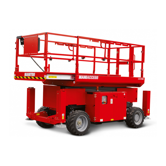
100 SC-2
120 SC-2
140 SC
OPERATOR'S MANUAL
(ORIGINAL INSTRUCTIONS)
Table of
Contents
Previous
Page
Next
Page
1
2
3
4
5
Advertisement
Chapters
Section 1
7
Section 2
37
Section 3
75
Table of Contents
Need help?
Do you have a question about the 100 SC-2 and is the answer not in the manual?
Ask a question
Questions and answers
Related Manuals for Manitou 100 SC-2
Lifting Systems Manitou MHT 10180 LT-E3 Operator's Manual
(224 pages)
Lifting Systems Manitou MHT 10225 LT-E3 Operator's Manual
(224 pages)
Lifting Systems Manitou 150 AETJ C Operator's Manual
Access platform (102 pages)
Lifting Systems Manitou 150 AETJ C Operator's Manual
(100 pages)
Lifting Systems Manitou 150 AETJ Operator's Manual
(134 pages)
Lifting Systems Manitou 150 AETJ C Instruction Sheet
(2 pages)
Lifting Systems Manitou 160 ATJ PLUS Euro 3 Operator's Manual
(142 pages)
Lifting Systems Manitou 140 SC Operator's Manual
(104 pages)
Lifting Systems Manitou 105 VJR 2 Operator's Manual
(70 pages)
Lifting Systems Manitou PRIVILEGE MRT 1850 PLUS-E3 Use Manual
Baskets (166 pages)
Lifting Systems Manitou MI 80 D ST4 S2 Operator's Manual
(98 pages)
Lifting Systems Manitou MT 728 Operator's Manual
C-e2 series; 3-e2 series (138 pages)
Lifting Systems Manitou 260 TJ Operator's Manual
(188 pages)
Lifting Systems Manitou MHT 7140 T-E3 Operator's Manual
(224 pages)
Lifting Systems Manitou TMT 25 I 2-E3 Series Operator's Manual
(140 pages)
Lifting Systems Manitou 220TJ Operator's Manual
(164 pages)
This manual is also suitable for:
120 sc-2
140 sc
Table of Contents
Print
Rename the bookmark
Delete bookmark?
Delete from my manuals?
Login
Sign In
OR
Sign in with Facebook
Sign in with Google
Upload manual
Upload from disk
Upload from URL


Need help?
Do you have a question about the 100 SC-2 and is the answer not in the manual?
Questions and answers