Table of Contents
Advertisement
INTRODUCTION TO SAFETY
THIS OPERATOR'S MANUAL MUST BE KEPT IN THE LIFT TRUCK AND MUST BE READ AND UNDERSTOOD BY OPERATORS.
MANITOU NORTH AMERICA, INC.
6401 IMPERIAL DRIVE
WACO, TX 76712-6803
For Parts Orders contact your Manitou North America Dealer or call:
Manitou North America, Inc. Parts Dept. (800) 425-3727 or (254) 799-0232
Parts Dept. Fax (254) 867-6504 Website: www.manitou-na.com
547973AS (11/10)
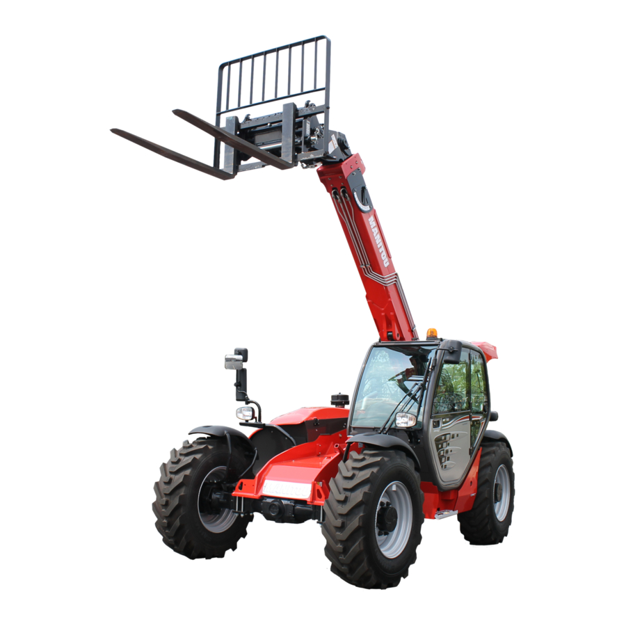
MT 728 Série C-E2
MT 732 Série C-E2 (USA)
MT 732 Turbo Série C-E2
MT 928 Série C-E2
MT 932 Série C-E2
MT 932 Turbo Série C-E2
MT 1030 S Série 3-E2
MT 1030 S Turbo Série 3-E2
OPERATOR'S MANUAL
Advertisement
Chapters
Table of Contents


Need help?
Do you have a question about the MT 728 and is the answer not in the manual?
Questions and answers