
Related Manuals for Manitou TMT 25 I 2-E3 Series


Summary of Contents for Manitou TMT 25 I 2-E3 Series
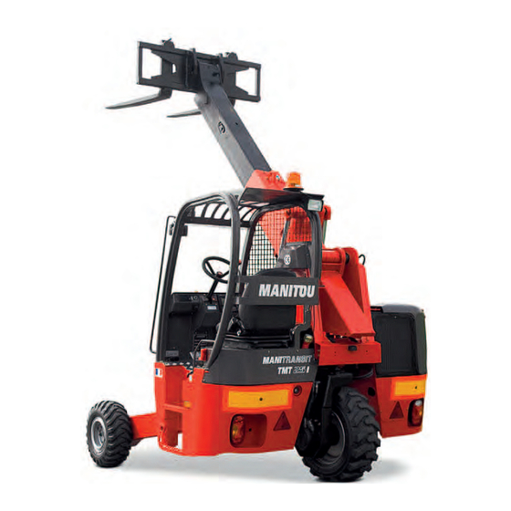
- Page 1 647186 EN (20/02/2017) TMT 25 I Série 2-E3 TMT 25 S Série 2-E3 TMT 27 S Série 2-E3 TMT 27 P Série 2-E3 TMT 25 P Série 2-E3 TMT 25 S 4W Série 2-E3 OPERATOR'S MANUAL (ORIGINAL INSTRUCTIONS)
- Page 2 - Descriptions and figures are non binding. - MANITOU reserves the right to change its models and their equipment without being required to update this manual. - The MANITOU network, consisting exclusively of qualified professionals, is at your disposal to answer all your questions.
- Page 3 MANITOU BF. Any violation of the aforementioned may lead to civil and criminal prosecution. The logos as well as the visual identity of the company are the property of MANITOU BF and may not be...
- Page 4 1 - OPERATING AND SAFETY INSTRUCTIONS 2 - DESCRIPTION 3 - MAINTENANCE 4 - OPTIONAL ATTACHMENTS FOR USE WITH THE RANGE...
-
Page 5: Operating And Safety Instructions
1 - O P E R A T I N G A N D S A F E T Y INSTRUCTIONS 1 - 1... - Page 6 1 - 2...
- Page 7 1 - 3...
-
Page 8: Table Of Contents
TABLE OF CONTENTS 1 - OPERATING AND SAFETY INSTRUCTIONS INSTRUCTIONS TO THE COMPANY MANAGER THE SITE THE OPERATOR THE LIFT TRUCK A - THE TRUCK'S SUITABILITY FOR THE JOB ..........6 B - ADAPTATION OF THE LIFT TRUCK TO STANDARD ENVIRONMENTAL CONDITIONS . - Page 9 LIFT TRUCK MAINTENANCE INSTRUCTIONS GENERAL INSTRUCTIONS MAINTENANCE LUBRICANT AND FUEL LEVELS HYDRAULICS ELECTRICITY WELDING WASHING THE LIFT TRUCK TRANSPORTING THE LIFT TRUCK IF THE LIFT TRUCK IS NOT TO BE USED FOR A LONG TIME INTRODUCTION PREPARING THE LIFT TRUCK PROTECTING THE ENGINE PROTECTING THE LIFT TRUCK BRINGING THE LIFT TRUCK BACK INTO SERVICE...
-
Page 10: Instructions To The Company Manager
A - THE TRUCK'S SUITABILITY FOR THE JOB - MANITOU has ensured that this lift truck is suitable for use under the standard operating conditions defined in this operator's manual, with a STATIC TEST COEFFICIENT 1.33 and a DYNAMIC TEST COEFFICIENT OF 1, as specified in harmonized norm EN 1459 for mast trucks. -
Page 11: C - Modification Of The Lift Truck
as well as the cab suspension. Inflate the tyres in accordance with recommendations. • Ensure that the operators adapt their operating speed to suit the conditions on site. • As far as possible, arrange the site in such a way as to provide a flat running surface and remove obstacles and harmful potholes. -
Page 12: Instructions For The Operator
- At any time, as an operator, you must envisage, within reason, the possible risk to yourself, to others or to the lift truck itself when you use it. IMPORTANT In order to reduce or avoid any danger with a MANITOU-approved attachment, follow the instructions of paragraph: 4 - ADAPTABLE ATTACHMENTS AVAILABLE ON THE RANGE: INTRODUCTION. GENERAL INSTRUCTIONS A - INSTRUCTION MANUAL - Read the operator's manual carefully. -
Page 13: E - Lifting People
• or authorized exceptionally and under certain conditions (see current regulations in the country in which the lift truck is used). - MANITOU sells equipment specifically designed for lifting people (OPTION PLATFORM lift truck, contact your dealer). F - REAR OF VEHICLE ATTACHMENT SYSTEM - Optional solutions exist, please consult your dealer. -
Page 14: Operating Instructions Unladen And Laden
OPERATING INSTRUCTIONS UNLADEN AND LADEN A - BEFORE STARTING THE LIFT TRUCK - Carry out daily maintenance ( MAINTENANCE: 10H - DAILY MAINTENANCE). - Make sure that the driver's cab is clean, particularly the floor and floor mat. Check that no movable object may hinder the operation of the lift truck. -
Page 15: D - Visibility
- Never stack loads on uneven ground, they may tip over. IMPORTANT If the load or the attachment must remain above a structure for a long time, there is the risk that it will rest on the structure because of the boom descending owing to the oil in the cylinders cooling down. -
Page 16: F - Driving The Lift Truck
- Check all control instruments when the engine is warm and at regular intervals during use, so as to quickly detect any faults and to be able to correct them without any delay. - If an instrument does not show the correct display, stop the engine and immediately carry out the necessary operations. F - DRIVING THE LIFT TRUCK SAFETY INSTRUCTIONS IMPORTANT... -
Page 17: G - Stopping The Lift Truck
G - STOPPING THE LIFT TRUCK SAFETY INSTRUCTIONS - Never leave the ignition key in the lift truck during the operator's absence. - When the lift truck is stationary, or if the operator has to leave his cab (even for a moment), place the forks or attachment on the ground, apply the parking brake and place the forward/reverse selector in neutral. - Page 18 DRIVING THE LIFT TRUCK WITH A FRONT-MOUNTED ATTACHMENT - You must comply with current regulations in your country, covering the possibility of driving on the public highway with a front-mounted attachment on your lift truck. - If road legislation in your country authorizes circulation with a front-mounted attachment, you must at least: •...
-
Page 19: Instructions For Handling A Load
INSTRUCTIONS FOR HANDLING A LOAD A - CHOICE OF ATTACHMENTS - Only attachments approved by MANITOU can be used on its lift trucks. - Make sure the attachment is appropriate for the work to be done ( ADAPTABLE ATTACHMENTS AVAILABLE ON THE RANGE). -
Page 20: D - Transverse Attitude Of The Lift Truck
D - TRANSVERSE ATTITUDE OF THE LIFT TRUCK The transverse attitude is the transverse slope of the frame with respect to the horizontal. Raising the boom reduces the lift truck's lateral stability. The transverse attitude must be set with the boom in the down position as follows: 1 - LIFT TRUCK WITHOUT ROLL CORRECTOR USED ON TYRES - Position the lift truck so that the bubble in the level is between the two lines ( DESCRIPTION: CONTROL AND COMMAND... -
Page 21: F - Taking Up And Laying A High Load On Tyres
F - TAKING UP AND LAYING A HIGH LOAD ON TYRES IMPORTANT You must not raise the boom if you have not checked the transverse attitude of the lift truck ( INSTRUCTIONS FOR HANDLING A LOAD: D - TRANSVERSE ATTITUDE OF THE LIFT TRUCK). REMINDER: Make sure that the following operations can be performed with good visibility ( OPERATION INSTRUCTIONS UNLADEN AND LADEN:... - Page 22 LAYING A HIGH LOAD ON TYRES - Approach the load in the transport position in front of the stack (fig. F6). - Apply the parking brake and place the forward/reverse selector in neutral. - Raise and extend the boom (1) (2) until the load is above the stack, while monitoring the longitudinal stability limiter and warning device ( INSTRUCTIONS FOR HANDLING A LOAD: C - LONGITUDINAL STABILITY LIMITER AND WARNING DEVICE).
-
Page 23: G - Taking Up And Setting Down A High Load On Stabilisers
G - TAKING UP AND SETTING DOWN A HIGH LOAD ON STABILISERS Depending on the model of lift truck IMPORTANT You must not raise the boom if you have not checked the transverse attitude of the lift truck ( INSTRUCTIONS FOR HANDLING A LOAD: D - TRANSVERSE ATTITUDE OF THE LIFT TRUCK). REMINDER: Make sure that the following operations can be performed with good visibility ( OPERATION INSTRUCTIONS UNLADEN AND LADEN: D - VISIBILITY). - Page 24 TAKING UP A HIGH LOAD ON STABILISERS - Ensure that the forks will easily pass under the load. - Check the position of the lift truck with respect to the load and make a test run, if necessary, without taking the load. - Raise and extend the boom (1) (2) until the forks are at the level of the load (fig.
-
Page 25: H - Picking Up And Setting Down A Suspended Load
H - PICKING UP AND SETTING DOWN A SUSPENDED LOAD IMPORTANT WARNING: Failure to follow the above instructions may lead the lift truck to loose stability and overturn. MUST be used with a lift truck equipped with an operational hydraulic movement cut-off device. CONDITIONS OF USE - The length of the sling or the chain shall be as short as possible to limit swinging of the load. - Page 26 LIFT TRUCK MAINTENANCE INSTRUCTIONS GENERAL INSTRUCTIONS - Ensure the area is sufficiently ventilated before starting the lift truck. - Wear clothes suitable for the maintenance of the lift truck, avoid wearing jewelery and loose clothes. Tie and protect your hair, if necessary. - Stop the engine and remove the ignition key, when an intervention is necessary.
- Page 27 WELDING - Disconnect the battery before any welding operations on the lift truck. - When carrying out electric welding work on the lift truck, connect the negative cable from the equipment directly to the part being welded, so as to avoid high tension current passing through the alternator. - Never carry out welding or work which gives off heat on an assembled tyre.
- Page 28 IF THE LIFT TRUCK IS NOT TO BE USED FOR A LONG TIME INTRODUCTION The following recommendations are intended to prevent the lift truck from being damaged when it is withdrawn from service for an extended period. IMPORTANT Procedures to follow if the lift truck is not to be used for a long time and for starting it up again afterwards must be performed by your dealership. This long-term storage period must not exceed 12 months.
- Page 29 • Glass items can be removed and collected for processing by glaziers. ENVIRONMENTAL PROTECTION By entrusting the maintenance of your lift truck to the MANITOU network, the risk of pollution is limited and the contribution to environmental protection contribution is made.
- Page 30 1 - 26...
- Page 31 2 - DESCRIPTION...
- Page 33 2 - DESCRIPTION CE DECLARATION OF CONFORMITY SAFETY PLATES AND STICKERS IDENTIFICATION OF THE LIFT TRUCK CHARACTERISTICS TMT 25 I S2-E3 2-10 DIMENSIONS AND LOAD CHARTS TMT 25 I S2-E3 2-12 CHARACTERISTICS TMT 25 S S2-E3 2-14 DIMENSIONS AND LOAD CHARTS TMT 25 S S2-E3 2-16 CHARACTERISTICS...
- Page 34 430, rue de l’Aubinière - BP 10249 - 44158 - ANCENIS CEDEX - FRANCE Dossier technique, Technical file MANITOU BF - 430, rue de l’Aubinière BP 10249 - 44158 - ANCENIS CEDEX - FRANCE Constructeur de la machine décrite ci-après, Manufacturer of the machine described below TMT 25 I Série 2-E3...
- Page 35 bg : 1) удостоверение за « СЕ » съответствие (oригинална), 2) Фирмата, 3) Адрес, 4) Техническо досие, 5) Фабрикант на описаната по-долу машина, 6) Обявява, че тази машина, 7) Отговаря на следните директиви и на тяхното съответствие национално право, 8) За машините към допълнение IV, 9)Номер на удостоверението, 10) Наименувана фирма, 15) хармонизирани...
- Page 36 SAFETY PLATES AND STICKERS IMPORTANT Clean all of the stickers and safety plates to make them legible. It is essential to replace stickers and safety plates which are illegible or damaged. Check the presence of stickers and safety plates after replacing any spare parts. EXTERNAL PLATES AND STICKERS ITEM PART NO.
- Page 37 ITEM PART NO. DESCRIPTION 300681 - Instructions prior to start-up 574317 - Unladen travel safety instruction 721744 - Manipulator function 76571 - Forward/reverse selector 234798 - Hydraulic oil filling 239594 - Sound power level 104db 234806 - Differential lock 255934 - Safety instruction 733846 - Steering mode _ TMT 25S 4W...
- Page 38 CHARACTERISTICS for all other technical information relating to your lift truck. ENGINE • Model • Serial No. • Engine No. TRANSMISSION • Type of transmission • MANITOU part no. • Serial No. FRONT WHEEL REDUCING GEAR TMT .. TMT .. 4W • Type • Code...
- Page 39 REAR WHEEL REDUCING GEAR • Type • Code • Serial No. BOOM • MANITOU part no. • Date of manufacture CONNECTION MANUFACTURER'S PLATE • Model MANITOU BF 44158 ANCENIS CEDEX • Serial No. FRANCE MODELE • Year of manufacture N° dans la série Année fabrication...
- Page 40 CHARACTERISTICS TMT 25 I S2-E3 ENGINE Type KUBOTA V2403 M E3B 1J476-27000 Fuel Diesel Number of cylinders 4 in line Suction Natural Injection system Mechanical Ignition sequence 1.3.4.2 Capacity 2434 Bore and stroke 87 x 102,4 Compression ratio 23/1 Nominal speed laden 2700 Min.
- Page 41 HYDRAULIC CIRCUIT Hydraulic pump CASAPPA Gear pump with flow splitter + direction Type change 1st casing 2nd casing Capacity Max. rating capacity unladen l/mn Flow rate at 1600 rpm l/mn Filtration Return μm Suction μm Maximum service pressure Telescoping circuit 200 / 270 Lifting circuit 275 / 270...
- Page 42 DIMENSIONS AND LOAD CHARTS TMT 25 I S2-E3 1200 (mm) 1783 (mm) (mm) (mm) (mm) 1550 (mm) 1541 (mm) 1408 (mm) 2750 (mm) 2413 (mm) 3083 (mm) 3102 (mm) (mm) -132 (mm) 3363 (mm) (mm) 1270 (mm) 1270 (mm) 1634 (mm) (mm) (mm)
- Page 43 2-13...
- Page 44 CHARACTERISTICS TMT 25 S S2-E3 ENGINE Type KUBOTA V2403 M E3B 1J476-27000 Fuel Diesel Number of cylinders 4 in line Suction Natural Injection system Mechanical Ignition sequence 1.3.4.2 Capacity 2434 Bore and stroke 87 x 102,4 Compression ratio 23/1 Nominal speed laden 2700 Min.
- Page 45 HYDRAULIC CIRCUIT Hydraulic pump CASAPPA Gear pump with flow splitter + direction Type change 1st casing 2nd casing Capacity Max. rating capacity unladen l/mn Flow rate at 1600 rpm l/mn Filtration Return μm Suction μm Maximum service pressure Telescoping circuit 200 / 270 Lifting circuit 275 / 270...
- Page 46 DIMENSIONS AND LOAD CHARTS TMT 25 S S2-E3 1200 (mm) 1651 (mm) (mm) (mm) (mm) 1583 (mm) 1532 (mm) 1416 (mm) 2783 (mm) 2478 (mm) 3198 (mm) 2072 (mm) (mm) (mm) 3415 (mm) (mm) 1270 (mm) 1270 (mm) 1520 (mm) (mm) (mm) (mm)
- Page 47 2-17...
- Page 48 CHARACTERISTICS TMT 27 S S2-E3 ENGINE Type KUBOTA V2403 M E3B 1J476-27000 Fuel Diesel Number of cylinders 4 in line Suction Natural Injection system Mechanical Ignition sequence 1.3.4.2 Capacity 2434 Bore and stroke 87 x 102,4 Compression ratio 23/1 Nominal speed laden 2700 Min.
- Page 49 HYDRAULIC CIRCUIT Hydraulic pump CASAPPA Gear pump with flow splitter + direction Type change 1st casing 2nd casing Capacity Max. rating capacity unladen l/mn Flow rate at 1600 rpm l/mn Filtration Return μm Suction μm Maximum service pressure Telescoping circuit 200 / 270 Lifting circuit 275 / 270...
- Page 50 DIMENSIONS AND LOAD CHARTS TMT 27 S S2-E3 1200 (mm) 1921 (mm) (mm) (mm) (mm) 1583 (mm) 1532 (mm) 1416 (mm) 2783 (mm) 2746 (mm) 3198 (mm) 2072 (mm) (mm) (mm) 3415 (mm) (mm) 1270 (mm) 1270 (mm) 1520 (mm) (mm) (mm) (mm)
- Page 51 2-21...
- Page 52 CHARACTERISTICS TMT 27 P S2-E3 ENGINE Type KUBOTA V2403 M E3B 1J476-27000 Fuel Diesel Number of cylinders 4 in line Suction Natural Injection system Mechanical Ignition sequence 1.3.4.2 Capacity 2434 Bore and stroke 87 x 102,4 Compression ratio 23/1 Nominal speed laden 2700 Min.
- Page 53 HYDRAULIC CIRCUIT Hydraulic pump CASAPPA Gear pump with flow splitter + direction Type change 1st casing 2nd casing Capacity Max. rating capacity unladen l/mn Flow rate at 1600 rpm l/mn Filtration Return μm Suction μm Maximum service pressure Telescoping circuit 200 / 270 Lifting circuit 280 / 270...
- Page 54 DIMENSIONS AND LOAD CHARTS TMT 27 P S2-E3 1200 (mm) 1921 (mm) (mm) (mm) (mm) 1583 (mm) 1520 (mm) 1416 (mm) 2783 (mm) 2734 (mm) 3233 (mm) 2072 (mm) (mm) (mm) 3403 (mm) (mm) 1270 (mm) 1270 (mm) 1520 (mm) (mm) (mm) (mm)
- Page 55 TMT27P 40° 50° 0.5m 30° 3,40 20° 10° 0° -10° -20° -30° 0.95 0,35 1.11 0,65 -40° -50° SUIVANT NORME EN 1459 annexe B. N°296305 TMT27P 40° 50° 0.6m 30° 3,40 20° 10° 0° -10° -20° -30° 0.95 0,35 0,65 1.21 -40°...
- Page 56 CHARACTERISTICS TMT 25 P S2-E3 ENGINE Type KUBOTA V2403 M E3B 1J476-27000 Fuel Diesel Number of cylinders 4 in line Suction Natural Injection system Mechanical Ignition sequence 1.3.4.2 Capacity 2434 Bore and stroke 87 x 102,4 Compression ratio 23/1 Nominal speed laden 2700 Min.
- Page 57 HYDRAULIC CIRCUIT Hydraulic pump CASAPPA Gear pump with flow splitter + direction Type change 1st casing 2nd casing Capacity Max. rating capacity unladen l/mn Flow rate at 1600 rpm l/mn Filtration Return μm Suction μm Maximum service pressure Telescoping circuit 200 / 270 Lifting circuit 280 / 270...
- Page 58 DIMENSIONS AND LOAD CHARTS TMT 25 P S2-E3 1200 (mm) 1921 (mm) (mm) (mm) (mm) 1583 (mm) 1520 (mm) 1416 (mm) 2783 (mm) 2734 (mm) 3233 (mm) 2072 (mm) (mm) (mm) 3403 (mm) (mm) 1270 (mm) 1270 (mm) 1520 (mm) (mm) (mm) (mm)
- Page 59 2-29...
- Page 60 CHARACTERISTICS TMT 25 S 4W S2-E3 Manufacturer MANITOU Model type TMT25S 4W Propulsion: battery, diesel, petrol, LPG, mains Diesel Type of operation: manual, pedestrian, standing, seated Seated Rated capacity / load on forks (basic capacity) Q (t) Center of gravity of load...
- Page 61 Speed of travel laden km/h 5.1.1 Speed of travel unladen km/h Rate of lift (laden) 0,38 5.2.1 Rate of lift (unladen) 0,41 Speed of lowering laden 0,46 5.3.1 Speed of lowering unladen 0,55 Nominal towing power laden 18000 5.5.1 Nominal towing power unladen 7400 Slope laden 5.7.1...
- Page 62 LOAD CHARTS TMT 25 S 4W S2-E3 2-32...
- Page 63 2-33...
- Page 64 TYRES PRESSURE LOAD PER TYRE (kg) TMT 25 I S2-E3 FRONT UNLADEN FRONT LADEN REAR UNLADEN REAR LADEN (bar) HAULER 18x7-8 16PR 1550 CONTINENTAL 23x9-10 14PR IC 30 SOLIDEAL 10-16,5 10PR SKS XTRA TUBELESS 1700 1850 PRESSURE LOAD PER TYRE (kg) TMT 25 S S2-E3 FRONT UNLADEN FRONT LADEN...
- Page 65 GROUND CONTACT PRESSURE (kg/ PRESSURE GROUND CONTACT AREA (cm2) LOAD (kg) cm2) (bar) HARD GROUND SOFT GROUND HARD GROUND SOFT GROUND 5,79 1,88 HAULER 18x7-8 16PR 1550 7,79 2,50 6,78 3,53 6,80 3,56 1550 8,32 4,13 1650 8,47 4,17 SOLIDEAL 10-16,5 10PR SKS XTRA TUBELESS 1700 8,53...
- Page 66 INSTRUMENTS AND CONTROLS DESCRIPTION 1 - DRIVER'S SEAT 2 - SEAT BELT 3 - INTERFACE SCREEN 4 - FUEL LEVEL AND HOUR METER 5 - LONGITUDINAL STABILITY LIMITER AND WARNING DEVICE 6 - SWITCH PANEL 7 - DIFFERENTIAL LOCK PEDAL 8 - IGNITION SWITCH 9 - HORN 10 - LEVEL INDICATOR...
- Page 67 2-37...
- Page 68 1 - DRIVER'S SEAT DRIVER’S SEAT (STANDARD) DESIGNED FOR MAXIMUM COMFORT, THIS SEAT CAN BE ADJUSTED AS FOLLOWS. LONGITUDINAL ADJUSTMENT - Pull the locking lever 1 upwards. - Slide the seat assembly to achieve a good driving position. - Release the lever and be sure it returns to the lock position. SEAT SUSPENSION ADJUSTMENT - Pull and lift up the locking lever 2 so as to place it into one of these five positions.
- Page 69 LUMBAR ADJUSTMENT (FIG. C) This increases the comfort of the seat and the driver’s freedom of movement. - Turn knob to 1 to adjust the height and depth of the lumbar support of the upper part of the back-rest. - Turn knob to 2 to adjust the height and depth of the lumbar support of the lower part of the back-rest.
- Page 70 3 - INTERFACE SCREEN INTERFACE SCREEN This screen displays all the start-up, configuration and maintenance stages, as well as lift truck faults. NOTE: The current system time is displayed at the bottom of each page. SCREEN DATA VALIDATION KEYS These keys serve to navigate within the program and to validate the different screen data.
- Page 71 5 - LONGITUDINAL STABILITY LIMITER AND WARNING DEVICE This device warns the operator of the lift truck's longitudinal stability limits. However, lateral stability can reduce the load chart in the upper part, and this reduction is not detected by the longitudinal stability limiter and warning device. IMPORTANT The operator must respect the lift truck's load chart.
- Page 72 6 - SWITCH PANEL A - WHITE FRONT WORKING LIGHT(S) BLUE FRONT WORKING LIGHT(S) (OPTION) • Position A1: White working lights • Position A2: Working lights off • Position A3: Blue working lights option B - HAZARD WARNING LIGHTS (OPTION) This switch enables the L.H.
- Page 73 - Indicator D1 will appear, indicating that the "aggravating" hydraulic movement cut-off is disabled. Warning D2 will also appear, indicating, close to the longitudinal stability warning device, that hydraulic movement cut-off is disabled. - Perform the boom retraction de-aggravating hydraulic movement with extreme caution. IMPORTANT Remain very vigilant during this operation.
- Page 74 7 - DIFFERENTIAL LOCK PEDAL IMPORTANT While the differential lock is engaged, always drive in a straight line and at low speed. The differential lock allows the driving wheels to rotate at the same speed regardless of ground conditions. Fully depress pedal 1 to engage. Hold this position for as long as the differential lock is required.
- Page 75 11 - FUSES AND RELAYS IMPORTANT Always replace a faulty fuse with another of equivalent rating. Never use a fuse that has been repaired. ENGINE COMPARTMENT - Remove cover 1 in order to gain access to the fuses and relays. RELAYS K1 to K9 •...
- Page 76 RELAYS K10 to K18 F22 F23 • K10 - "Movement authorisation" time delay relay. • K11 - "Movement cut-off and speed reducer switch" self-maintaining relay. • K12 - Cut-off bypass relay. • K13 - Not used. • K14 - Overload relay. •...
- Page 77 15 - FORWARD/REVERSE SELECTOR When changing the direction of travel, the lift truck should be traveling at slow speed and not accelerating. • FORWARD: Push the switch forward (position A). • REVERSE: Pull the knob backwards (position B). • NEUTRAL: The switch must be in the neutral position (position C) to start the lift truck.
- Page 78 17 - REAR LIGHTS Works only in the rear of lorry or trailer transport position. • A - Rear left indicator light. • B - Left rear stoplight. • C - Left rear headlight. • D - Rear fog light. •...
- Page 79 2-49...
- Page 80 EXAMPLE OF SCREEN DISPLAY 1 - START-UP PAGE When the power is switched on, an initialisation page A1 appears on the screen. This page remains displayed during the CAN - management computer dialogue phases and the overload test phase. Reseau CAN 2 - WORKING PAGE Working page A2 is displayed as soon as the start-up phase is completed.
- Page 81 SIGNAL LIGHTS I - FOG LIGHT INDICATOR LAMP (ROAD LIGHT OPTION) J - ROTATING BEACON LIGHT (OPTION) K - DIRECTION INDICATOR INDICATOR LAMP (ROAD LIGHT OPTION) 1550.0 1 1 : 0 2 SCREEN CONTRAST Pressing button F4 changes the screen brightness/contrast mode (M). Daytime mode Daytime-Night-time mode Night-time mode...
- Page 82 INFORMATION ZONE P - SCROLLING INFORMATION ZONE DATA Pressing key P will scroll through the data in the information zone. 1550.0 1550.0 • Engine hours • Time to next scheduled maintenance 1 1 : 0 2 1595 • Engine speed 15.5 •...
- Page 83 B - “SECRET CODE” PAGE The secret code page allows a code to be entered in order to obtain a different access level. In the event that the incorrect code is entered, the current access level will return to the operator level. Select a number using keys F1 or F2 and validate with F4.
- Page 84 E - “SENSOR / ACTUATOR” PAGE The sensor / actuator display pages show the status of the system’s different analog and digital inputs and outputs. Use keys F1 or F2 to change the current page, with an indication of the total number of pages (e.g.: page E1).
- Page 85 G - “TREE STRUCTURE / CODIFICATION” PAGE Page G1 displays all the codes of the computers present on the network. • 1 - Computer (engine housing) • 2 - Screen interface unit • 3 - Computer (not used) (An ERR message is displayed when the computer is not detected). The codification detail page G2 displays the codes of a specific computer.
- Page 86 4 - MAINTENANCE PAGE Maintenance page A gives access to 2 maintenance sub-menus: The secret code entered determines the level of access to parameters for viewing or modification. • CODE 0000 or 1000: MAINTENANCE: OVERLOAD TEST • CODE (dealer access level): MAINTENANCES OVERLOAD TEST OVERLOAD CALIBRATION...
- Page 87 B - OVERLOAD TEST PAGE This page allows the periodic checking of overload sensor operation and adjustment ( 3 - MAINTENANCE: A - LONGITUDINAL STABILITY LIMITER AND WARNING DEVICE) 2-57...
- Page 88 DESCRIPTION AND USE OF THE OPTIONS 1 - FRONT HEADLIGHTS (ROAD LIGHT OPTION) • A - Front left indicator light. • B - Left front dipped beam headlight. • C - Left front main beam. • D - Left front sidelight. •...
- Page 89 6 - REVERSING BUZZER ALARM To deactivate this option, SCREEN DISPLAY - DESCRIPTION OF PAGES : 3 - MENU PAGE (F - MACHINE PARAMETER PAGE). 7 - REVERSING LIGHT 8 - QUICK-RELEASE COUPLER ON ATTACHMENT CIRCUIT 9 - MANUAL FOLDING LOAD CARRIER (OPTION) TMT 25 S 4W Série 2-E3 The load carrier allows a load to, be set down on the folding arms in order to stabilise it while the lift truck is moving.
- Page 90 10 - HYDRAULIC FOLDING LOAD CARRIER (OPTION) TMT 25 S 4W Série 2-E3 The load carrier allows a load to, be set down on the folding arms in order to stabilise it while the lift truck is moving. IMPORTANT The load carrier arms must be in the folded-down position (position B) when attaching the lift truck to the rear of the lorry or trailer.
- Page 91 2-61...
- Page 92 PROCEDURE FOR ATTACHING THE LIFT TRUCK TO THE REAR OF A LORRY OR TRAILER 1 - INSTALLING THE LIFT TRUCK ONTO THE BACK OF THE LORRY OR TRAILER 2 - LOWERING THE LIFT TRUCK FROM THE BACK OF THE LORRY OR TRAILER IDENTIFICATION OF DISTRIBUTOR LEVERS •...
- Page 93 1 - INSTALLING THE LIFT TRUCK AT THE BACK OF THE LORRY OR TRAILER PREPARING THE TRAILER: - Apply the lorry parking brake. - Move the trailer lights (fig. 1A and 1B). - Retract the underrun guards (fig. 1C). (Trailer light protection) INSTALLING THE LIFT TRUCK ON THE TRAILER: - Adjust the spacing and center the forks on the lift truck carriage (identical spacing to that of the lorry sockets).
- Page 94 FOR A CHAIN-BASED ATTACHMENT SYSTEM - Tilt the lift truck forward by pulling back on distributor lever - Attach the two chains 7 (fig. 1G) and 8 (fig. 1H) to the lorry’s clevis fittings 9. Block the clevis pins 10 (fig. 1G and fig. 1H) with the locking pins. - Pull back distributor lever A to tension the chains.
- Page 95 2 - LOWERING THE LIFT TRUCK FROM THE BACK OF THE LORRY OR TRAILER - Apply the lorry parking brake. - Unhook the strap (fig. 2A) (only applies to the telescopic support attachment system). - Disconnect the lorry light supply plugs 11 and 12 and place them on their support on the lift truck (fig.
- Page 96 FOR A CHAIN-BASED ATTACHMENT SYSTEM - Push distributor lever A forwards to slacken the two chains. - Remove the locking pins from the clevis pins 10 (fig. 2E and fig. 2F). Unhook the two chains 7 (fig. 2E) and 8 (fig. 2F) from the lorry’s clevis fittings 9. - Lower the lift truck by pulling back on distributor lever A.
- Page 97 3 - MAINTENANCE 3 - 1...
- Page 98 3 - MAINTENANCE ORIGINAL MANITOU SPARE PARTS AND EQUIPMENT FORKLIFT TRUCK MAINTENANCE DAILY AND WEEKLY MAINTENANCE MANDATORY FIRST 500 HOURS OR 6 MONTHS SERVICE PERIODIC MAINTENANCE OCCASIONAL MAINTENANCE AND OPERATION FILTERS CARTRIDGES AND BELTS LUBRICANTS AND FUEL 3-10 10H - DAILY MAINTENANCE OR EVERY 10 HOURS OF SERVICE...
- Page 99 • Efficient help with diagnosis. • Improvements due to experience feedback. • Operator training. • Only the MANITOU network has detailed knowledge of the design of the lift truck and therefore the best technical ability to provide maintenance. IMPORTANT ORIGINAL REPLACEMENT PARTS ARE DISTRIBUTED ONLY BY MANITOU AND THE DEALER NETWORK.
- Page 100 This schedule enables the operator to keep up with the periodic maintenance of the lift truck by notifying the total number of hours of operation and the date of the service performed by the professional approved by the MANITOU network.
- Page 101 MANDATORY FIRST 500 HOURS OR 6 MONTHS SERVICE FIRST 500 HOURS BEFORE THE FIRST 6 MONTHS - If the lift truck completes its first 500 hours of service before the first 6 months are up, carry out the mandatory service and the 500 hour periodic maintenance ( 500 HOUR - PERIODIC MAINTENANCE - EVERY 500 HOURS OF SERVICE) FIRST 6 MONTHS BEFORE THE FIRST 500 HOURS...
- Page 102 PERIODIC MAINTENANCE MAINTENANCE SCHEDULE 1000 H 1500 H 2000 H 500 H WHEN DUE FIRST 6 MONTHS FIRST 500 HOURS OR 2 YEARS OR 3 YEARS OR 4 YEARS MANDATORY SERVICE PERIODIC MAINTENANCE MANDATORY SERVICE MACHINE COUNTER DATE OF SERVICING 2500 H 3000 H 3500 H...
- Page 103 1000H - PERIODIC MAINTENANCE - EVERY 1000 HOURS OF SERVICE OR 2 YEARS ALSO PERFORM THE 500 HOUR PERIODIC MAINTENANCE OPERATIONS. - CHECK Safety belt............... 3-26 - CLEAN Fuel tank .
- Page 104 OCCASIONAL MAINTENANCE AND OPERATION OCCASIONAL MAINTENANCE - BLEED Fuel supply system ............. . 3-32 - REPLACE Wheels .
- Page 105 FILTERS CARTRIDGES AND BELTS 500H - PERIODIC MAINTENANCE - EVERY 500 HOURS OF SERVICE ENGINE OIL FILTER HYDRAULIC RETURN OIL FILTER CARTRIDGE Part number: 749613 Part number: 686237 FUEL FILTER ALTERNATOR BELT Part number: 748087 Part number: 292198 FUEL PRE-FILTER Part number: 272194 1000H - PERIODIC MAINTENANCE - EVERY 1000 HOURS OF SERVICE OR 2 YEARS ADD FILTER ELEMENTS OF PERIODIC MAINTENANCE OF 500 HOURS OF SERVICE.
- Page 106 USE THE RECOMMENDED LUBRICANTS AND FUEL: - For topping up, oils may not be miscible. - For oil changes, MANITOU oils are perfectly appropriate. DIAGNOSTIC ANALYSIS OF OILS If a service or maintenance contract has been organized with the dealer, a diagnostic analysis of engine, transmission and axle oils may be requested depending on the rate of use.
- Page 107 3 - 11...
- Page 108 10H - DAILY MAINTENANCE OR EVERY 10 HOURS OF SERVICE CHECK Lift truck environment Carry out a general inspection around the lift truck: - Fluid leaks or stains on the ground. - Additional objects on the lift truck and in the cabin. - Mounting and locking of the attachment.
- Page 109 CHECK Fuel level As far as possible, keep the fuel tank well filled in order to minimize condensation due to the atmospheric conditions. - Remove cap 1. - Fill the fuel tank with clean fuel ( LUBRICANTS AND FUEL), filtered through a strainer or a clean, lint free cloth, through filler port 2.
- Page 110 1 - Awaiting test. - Press OK to start. 2 - Place the lift truck on level ground. - Pick up a load and fully retract the telescope. - Press OK to confirm. 3 - Idling engine speed. - Extend the telescope until movement is cut-off. 4 - Idling engine speed.
- Page 111 NOTE: Every 10 hours during the first 50 hours, then a last time at 250 hours IMPORTANT If the lift truck is used in an abrasive environment (dust, sand, and coal.), use lubricating varnish (MANITOU P/N: 483536). Please contact your dealer.
- Page 112 50H - WEEKLY MAINTENANCE OR EVERY 50 HOURS OF SERVICE CHECK Alternator/fan/crankshaft belt tension IMPORTANT If the compressor belt has to be changed, check the tension again after the first 20 hours of operation. - Open the engine cover. - Check the belt for signs of wear and cracks, and change if necessary ( MAINTENANCE: FILTERS CARTRIDGES AND BELTS).
- Page 113 - If necessary, add oil ( LUBRICANTS AND FUEL). - Unscrew the thumbwheels 2 to lift the access panel 3. - Remove cap 4. - Add oil through filler port 5. - Put the cap 4 back. - Refit the access panel 3. NOTE: Always maintain the oil level at a maximum as cooling depends on the oil flowing through the tank.
- Page 114 30 mm from the cartridge wall. Cleaning is completed when there is no more dust on the cartridge. - Clean the cartridge seal surfaces with a damp, clean lint-free cloth and grease with a silicone lubricant (MANITOU part no.: 479292).
- Page 115 7 - Lubricator of the tilt cylinder head axle (1 lubricator). REAR WHEEL STEERING 8 - Lubricators of the rear wheel steering pivot pins (3 lubricators). 9 - Steering cylinder head axle lubricator (1 lubricator). - Remove the floor A. 10 - Lubricator of the steering cylinder foot axle (1 lubricator).
- Page 116 MANUAL FOLDING LOAD CARRIER (OPTION) TMT 25 S 4 W Série 2-E3 13 - Lubricators of the left and right arm pivot axles (8 lubricators). HYDRAULIC FOLDING LOAD CARRIER (OPTION) TMT 25 S 4 W Série 2-E3 14 - Lubricators of the left and right arm pivot pins (10 lubricators). 15 - Lubricator of the left and right arm cylinder foot axle (2 lubricators).
- Page 117 3 - 21...
- Page 118 CHECK Hydraulic oil MANITOU offers a hydraulic oil analysis kit which might make it possible to delay the recommended deadline in the periodic maintenance schedule (2000 hours). In this case we recommend an analysis of the hydraulic oil every 500 hours of service.
- Page 119 REPLACE Fuel filter IMPORTANT Prior to carrying out any work on the fuel supply system, check that the lift truck ignition is switched off to prevent any fuel leaks. Carefully clean the outside of the filter and its holder, to prevent dust from getting into the system. Tighten the oil filter by hand pressure only and lock the filter in place by a quarter turn.
- Page 120 REPLACE Alternator belt IMPORTANT If the alternator belt has to be changed, check the tension again after the first 20 hours of operation. - Open the engine cover. REMOVING THE BELT - Loosen screws 1 by two to three turns. - Swivel the alternator assembly so as to free belt 2.
- Page 121 3 - 25...
- Page 122 1000H - PERIODIC MAINTENANCE - EVERY 1000 HOURS OF SERVICE OR 2 YEARS ALSO PERFORM THE 500 HOUR PERIODIC MAINTENANCE OPERATIONS. CHECK Safety belt IMPORTANT In no event should the lift truck be used if the seat belt is defective (fixing, locking, cuts, tears, etc.). Repair or replace the seat belt immediately.
- Page 123 - Leave the safety cartridge in place. - Carefully clean the following parts with a damp, clean lint-free cloth. • The inside of the filter and cover. • The inside of the filter inlet hose. • The gasket surfaces in the filter and in the cover. - Check pipes and connections between the air filter and the engine and the connection and state of the clogging indicator on the filter.
- Page 124 CHECK Engine silent blocks * CHECK Engine speeds * CHECK Engine valve clearances * CHECK Condition of wheels and tyres * CHECK Boom pad wear * CHECK Speeds of hydraulic movements * CHECK Condition of hoses and flexible pipes * CHECK Condition of cylinders (leakage, rods) * CHECK...
- Page 125 3 - 29...
- Page 126 2000H - PERIODIC MAINTENANCE - EVERY 2000 HOURS OF SERVICE OR 4 YEARS ALSO PERFORM THE 500 HOUR AND 1000 HOUR PERIODIC MAINTENANCE OPERATIONS. CHECK Wheel nut tightening torques - Check the condition of the tyres, to detect cuts, blisters, wear, etc. - Check the tightening torque of the wheel nuts with a torque wrench.
- Page 127 CHECK Injection pump * CHECK Injectors * CHECK Radiator * CHECK Water pump and thermostat * CHECK Alternator and starter * CHECK Hydrostatic transmission circuit pressures * CHECK Hydrostatic transmission control flow * CHECK Hydrostatic transmission cut-off operation * CHECK Steering * CHECK Front wheel...
- Page 128 OCCASIONAL MAINTENANCE BLEED Fuel supply system These operations are to be carried out only in the following cases: • A component of the fuel system replaced or drained. • A drained tank. • Running out of fuel. Ensure that the level of fuel in the tank is sufficient and bleed in the following order: BLEEDING THE FUEL FILTER - Open the engine cover.
- Page 129 FRONT WHEEL TMT 25 I - TMT 25 P For this operation, we advise you to use the hydraulic jack (MANITOU Part number 505507). - Immobilize the lift truck in both directions by blocking the wheel opposite the wheel to be changed.
- Page 130 RESET Longitudinal stability limiter and warning device This procedure may be necessary when checking a device setting ( 3 - MAINTENANCE: A6 - LONGITUDINAL STABILITY LIMITER AND WARNING DEVICE). Also, according to the use of the lift truck, the device may require to be periodically reset. This function can only be accessed with a "dealer"...
- Page 131 3 - 35...
- Page 132 OCCASIONAL OPERATION Lift truck IMPORTANT If the lift truck is not on level ground, chock it so that it does not descend the slope. The lift truck must be towed very slowly (less than 5 km/h) and for as short a distance as possible (less than 100 m). For towing a lift truck, the high pressure limiters must be unlocked to avoid damaging the hydrostatic transmission, and the parking brake on the front axle must be released.
- Page 133 TRANSPORT Lift truck IMPORTANT Before the loading of the lift truck: - Ensure that the platform safety instructions are correctly applied. - Ensure that the transporter is informed of the lift truck dimensions and weight characteristics ( 2 - DESCRIPTION: CHARACTERISTICS). - Ensure that the platform is of sufficient size and load capacity for transporting the lift truck.
- Page 134 3 - 38...
- Page 135 4 - OPTIONAL ADAPTABLE ATTACHMENTS FOR THE RANGE 4 - 1...
- Page 136 TABLE OF CONTENTS 4 - OPTIONAL ADAPTABLE ATTACHMENTS FOR THE RANGE INTRODUCTION TECHNICAL SPECIFICATIONS OF ATTACHMENTS ATTACHMENT GUARDS 4 - 2...
- Page 137 INTRODUCTION - Your lift truck must be used with interchangeable equipment. These items are called: ATTACHMENTS. - A wide range of attachments is available, guaranteed by MANITOU and designed to fit your lift truck perfectly. IMPORTANT Only attachments approved by MANITOU are to be used on our lift trucks (see: 4 - ADAPTABLE ATTACHMENTS IN OPTION ON THE RANGE: TECHNICAL SPECIFICATIONS OF ATTACHMENTS).
- Page 138 TECHNICAL SPECIFICATIONS OF ATTACHMENTS STANDARDIZED FORK PART NO. 415565 289049 415253 Section 125x40x1100 mm 125x40x1200 mm 125x40x1400 mm Weight 54 kg 56 kg 70 kg PART NO. 486520 Section 125x45x2000 mm Weight 104 kg LOAD BACK REST PART NO. 733901 Width 1270 mm Height...
- Page 139 ATTACHMENT KIT WITH TELESCOPIC SUPPORT PART NO. 52516835 Weight 225 kg * Only for 2000mm long forks PART NO. 52516836 Weight 275 kg CHAIN HOOKING KIT PART NO. 52516887 Weight 225 kg Weight 62 kg 4 - 5...
- Page 140 ATTACHMENT GUARDS FORK GUARD PART NO. 227801 4 - 6...
Need help?
Do you have a question about the TMT 25 I 2-E3 Series and is the answer not in the manual?
Questions and answers