Table of Contents
Advertisement
MANITOU BF
BP 10249
44158 ANCENIS CEDEX - FRANCE
TEL: + 33 (0)2 40 09 10 11
YOUR DEALER
547408 EN (15/05/2012)
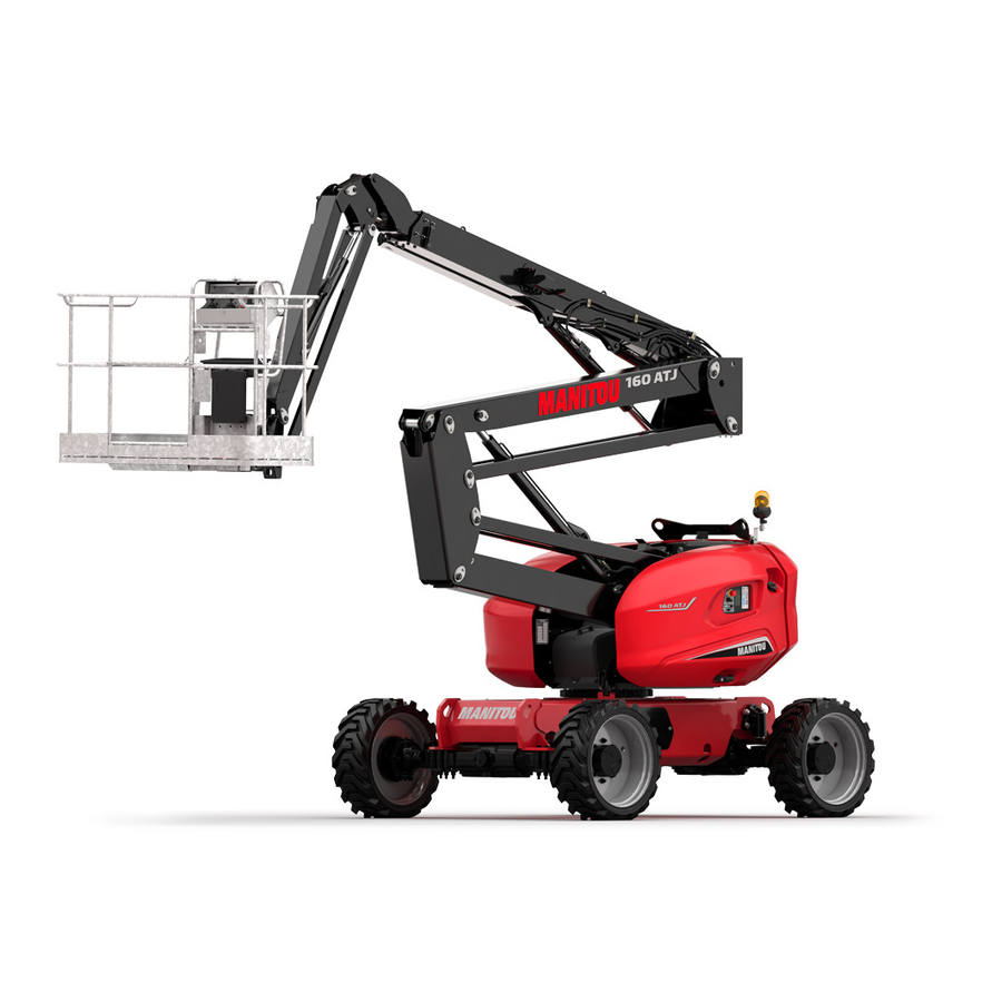
160 ATJ PLUS Euro 3
180 ATJ Euro 3
180 ATJS Euro 3
INSTRUCTIONS MANUAL
THIS INSTRUCTIONS MANUAL MUST BE KEPT PERMANENTLY IN THE LIFT TRUCK AND THE OPERATORS MUST HAVE READ AND FULLY UNDERSTOOD IT.
Advertisement
Chapters
Table of Contents

Related Manuals for Manitou 160 ATJ PLUS Euro 3

Summary of Contents for Manitou 160 ATJ PLUS Euro 3
- Page 1 44158 ANCENIS CEDEX - FRANCE TEL: + 33 (0)2 40 09 10 11 YOUR DEALER 547408 EN (15/05/2012) 160 ATJ PLUS Euro 3 180 ATJ Euro 3 180 ATJS Euro 3 INSTRUCTIONS MANUAL THIS INSTRUCTIONS MANUAL MUST BE KEPT PERMANENTLY IN THE LIFT TRUCK AND THE OPERATORS MUST HAVE READ AND FULLY UNDERSTOOD IT.
- Page 2 The platform has been designed and produced to enable you to perform your overhead work completely safely. Before it was delivered, MANITOU and the dealer have carefully inspected the platform so that it comes to you in perfect working order.
- Page 3 1 - INSTRUCTIONS AND SAFETY ADVICE 2 - DESCRIPTIONS 3 - MAINTENANCE 4 - ELECTRICITY 07/12/2010 Publication date 21/11/2011 Update (1-20 ; 1-23 ; 2-10 ; 2-12 ; 2-15 ; 2-18 ; 2-19 ; 2-22 ; 2-23 ; 2-26 ; 2-28 ; 2-34 ; 2-35 ; 2-40 ; 2-41 ;...
- Page 4 160 ATJ PLUS Euro 3 FRONT REAR 180 ATJ Euro 3 FRONT REAR...
- Page 5 1 - OPERATING 1 - OPERATING AND SAFETY AND SAFETY INSTRUCTIONS INSTRUCTIONS...
-
Page 7: Table Of Contents
TABLE OF CONTENTS NSTRUCTIONS TO THE COMPANY MANAGER REAMBLE HE OPERATOR HE PLATFORM HE INSTRUCTIONS HE MAINTENANCE NSTRUCTIONS FOR THE OPERATOR REAMBLE ENERAL NSTRUCTIONS RIVING NSTRUCTIONS 1-15 NSTRUCTIONS FOR WELDING AND BLOW TORCH WORK ON THE EXTERNAL STRUCTURE 1-16 LATFORM MAINTENANCE INSTRUCTIONS 1-16 ENERAL INSTRUCTIONS 1-16... -
Page 8: Instructions To The Company Manager
S SUITABILITY FOR US - MANITOU has ensured that this platform is suitable for use under the standard operating conditions defined in this operator’s manual, with an overload test coefficient of 1,25 and an operational test coefficient of 1,1, as stipulated in standardised norm EN 280 for MPLP (Mobile Personnel Lifting Platforms). -
Page 9: The Instructions
For operation under average climatic conditions, i.e. : between -15 °C and + 35 °C, correct levels of lubricants in all the circuits are checked in production. For operation under more severe climatic conditions, before starting up, it is necessary to drain all the circuits, then ensure correct levels of lubricants using lubricants properly suited to the relevant ambient temperatures. -
Page 10: Instructions For The Operator
INSTRUCTIONS FOR THE OPERATOR REAMBLE WHENEVER YOU SEE THIS SYMBOL IT MEANS : WARNING ! BE CAREFUL ! YOUR SAFETY OR THE SAFETY OF THE PLATFORM IS AT RISK. The risk of accident while using, servicing or repairing your platform can be restricted if you follow the safety instructions and safety measures detailed in these instruction. - Page 11 C - M AINTENANCE - The operator must immediately advise his superior if his platform is not in good working order or does not comply with the safety notice. - The operator is prohibited from carrying out any repairs or adjustments himself, unless he has been trained for this purpose. He must keep the platform properly cleaned if this is among his responsibilities.
-
Page 12: Driving Instructions
- Safety helmets must be worn. - MANITOU recommends a safety harness in the operator’s size be provided when the platform is in use (for the harness attachement in the basket , see chapter 2 - DESCRIPTION, CHECKING AND CONTROL INSTRUMENTS pages). - Page 13 - Do not allow anybody to come near the working area of the platform or pass beneath an elevated load. To do this, mark your operating area with warning signs. - Travelling on a longitudinal slope : - Take into account the platform’s dimensions and its load before trying to negotiate a narrow or low passageway. - Never move onto a loading platform without having first checked : - Never move onto a foot bridge, floor or freight lift, without being certain that they are prescribed for the weight and size of the platform to be loaded and without having checked that they are in sound working order.
- Page 14 If the wind is in excess of 45Km/h, do not perform any movements liable to endanger the lifting platform’s stability. - To recognise this speed by eye, please refer to the empirical wind evaluation scale below: BEAUFORT scale (wind speed at a height of 10m over flat terrain) Speed Speed Speed...
- Page 15 D - V ISIBILITY - Maintain permanently good visibility throughout the route. To increase your visibility, you can move forwards with the pendular arm slightly raised (pay attention to the risk of falls in the basket from knocking into a low doorway, overhead electric wires, travelling cranes, highway bridges, tracks or any obstacle in the area in front of the platform).
- Page 16 E - S TARTING THE PLATFORM PLATFORMS WITH IC ENGINES SAFETY NOTICE - Do not pull or push the lifting platform to start it. This type of manoeuvre would cause severe damage to the transmission. In cases of necessity, towing requires that the lifting platform be placed in freewheeling mode (See chapter 3 - MAINTENANCE). - If using an emergency battery for start-up, use a battery with the same characteristics and respect battery polarity when connecting it.
- Page 17 F - D RIVING THE PLATFORM SAFETY NOTICE Operators should be aware of the risks connected with using the platform, notably: - Risk of losing control. - Risk of losing lateral and frontal stability of the platform. The operator must remain in control of the platform. - Do not carry out operations which exceed the capacities of your platform.
- Page 18 G - S TOPPING THE PLATFORM SAFETY NOTICE - Never leave the ignition key in the platform during the operator’s absence. - Make sure that the platform is not stopped in any position that will interfere with the traffic flow and at less than one meter from the track of a railway.
-
Page 19: Instructions For Welding And Blow Torch Work On The External Structure
NSTRUCTIONS FOR WELDING AND BLOW TORCH WORK ON THE EXTERNAL STRUCTURE Ensure that there are no hydraulic or electrolyte leaks on the platform. When welding, work in the opposite direction from the control console to avoid sparks damaging it . - Any welding and cutting (blow torch) work from the basket on a building’s metallic structures requires the following precautions to be taken: A - W... -
Page 20: Platform Maintenance Instructions
PLATFORM MAINTENANCE INSTRUCTIONS ENERAL INSTRUCTIONS - Ensure the area is sufficiently ventilated before starting the platform. - Wear clothes suitable for the maintenance of the platform, avoid wearing jewellery and loose clothes. Tie and protect your hair, if necessary. - Stop the I.C. engine before conducting any work on the platform, remove the ignition key and disconnect the “Minus” battery terminal. -
Page 21: Hydraulic
YDRAULIC - Make any repairs and fix any leaks, including minor ones, immediately. - Do not attempt to loosen unions, hoses or any hydraulic component with the circuit under pressure. BALANCING VALVE : It is dangerous to change the setting and remove the balancing valves or safety valves which may be fitted to your platform cylinders. -
Page 22: If The Platform Is Not To Be Used For A Long Time
The following recommendations are intended to prevent the platform from being damaged when it is withdrawn from service for an extended period. For these operations, we recommend the use of a MANITOU protective product, reference 603726. Instructions for using the product are given on the packaging. -
Page 23: Charging The Batteries
HARGING THE BATTERIES - In the case of electric platforms, in order to preserve the batteries’life and their capacity, check them periodically and keep the charge level constant (see : 3 - MAINTENANCE). ROTECTING THE PLATFORM Protect cylinder rods which will not be retracted, from corrosion. - Wrap the tyres. - Page 24 SAFETY LABELS 160ATJ Plus 160 ATJ PLUS EURO 3 598892 A 400 N (40 Kg - 90 Lbs) 230 Kg = 70 Kg + 510 Lbs = 155 Lbs + 598897 12.5 m/s (45km/h) 5° 676814 160ATJ & 180ATJ 180 ATJ EURO 3...
- Page 25 1 - W 1-22 HITE ARROW 2 - B 1-22 LACK ARROW 3 - B 1-22 ASKET INSTRUCTIONS LOAD CAPACITY 1-23 AFETY INSTRUCTIONS 1-23 OWING 1-23 ASHING RECOMMENDATIONS 5 - W 1-23 HEEL LOAD 6 - L 1-24 OCATION OF THE PLATFORM KEY 7 - M 1-24 ANUAL CONTROL PROCEDURE...
-
Page 26: White Arrow
EANINGS 1 - W HITE ARROW This indicates the translation direction when moving forward. When the turret assembly, arm structure and the basket are rotating 180° with respect to the chassis, the translation controls are reversed. Identify the forward motion direction by looking at the arrows on the chassis and those on the basket control console. -
Page 27: Towing
AFETY ADVICE Read and take note of the operating instructions and safety measures before starting the lifting platform. OWING This sticker indicates that the machine should not be towed if it breaks down. ASHING RECOMMENDATIONS It is strictly forbidden to use a pressure washer to clean the control knobs and the electrical components. -
Page 28: Ocation Of The Platform Key
6 - L OCATION OF THE PLATFORM KEY The duplicate platform keys (ignition, control selection, cover-opening keys...) are stored in this location specially provided. 7 - M ANUAL CONTROL PROCEDURE This describes the procedure for performing movements with the emergency pump and the manual controls when an accident or breakdown occurs that makes the electrical control box inoperative. -
Page 29: Isk Of Being Crushed
9. R ISK OF BEING CRUSHED It is strictly forbidden to insert your fingers, or any other part of your body, in the lifting structure’s components (arms, scissors, pendular arm, etc.); there is a risk of being crushed. 10 - D ANGER KEEP AWAY It is strictly forbidden to walk under or park under the structure (arms, scissors, jib-... -
Page 30: Risk Of Burns
13 - R ISK OF BURNS This sticker indicates that there is a significant risk of your being burnt in this region (engine silencer, IC engine, etc.). 683112 14 - A RM SUPPORT This sticker informs you of the use of a maintenance support when working on the lifting platform in operating position. -
Page 31: Ie Down Hook
17 - T DOWN HOOK This sticker shows the location of the anchoring points for tying the platform on a lorry bed. (see 3 – OCCASIONAL MAINTENANCE). 18 - H YDRAULIC OIL This indicates that this reservoir is designed only to hold hydraulic oil. NB: see MAINTENANCE: LUBRICANTS 597652 19 - D... - Page 32 1-28...
- Page 33 2 - DESCRIPTION 2 - DESCRIPTION...
- Page 35 » D CLARATION CONFORMIT - 180 ATJ S E 2-10 IFTING PLATFORM 160 ATJ PLUS EURO 3 - 180 ATJ EURO 3 - 180 ATJ S EURO 3 2-12 HARACTERISTICS 160 ATJ PLUS EURO 3 2-13 HARACTERISTICS 180 ATJ EURO 3 - 180 ATJ S EURO 3...
-
Page 36: Ec" Declaration Of Conformity - 160 Atj Plus Euro
«EC» DECLARATION OF CONFORMITY - 160 ATJ PLUS EURO 3 DÉCLARATION «CE» DE CONFORMITÉ (originale) « EC» DECLARATION OF CONFORMITY (original) La société, : MANITOU BF The company Adresse, Address 430, rue de l’Aubinière - BP 10249 - 44158 - ANCENIS CEDEX - FRANCE... - Page 37 bg : 1) cs : 1) da : 1) de : 1) el : 1) es : 1) et : 1) fi : 1) ga : 1) hu : 1) is : 1) it : 1) lt : 1) lv : 1) mt : 1) nl : 1) no : 1)
-
Page 38: Ec" Declaration Of Conformity - 180 Atj Euro
430, rue de l’Aubinière - BP 10249 - 44158 - ANCENIS CEDEX - FRANCE Dossier technique, Technical file MANITOU BF - 430, rue de l’Aubinière BP 10249 - 44158 - ANCENIS CEDEX - FRANCE Constructeur de la machine décrite ci-après,... - Page 39 bg : 1) cs : 1) da : 1) de : 1) el : 1) es : 1) et : 1) fi : 1) ga : 1) hu : 1) is : 1) it : 1) lt : 1) lv : 1) mt : 1) nl : 1) no : 1)
-
Page 40: Ec" Declaration Of Conformity - 180 Atj S Euro
430, rue de l’Aubinière - BP 10249 - 44158 - ANCENIS CEDEX - FRANCE Dossier technique, Technical file MANITOU BF - 430, rue de l’Aubinière BP 10249 - 44158 - ANCENIS CEDEX - FRANCE Constructeur de la machine décrite ci-après,... - Page 41 bg : 1) cs : 1) da : 1) de : 1) el : 1) es : 1) et : 1) fi : 1) ga : 1) hu : 1) is : 1) it : 1) lt : 1) lv : 1) mt : 1) nl : 1) no : 1)
-
Page 42: Lifting Platform Id
LIFTING PLATFORM ID ’ ’ IFTING PLATFORM S MANUFACTURER S PLATE ’ OCATION OF THE MANUFACTURER S PLATE C ENGINE 2-10... - Page 43 YDROSTATIC PUMP RONT AXLE EAR AXLE 2-11...
-
Page 44: Characteristics 160 Atj Plus Euro 3 - 180 Atj Euro 3 - 180 Atj S Euro 3
CHARACTERISTICS 160 ATJ PLUS EURO 3 - 180 ATJ EURO 3 - 180 ATJ S EURO 3 NGINE 4 in line - Bore - Mass OOLING CIRCUIT - Fan - Starts to open at 82°C LECTRICAL CIRCUIT - Earth Negative... -
Page 45: Characteristics 160 Atj Plus Euro 3
CHARACTERISTICS 160 ATJ PLUS EURO 3 YDROSTATIC TRANSMISSION Hydrostatic pump - Reverser 300 bar - Filtration UXILIARY HYDRAULIC CIRCUIT 210 Bar ONNECTION BOX FUSES - F1 7,5 A - F2 20 A - F3 20 A - F4 20 A... -
Page 46: Characteristics 180 Atj Euro 3 - 180 Atj S Euro 3
CHARACTERISTICS 180 ATJ EURO 3 - 180 ATJ S EURO 3 YDROSTATIC TRANSMISSION Hydrostatic pump - Reverser 300 bar - Filtration UXILIARY HYDRAULIC CIRCUIT 210 Bar ONNECTION BOX FUSES - F1 7,5 A - F2 20 A - F3 20 A - F4 20 A - F5... -
Page 47: Specifications 160 Atj Plus Euro 3
SPECIFICATIONS 160 ATJ PLUS EURO 3 PÉCIFICATIONS Indoors and outdoors 4 wheel drive - 4 wheel steer - Rotation tourelle : 160 AJT Plus Standard Continue - Operating speed - Transport speed Slow speed Gradient speed - Operating height - Floor height - Traversable slope &... -
Page 48: Specifications 180 Atj Euro 3
SPECIFICATIONS 180 ATJ EURO 3 PÉCIFICATIONS Indoors and outdoors 4 wheel drive - 4 wheel steer - Rotation tourelle : 180 AJT Standard Continue - Operating speed - Transport speed Slow speed Gradient speed - Operating height - Floor height - Traversable slope OUES AVANT ARRIERE... -
Page 49: Specifications 180 Atj S Euro 3
SPECIFICATIONS 180 ATJ S EURO 3 PÉCIFICATIONS Indoors and outdoors 4 wheel drive - 2 wheel steer - Rotation tourelle : - Operating speed - Transport speed Slow speed Gradient speed - Operating height - Floor height - Traversable slope OUES AVANT ARRIERE - Pressure... -
Page 50: Atj Plus Euro
DIMENSIONS 160 ATJ PLUS EURO 3 2200 2370 2705 2300 1325 3680 4040 6322 2742 3160 4050 8450 7574 14200 7150 2-18... -
Page 52: Dimensions 180 Atj Euro 3
DIMENSIONS 180 ATJ EURO 3 7775 5770 2200 2370 2560 2300 1325 3665 4530 6875 2730 3660 4580 10040 15635 14250 7150 2-20... - Page 53 2-21...
-
Page 54: Dimensions 180 Atj S Euro 3
DIMENSIONS 180 ATJ S EURO 3 7780 5770 2200 2370 2560 2300 2500 5360 6830 3600 47° ou 107% 15165 3505 13780 4420 7155 2-22... - Page 55 2-23...
-
Page 56: Lifting Platform Operation
LIFTING PLATFORM OPERATION ESCRIPTION - The base console is fitted with a so called “Dead man’s” button 2*. This must be held down at the same time as switching over a contactor. Releasing it stops the movement. ENERAL 2-24 2-24... - Page 57 AFETY TILT situation: OVERLOAD the overload, 2-25 2-25...
-
Page 58: Base Control Instrumentation
BASE CONTROL INSTRUMENTATION A - G ROUND MAINTENANCE AND EMERGENCY STATION 2-26 2-26... - Page 59 A - G ROUND MAINTENANCE AND EMERGENCY STATION 1 - KEY-OPERATED IGNITION SWITCH 2 - STARTER BUTTON 3 - GROUND OR PLATFORM CONTROL SELECTRO SWITCH 4 - EMERGENCY STOP 5 - LOW-TEMPERATURE ENGINE START-UP AID 6 - INTERFACE SCREEN 7 - INFORMATION VALIDATION SCREEN KEYS 8 - DEAD MAN’S BUTTON 9 - BASKET TILT DOWN / TILT UP BUTTON 10 - TURRET ROTATION KEYS...
-
Page 60: Basket Control Instrumentation
BASKET CONTROL INSTRUMENTATION B - B ASKET CONTROL STATION 2-28 2-28... - Page 61 B - B ASKET CONTROL STATION 20 - UPPER ARM UP / DOWN AND TURRET ROTATION CONTROL LEVER 21 – LOWER ARMS UP / DOWN AND TELESCOPE EXTENSION / RETRACTION CONTROL LEVER 22 – LIFTING PLATFORM FORWARD / REVERSE AND RIGHT / LEFT MOVEMENT CONTROL JOYSTICK 23 - EMERGENCY STOP 24 - “PREHEATING”...
- Page 62 GROUND MAINTENANCE AND EMERGENCY STATION 1 - K OPERATED IGNITION SWITCH Position 2 Position 1 POSITION 1 POSITION 2 2 - S TARTER BUTTON BUTTON 2 3 - G ROUND OR PLATFORM CONTROL SELECTION SWITCH Position 1 Position 2 POSITION 1 POSITION 2 2-30...
- Page 63 4 - E MERGENCY STOP 5 - L TEMPERATURE ENGINE START UP AID Position 2 1 : SUN POSITION Position 1 2 : SNOW POSITION 2-31...
- Page 64 6 - I NTERFACE SCREEN 7 - I NFORMATION VALIDATION SCREEN KEYS FUNCTIONS OF THE KEYBOARD KEYS: 7A : 7B : 7C : 7D : 7E : 7F : 2-32...
- Page 65 8 - D ’ EAD MAN S BUTTON Position 2 9 - B ASKET TILT DOWN TILT UP BUTTON 9A : TILTING THE BASKET DOWNWARDS 9B : TILTING THE BASKET UPWARDS 10 - T URRET ROTATION KEYS 10A : ROTATING THE TURRET LEFT 10B : ROTATING THE TURRET RIGHT 2-33...
- Page 66 11 - L OWER ARM LIFTING AND LOWERING KEYS A : LIFTING THE LOWER ARMS B: LOWERING THE LOWER ARMS 12 - U PPER ARM LIFTING AND LOWERING KEYS A : LIFTING THE UPPER ARM B: LOWERING THE UPPER ARM 13 - T ELESCOPE EXTENSION AND RETRACTION KEYS A : RETRACTING THE TELESCOPE...
- Page 67 15 - B LOCKING TURRET ROTATION 16 - F LASHING LIGHT 17 - T ILT SENSOR 18 - B UZZER 2-35...
- Page 68 19 - B ASE EMERGENCY PUMP BUTTON 2-36...
- Page 69 2-37...
-
Page 70: Basket Control Station
BASKET CONTROL STATION 20 - U PPER ARM UP DOWN AND TURRET ROTATION CONTROL LEVER RAISING THE UPPER ARM LOWERING THE UPPER ARM ROTATING RIGHT ROTATING LEFT 21 - L OWER ARMS UP DOWN AND TELESCOPE EXTENSION RETRACTION CONTROL LEVER RAISING THE LOWER ARMS LOWERING THE LOWER ARMS EXTENDING THE TELESCOPE... - Page 71 22 - L IFTING PLATFORM FORWARD REVERSE AND RIGHT LEFT MOVEMENT CONTROL JOYSTICK FORWARD TRANSLATION REAR TRANSLATION STEER RIGHT STEER LEFT 23 - E MERGENCY STOP...
- Page 72 24 - “P ” I REHEATING NDICATOR LIGHT 25 - S TART UP CONTROL BUTTON 26 - “E ” NGINE FAULT LIGHT 2-40...
- Page 73 27 - 28 S TEERING MODE SELECTOR AND AXLE REALIGNMENTS POSITION 1 POSITION 2 POSITION 3 28A FRONT WHEEL ALIGNMENT 28B REAR WHEEL ALIGNMENT 2-41...
- Page 74 29 - B UZZER CONTROL BUTTON 30 - D IFFERENTIAL LOCKING CONTROL BUTTON - To use this, press button 30 and release the button to interrupt its use and note a 31 - L OW FUEL LEVEL INDICATOR 2-42...
- Page 75 32 - T RANSLATION SPEED SELECTION CONTACTOR POSITION 1 : POSITION 2 : POSITION 3 : position 3 4-wheel drive position 2 33 - “O ” I VERLOAD NDICATOR LIGHT 34 - “T ” I NDICATOR LIGHT 35 - “U ”...
- Page 76 37 - B ASKET ROTATION CONTACTOR RIGHT ROTATION LEFT ROTATION 38 - B ASKET PENDULAR ARM CONTACTOR RAISING THE PENDULAR ARM LOWERING THE PENDULAR ARM 39 - B “ ” B ASKET EMERGENCY PUMP UTTON 40 - “D ’ ” P EAD MAN EDAL 2-44...
- Page 77 41 - B UZZER UNDER THE BASKET CONSOLE 42 - S AFETY HARNESS HOOK UP POINTS 43 - L ISSE DE SÉCURITÉ 2-45...
- Page 78 1B - SCREEN DISPLAY DIAGRAM 45 46 49 50 SCREEN PARAMETERS: top) bottom) MAINTENANCE VALID PAGE BY 17 18 20 21 TO BE DISPLAYED: ENTERING THE SECRET CODE page: 13 14 MENU - Cipher selection: - / + (bottom) - Confirmation of the cipher, switch-over to the next cipher and confirmation of the complete code...
- Page 79 NB: In the sub-menus, pressing the MENU key brings you back to the main Menu page and pressing the ESC key brings you back to the preceding sub-menu. See Repairs Manual 547371 ENGINE Level 2 and 3 - Confirm the selection NB: If there is an engine fault (major fault, the fault icon is shown highlighted.
-
Page 80: Screen Display - Description Of The Pages
SCREEN DISPLAY - DESCRIPTION OF THE PAGES 2 - PRESENTATION PAGE PRESENTATION PAGE : 3 - PRE-HEATING PAGES PRE-HEATING PAGES : CONTROL / CAN TRANSFER PAGE : START-UP PAGE : 2-48... - Page 81 5 - WORK PAGES PAGE FOR WORKING FROM THE BASE (NO FAULTS SHOWING) PAGE FOR WORKING FROM THE BASKET (NO FAULTS SHOWING) 1: Slow speed 2: Moderate speed NB: The speed when operating from the base is always Speed 2. Only the engine operating hours counter is visible when no fault or maintenance symbol is present in the system.
- Page 82 6 - FAULT PAGES THE MAJOR FAULTS POSSIBLE ARE AS FOLLOWS: CAN BUS FAULT PAGE LOW POWER SUPPLY FAULT PAGE LOW DIESEL LEVEL FAULT PAGE NB: Program W678600-002, screen page deleted. ENGINE WATER TEMPERATURE FAULT PAGE ENGINE OIL PRESSURE FAULT PAGE BATTERY CHARGE FAULT PAGE ARM POSITION SENSOR (WORK SPEED / TRANSPORT SPEED) FAULT PAGE...
- Page 83 LTHE MINOR FAULTS POSSIBLE ARE AS FOLLOWS: TURRET ROTATION JOYSTICK FAULT PAGE OVERLOAD FAULT PAGE TILT FAULT PAGE FORWARD MOTION JOYSTICK FAULT PAGE LOWER ARMS JOYSTICK FAULT PAGE UPPER ARM JOYSTICK FAULT PAGE TELESCOPE JOYSTICK FAULT PAGE 2-51...
- Page 84 THE MAINTENANCE FAULTS POSSIBLE ARE AS FOLLOWS: OIL CHANGE MAINTENANCE FAULT PAGE OIL FILTER MAINTENANCE FAULT PAGE AIR FILTER MAINTENANCE FAULT PAGE DIESEL FILTER MAINTENANCE FAULT PAGE HYDRAULIC FILTER MAINTENANCE FAULT PAGE HYDROSTATIC FILTER MAINTENANCE FAULT PAGE GREASING MAINTENANCE FAULT PAGE MECHANICAL INSPECTION MAINTENANCE FAULT PAGE 2-52...
- Page 85 ACCESS CODE PAGE ACCESS CODE PAGE : for entry of the secret code, see diagram MENU PAGE SETTINGS PAGES The parameters on pages 25 and can be reinitialised to the default parameters. See pages MAINTENANCE PAGES the statuses) If there are maintenance operations to be performed (confirmed after start-up), Maintenance pages appear before the view of the counters.
-
Page 86: Using The Lifting Platform
USING THE LIFTING PLATFORM TRANSPORT POSITION FORWARD TRANSLATION Cran 2 REVERSE TRANSLATION EFORE STARTING THE LIFTING PLATFORM TARTING THE LIFTING PLATFORM 2-54... - Page 87 OVEMENT IN RANSPORT ORK MODE - Transport mode: TRANSPORT MODE - Work mode : NB: You must use Ramp speed (full power with the speed restricted to 2 km/h) to cross over steep slopes or move over very broken ground. This can prove very useful, for instance, if an access ramp must be borrowed to move the lifting platform onto a truck bed.
- Page 88 NSTALLATION ON THE WORK SITE AND LIFTING NB: When the lifting platform is free of the chassis, translation switches automatically to slow speed. Only the pendular arm can be raised completely while maintaining Transport speed. Familiarise yourself with the instruments on the ground maintenance and emergency station and in the basket, described in the previous pages and in particular the warnings specifying the risks involved in performing certain...
- Page 89 2-57...
- Page 90 OADING UNLOADING THE LIFTING PLATFORM Transport position: OADING ROCEDURE FOR FOLDING THE LIFTING PLATFORM 160 ATJ PLUS : 2-58...
- Page 91 ASHING DOWN THE LIFTING PLATFORM...
-
Page 92: Rescue Procedure
RESCUE PROCEDURE F THE OPERATOR FALLS ILL N THE EVENT OF AN ACCIDENT OR BREAKDOWN LECTRICAL BREAKDOWN - To raise and lower the lower arms 2-60... - Page 93 To extend and retract the telescope To raise and lower the upper arm Rescue procedure on the main distributor: To rotate the turret left To rotate the turret right To raise the pendular arm To lower the pendular arm 2-61...
- Page 94 EPAIRING REAKDOWN ASKET CONTROL STATION 2-62...
- Page 95 PROPORTIONAL DISTRIBUTOR Lowering the Raising the Extending the Lowering the Raising the Rotating the turret Raising/lowering the 2-63...
- Page 96 Raising the MAIN DISTRIBUTOR Rotating the Lowering the Rotating the turret right 2-64...
-
Page 97: Accessories
ACCESSORIES ENERATOR PTION 2-65... - Page 98 2 - 20” WHEEL OPTION + WIDE BASKET OPTION ON 180 ATJ SPECIFICATIONS - Operating height - Floor heigh FRONT - REAR TYRES LOAD PER TYRE EMPTY FLOOR AREA TYRES DIMENSIONS FILLING FOAM 430 - CM2 2-66...
- Page 99 180 ATJ 7800 2413 2300 2-67...
- Page 100 2-68...
- Page 101 3 - MAINTENANCE 3 - MAINTENANCE...
- Page 103 CONTENTS MANITOU REPLACEMENT PARTS AND ORIGINAL EQUIPMENT COMMISSIONING CHECK LIST FILTER ELEMENTS AND BELTS LUBRICANTS AND FUEL 3 / 180 3-10 AINTENANCE TABLE ATJ PLUS EURO ATJ EURO 3-12 DAILY OR EVERY HOURS OF OPERATION 3-14 EVERY HOURS OF OPERATION...
-
Page 104: Manitou Replacement Parts And Original Equipment
- Improvements based on feedback from experience. - Training of the operating personnel. - Only the Manitou network knows the lifting platform’s design in detail and therefore has the best technical capabilities to provide for its maintenance. ORIGINAL REPLACEMENT PARTS ARE ONLY DISTRIBUTED BY MANITOU AND ITS DEALER NETWORK. -
Page 105: Commissioning Check List
COMMISSIONING CHECK LIST 0 = Good 1 = Missing 2 = Incorrect IC ENGINE ACCESSORIES 01 Air filter 01 Adaptations to the machine 02 Fuel tank 02 Hydraulic connections 03 Fuel lines - Filter CAB / PROTECTOR / ELECTRICAL CIRCUIT 04 Injection or carburettor system 01 Seat 05 Radiator and cooling system... -
Page 106: Filter Elements And Belts
FILTER ELEMENTS AND BELTS IC ENGINE IC ENGINE OIL FILTER FAN BELT Reference: 749613 Reference: 749605 Replace: 500 H Replace: 500 H DRY AIR FILTER CARTRIDGE Reference: 227959 Clean: 50 H Replace: 500 H DRY AIR FILTER SAFETY CARTRIDGE Reference: 227960 Replace: 1000 H* FUEL FILTER CARTRIDGE Reference: 781909... -
Page 108: Lubricants And Fuel
USE THE RECOMMENDED LUBRICANTS AND FUEL: - Oils may not be mixed when topping up. - MANITOU oils are perfectly suitable for easy draining. OIL DIAGNOSTIC ANALYSIS If you set up a maintenance or servicing contract with the dealer, a diagnostic analysis of the engine and axle oils may be requested, depending on the usage level. - Page 109 GEAR BEARING RACEWAYS LUBRICATION SHELL MALLEUS GL 205 TURRET CROWN GEAR TEETH LUBRICATION Aerosol 744802 499237 MANITOU SAE80W90 25 l 546330 BRAKE REDUCER ON THE TURRET’S REDUCTION GEAR axle / gearbox mechanical 56 l 546221 transmission oil 215 l 546220...
-
Page 110: Maintenance Table
MAINTENANCE TABLE (1): COMPULSORY OVERHAUL AFTER 500 HOURS or 6 MONTHS This overhaul must compulsorily be performed after approximately the first 500 hours of operation or 6 months after the machine is put into service (when the earlier of the two periods is reached). (2): The engine oil and the engine oil filter must be replaced after the first 50 hours of operation, and then every 500 hours of operation. - Page 111 A = REGULATE, C = CHECK, G = GREASE, N = CLEAN, PAGE P = BLEED, R = REPLACE, V = DRAIN ELECTRICITY Condition of the joystick bellows 3-13 <<< <<< <<< <<< <<< <<< Level of electrolyte in the battery 3-14 <<<...
- Page 112 A - DAILY OR EVERY 10 HOURS OF OPERATION A1 - IC ENGINE OIL LEVEL CHECK Set the lifting platform on a horizontal surface with the engine switched off and let the oil drain back into the sump. - Open the left-hand cover - Remove the dipstick 1 (Fig.
- Page 113 A4/1 A4 - BRAKING CHECK Check that the cotter pins 1 (Fig. A4/1) and 2 (Fig. A4/2) are in place on the rear axle. If these pins are not in place, the machine has not brakes. A4/2 A5 - HYDRAULIC OIL LEVEL CHECK Set the lifting platform on a horizontal surface in Transport position with the engine switched off.
- Page 114 B - EVERY 50 HOURS OF OPERATION Perform the operations described above as well as the following operations. B1/1 B1 - LEVEL OF BATTERY ELECTROLYTE CHECK Check the electrolyte level in each battery. If the ambient temperature is high, check the level more often than every 50 hours of operation.
- Page 115 B3 - AXLES B3/1 B3/2 GREASE - Grease nipples for the pivots on the front and rear wheel reducers 1 (Fig. B3/1) and 2 (Fig. B3/2) (8 grease nipples) - Grease nipples for the front axle oscillation B3/3 B3/4 shaft 3 (Fig. B3/3) and 4 (Fig. B3/4)(2 grease nipples).
- Page 116 B5 - ALTERNATOR/CRANKSHAFT/FAN BELT TENSION B5/1 ADJUST - Open the left-hand cowl. - Check the condition of the belt for any signs of wear or cracking and replace it, if necessary (see: 3 - MAINTENANCE: FILTER ELEMENTS AND BELTS). - Check the tension between the crankcase and alternator pulleys. - Under thumb pressure (98 N), the tension A (Fig.
- Page 117 B7 - DRY AIR FILTER CARTRIDGE B7/1 CLEAN If you are using the machine in a very dusty atmosphere, reduce these maintenance intervals; see the FILTER ELEMENTS AND BELTS section. - Open the left-hand cowl. - Unclip the cover 1 (Fig. B7/1). - Release the filter cartridge 2 (Fig.
-
Page 118: C - Every 250 Hours Of Operation
C - EVERY 250 HOURS OF OPERATION C1 - FRONT & REAR AXLE DIFFERENTIAL OIL LEVEL C1/1 CHECK Set the lifting platform on a horizontal surface, with the engine switched off. DIFFERENTIAL: - Remove the plug 1 (Fig. C1/1); the oil level should be flush with the hole. - If necessary, top up the oil through the same hole (see the LUBRICANTS section). - Page 119 C3 - FRONT AND REAR WHEEL REDUCER OIL LEVEL CHECK Set the lifting platform on a horizontal surface, with the engine switched off. - Check the level in each of the front wheel reducers. - Set the level plug 1 (Fig. C3) horizontal. - Remove the level plug;...
- Page 120 C7 - TURRET REDUCTION GEAR BRAKE REDUCER LEVEL CHECK Set the lifting platform on a horizontal surface, with the engine switched off. - Remove the turret’s internal cowl. - The reduction gear is revealed with the valve block to the rear. - Remove the sniffler-filling plug 1 (Fig.
- Page 121 C9 - AXLES GREASE - Clean and then grease the following points (see the LUBRICANTS section for details of the grease) and remove the surplus. Legend : AXLE JOINT 3-21...
- Page 122 C10 - TIGHTNESS OF THE BOLTS FIXING THE AXLE ASSEMBLIES ON THE CHASSIS CHECK - The tightness of the bolts must be checked at the latest after the first 50 hours of operation, and every 250 hours of operation thereafter. - The tightening torque for the bolts is 28.5 daN.m ±...
- Page 123 C15 - FUEL FILTER C15/1 CLEAN - Set the lifting platform on a horizontal surface, with the engine switched off. - Open the left-hand cowl. - Close the fuel tap 1 (Fig. C15/1) to the OFF position. - Carefully clean the exterior of the filter and its holder to prevent dust from entering the system.
-
Page 124: D - Every 500 Hours Of Operation
D - EVERY 500 HOURS OF OPERATION D1 - DRY AIR FILTER CARTRIDGE D1/1 REPLACE The air used for combustion is purified by a dry air filter. It is therefore forbidden to use the lifting platform with the cartridge removed or damaged. - Open the left-hand cowl. - Page 125 D3 - HYDROSTATIC TRANSMISSION OIL FILTER CARTRIDGE REPLACE REPLACING THE HYDROSTATIC TRANSMISSION OIL FILTER CARTRIDGE - Switch off the engine. - Lift the cowl on the engine side. - Unscrew the filter body 1 (Fig. D3). - Remove the hydrostatic transmission oil filter cartridge and replace it with a new one.
- Page 126 D5 - HYDRAULIC OIL D5/1 DRAIN - REPLACE - Set the lifting platform on a horizontal surface in Transport position with the engine switched off. DRAINING THE OIL - Lay a receptacle under the drain plug 1 (Fig. D5/1) and loosen the collar 2 (Fig. D5/1).
- Page 127 D8 - TURRET MOTOR REDUCER BRAKE REDUCER DRAIN - REPLACE Set the lifting platform on a horizontal surface with the engine switched off. - Remove the turret’s inner cover. - The motor reducer is presented with the valve unit to the rear. - Remove the sniffler/filling cap 2 (Fig.
- Page 128 D10 - DENSITY OF THE BATTERY ELECTROLYTE CHECK 1.240 1.250 The electrolyte’s density varies according to the temperature but a minimum level 1.260 of 1260 at 16°C must be maintained. 1.270 In the hatched section (Fig. D10), the battery is normally charged. 1.280 Above the hatched section, the battery must be recharged.
- Page 129 D14 - IC ENGINE OIL D15/1 DRAIN - REPLACE D15 - IC ENGINE OIL FILTER REPLACE - Set the lifting platform on a horizontal surface, leave the engine running at tickover speed for a few moments and then switch it off. DRAINING THE OIL - Open the left-hand cover.
-
Page 130: E - Every 1000 Hours Of Operation
E - EVERY 1000 HOURS OF OPERATION E1 - FUEL TANK E1/1 DRAIN - CLEAN Never smoke or approach the machine with a naked flame during this operation. Set the lifting platform on a horizontal surface, rotate the machine 90° (so as to avoid having the drain plug over the chassis) and switch off the engine. - Page 131 E3 - FRONT AND REAR AXLE DIFFERENTIAL OIL E3/1 DRAIN - REPLACE Set the lifting platform on a horizontal surface with the engine switched off and the differential oil still warm. - Lay a receptacle under the drain plugs 1 (Fig. E3/1: front axle) (Fig. E3/2: rear axle).
- Page 132 E5 - HYDRAULIC CIRCUIT STRAINER E5/1 CLEAN - Drain the oil (see § D15) - Unscrew the six fixing screws 1 (Fig. E5/1) from the locking plate 2 (Fig. E5/1). - Unscrew the strainer 3 (Fig. E5/2) from the container and clean it with a jet of compressed air.
-
Page 133: F - Every 2000 Hours Of Operation
F - EVERY 2000 HOURS OF OPERATION Perform the operations described above as well as the following operations. F1/1 F1 - COOLANT DRAIN - REPLACE This series of operations must only be performed as necessary or once a year, on the approach of winter. - Page 134 Perform the operations described above as well as the following operations. F2 - VALVE PLAY (*) CHECK - ADJUST F3 - WATER PUMP AND THERMOSTAT (*) CHECK F4 - ALTERNATOR AND STARTER (*) CHECK F5 - HYDRAULIC OIL RESERVOIR (*) CLEAN F6 - HYDRAULIC CIRCUIT PRESSURES (*) CHECK...
- Page 135 G - OCCASIONAL MAINTENANCE G1 - FUEL FEED CIRCUIT G1/1 BLEED This series of operations must only be performed under the following circumstances: - A component in the supply circuit replaced or drained. - Ensure that there is sufficient fuel in the tank; turn the ignition key to notch 2 to make electrical contact.
- Page 136 G2 - WHEEL G2/1 CHANGE Or this operation, we recommend that you use the MANITOU hydraulic jack, reference 505507, and the MANITOU safety stand, reference 554772. - Stop the lifting platform, if possible, on a firm, horizontal surface. - Proceed to stop the lifting platform (see: 1 – SAFETY INSTRUCTIONS AND ADVICE: INSTRUCTIONS FOR DRIVING WHEN UNLADEN AND LADEN).
- Page 137 G3 - LIFTING PLATFORM HOISTING WITH A SLING For lifting platform 180 ATJ, see Fig. G3/1 For lifting platform 160 ATJ Plus, see Fig. G3/2 - Note the position of the lifting platform’s centre of gravity for lifting it. - Place hooks on the anchoring points A provided for this purpose. - Strap the end of the front axle carriers with flexible straps.
- Page 138 G3/1 180 ATJ Euro3 180 ATJS Euro3 CENTRE OF GRAVITY LOAD ON THE WHEELS IN TRANSPORT POSITION TOTAL WEIGHT OF LIFTING PLATFORM: -180 ATJ EURO 3: 8090 Kg - 180 ATJS EURO 3: 7820 Kg 3-38...
- Page 139 G3/2 160 ATJ PLUS Euro 3 CENTRE OF GRAVITY 1100 LOAD ON THE WHEELS IN TRANSPORT POSITION 160 ATJ PLUS : 1940 Kg 160 ATJ PLUS : 2110 Kg 160 ATJ PLUS : 2110 Kg 160 ATJ PLUS : 1940 Kg...
- Page 140 G4 - LIFTING PLATFORM ON A TRUCK BED TRANSPORT - See Section 2: LOADING / UNLOADING THE LIFTING PLATFORM. G5 - FREEWHEELING (160 ATJ PLUS EURO 3) G5/1 ACTIVE In the event that the lifting platform must be towed, follow the instructions below.
- Page 141 G6 - REEWHEELING (180 ATJ EURO 3 / 180 ATJS EURO 3) ACTIVE In the event that the lifting platform must be towed, follow the instructions below. The lifting platform may only be towed a short distance and necessarily by a vehicle with significant braking power in order to be able to hold it and with a tow bar fitted between the two vehicles.
- Page 142 G6 - MAINTENANCE STAND G6/1 If you have to make repairs to the arms, the turret, the engine, etc. Follow the instructions below: - From the base console, order the lower arms to rise until the upper joint is 1m above the counterweight (Fig.
- Page 143 4 - ELECTRICITY 4 - ELECTRICITY...
- Page 145 FUSES ESCRIPTION OF THE FUSES AND THEIR REPLACEMENT The fuses are located in the connection box (Fig. A1) fixed to the turret inside the base control box. Switched off To access the fuses, open the cabinet door 1 (Fig. A2) and remove the hatch 2 (Fig.
Need help?
Do you have a question about the 160 ATJ PLUS Euro 3 and is the answer not in the manual?
Questions and answers