Table of Contents
Advertisement
Quick Links
44158 ANCENIS CEDEX - FRANCE
THIS OPERATOR'S MANUAL MUST BE KEPT IN THE STACKER AND MUST BE READ AND UNDERSTOOD BY OPERATORS.
MANITOU BF
BP 10249
TEL: 33 (0)2 40 09 10 11
YOUR DEALER
647263 EN (06/12/2012)
STACKY
STACKY 10 FR S16 - STACKY 10 FR D28
STACKY 10 LE S16 - STACKY 10 LE D28
STACKY 14
OPERATOR'S MANUAL
(ORIGINAL MANUAL)
Advertisement
Chapters
Table of Contents

Related Manuals for Manitou STACKY 10 FR S16


Summary of Contents for Manitou STACKY 10 FR S16
- Page 1 44158 ANCENIS CEDEX - FRANCE TEL: 33 (0)2 40 09 10 11 YOUR DEALER 647263 EN (06/12/2012) STACKY STACKY 10 FR S16 - STACKY 10 FR D28 STACKY 10 LE S16 - STACKY 10 LE D28 STACKY 14 OPERATOR'S MANUAL (ORIGINAL MANUAL)
- Page 2 STACKY 14 STACKY 10 LE S16 STACKY 10 FR D28...
- Page 3 1 - OPERATING AND SAFETY INSTRUCTIONS 2 - DESCRIPTION 3 - MAINTENANCE 4 - TOOLS 06/12/2012 edition THE TEXT AND ILLUSTRATIONS IN THIS DOCUMENT MUST NOT BE REPRODUCED EITHER WHOLLY OR IN PART.
- Page 5 OPERATING AND SAFETY INSTRUCTIONS...
- Page 6 STACKY operating and safety instructions 2012.12...
-
Page 7: Table Of Contents
TABLE OF CONTENTS INSTRUCTIONS TO THE COMPANY MANAGER THE SITE ............1-5 THE OPERATOR . - Page 8 MEANING OF THIS SYMBOL: WARNING! BE CAREFUL ! YOUR SAFETY OR THAT OF OTHERS IS AT RISK RISK OF DAMAGE TO THE STACKER STACKY operating and safety instructions 2012.12...
-
Page 9: Instructions To The Company Manager
A - FITNESS OF THE STACKER FOR PURPOSE MANITOU has ensured that this stacker is suitable for use under the standard operating conditions defined in this operator's manual, with a STATIC test coefficient of 1,33 and a DYNAMIC test coefficient of 1, as specified in standard EN 1726-1 for industrial trucks . - Page 10 STACKY operating and safety instructions 2012.12...
-
Page 11: Instructions For The Operator
INSTRUCTIONS FOR THE OPERATOR PREAMBLE All the stackers and tools described in these instructions are standard stackers and standard tools respectively . The tools are only interchangeable in the case of standard tools and standard stackers . The risk of accident while using, servicing or repairing your stacker can be reduced if you follow the safety instructions and safety measures detailed in this operator’s manual. -
Page 12: Unladen And Laden Stacker Operating Instructions
UNLADEN AND LADEN STACKER OPERATING INSTRUCTIONS A - PRIOR TO USING THE STACKER Prior to using the stacker, the operator must check that there is no one within the danger zone (1 .5 times the maximum stacker lift height) and keep unauthorised persons outside this zone . It is, in particular, forbidden to stay close to moving parts . If, in spite of a warning, people refuse to leave the danger zone, the operator must not continue using the stacker . -
Page 13: D - Visibility
Do not allow anybody to approach the working area of the stacker or to pass beneath the load (fig . C1) . Take into account the stacker’s dimensions and its load before trying to negotiate a narrow or low passageway . Never move onto a loading platform without having first checked : - that it is suitably positioned and made fast, - that the unit to which it is connected (wagon, lorry, etc .) will not shift,... - Page 14 - Move the stacker smoothly at an appropriate speed for the operating conditions (ground profile, load on the stacker), - Do not use the lifting or lowering controls when the lift truck is moving, - Approach bends, narrow passages or swing doors, as well as any sector where visibility is reduced, at reduced speed, - Make sure you are in control of your speed under all circumstances, - Brake gently, never abruptly,...
-
Page 15: G - Stopping The Stacker
G - STOPPING THE STACKER SAFETY INSTRUCTIONS - When the stacker is stationary, or if the operator has to the leave the operator’s position (even for a moment), place the forks or tool in the down position . INSTRUCTIONS - Park the stacker on level ground, - Place the fork or tool in the down position (fig . -
Page 16: Instructions For Handling A Load
INSTRUCTIONS FOR HANDLING A LOAD A - CHOICE OF TOOL (EXCEPT STACKY 14) Only tools approved or authorised by the manufacturer are to be used on its stackers . Check that the tool is appropriate for the task to be performed . Certain specific applications require non-standard stackers to be used . -
Page 17: D - Picking Up And Setting Down A Load
D - PICKING UP AND SETTING DOWN A LOAD Lifting and lowering are controlled by means of two buttons situated on the tiller arm (1) and (2) (fig . D1) . These controls are duplicated to be equally accessible for left or right hand use . -
Page 18: F - Picking Up A Load In A Storage Structure
F - PICKING UP A LOAD IN A STORAGE STRUCTURE - As you approach the storage structure, slow the stacker to arrive at moderate speed, - Position the stacker in front of its storage location, - Check that no obstacle risks to be caught by the fork or the tool as it is raised, - Raise the fork so that the underside is slightly higher than the bearing surface (1) (fig . F1), - Operate a butterfly control switch to move slowly forward and insert the fork under... -
Page 19: H - Travelling With A Suspended Load (Except Stacky 14)
H - TRAVELLING WITH A SUSPENDED LOAD (EXCEPT STACKY 14) - Carry the load in the down position (max . 150 mm from the ground) with the shortest possible boom length (fig .H1), - Secure the load (1) (fig . H1), mini - Take all precautions when moving high loads, - The stacker must not travel at more than 0,4 m/s (1,5 km/h, i .e ., one quarter walking... -
Page 20: Stacker Maintenance Instructions
STACKER MAINTENANCE INSTRUCTIONS GENERAL INSTRUCTIONS Wear clothes suitable for the maintenance of the stacker, avoid wearing jewellery and loose clothes . Read the operator's manual carefully . Carry out all necessary repairs at the earliest possible opportunity, even if the repairs concerned are minor . Repair all leaks at the earliest possible opportunity, even if the leak concerned is minor . -
Page 21: Stacker Decommissioning And Disposal
STACKER DECOMMISSIONING AND DISPOSAL DECOMMISSIONING The operator must remove the stacker from service under the following conditions : • Immediately an anomaly is detected in the operation of the machine, • The moment the condition of the machine no longer allows safe working (cracks or deformations in the fork arms, wheels in poor condition, tool in poor condition, etc .), • Safety devices are missing or not working, • The regulatory markings on the machine are no longer legible,... - Page 23 DESCRIPTION...
- Page 24 Description - STACKY 2012.12...
- Page 25 TABLE OF CONTENTS EC DECLARATION OF CONFORMITY SAFETY PLATES AND STICKERS EXTERNAL PLATES AND STICKERS ........2-6 STACKER IDENTIFICATION STACKER MANUFACTURER'S PLATE (fig.
- Page 26 Adresse, 430, rue de l’Aubinière - BP 10249 - 44158 - ANCENIS CEDEX - FRANCE Address Dossier technique, MANITOU BF - 430, rue de l’Aubinière Technical file BP 10249 - 44158 Ancenis CEDEX FRANCE Constructeur de la machine décrite ci-après,...
- Page 27 bg : 1) удостоверение за « СЕ » съответствие (oригинална), 2) Фирмата, 3) Адрес, 4) Техническо досие, 5) Фабрикант на описаната по-долу машина, 6) Обявява, че тази машина, 7) Отговаря на следните директиви и на тяхното съответствие национално право, 8) За машините към допълнение IV, 9)Номер на удостоверението, 10) Наименувана фирма, 15) хармонизирани...
- Page 28 PART NUMBER DESCRIPTION 24653 Lifting point logo J509960 STACKY label Stacker manufacturer’s plate J509819 Safety label 240807 MANITOU label J510076 STACKY 10ac label J510075 STACKY 14ac label 234804 Open book logo Tool manufacturer’s plate J509959 Battery charge level label Description - STACKY...
- Page 29 STACKER IDENTIFICATION As our policy is to promote a constant improvement of our products, our range of stackers may undergo certain modifications, without obligation for us to advise our customers . MODELE When ordering spare parts or requesting technical information, always specify the CAP.
- Page 30 TECHNICAL CHARACTERISTICS CODIFICATION Manufacturer MANITOU Type SK 10 FR S16 SK 10 FR D28 SK 10 LE S16 SK 10 LE D28 SK 14 CHARACTERISTICS Mode of propulsion Battery Type of operation Pedestrian Rated load capacity 1000 1000 1400 Centre of gravity of load...
- Page 31 DIMENSIONS STACKY 10 FR STACKY 10 LE h1/h4 STACKY 14 2012.12 Description - STACKY...
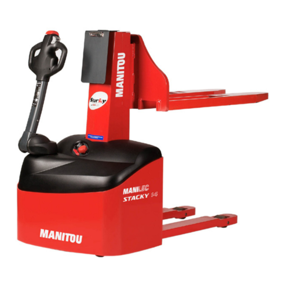
- Page 32 TECHNICAL DESCRIPTION VOLTS 17 - Lifting chain 1 - Moving frame 18 - Charging lead 2 - Slinging point 19 - Down button 3 - Chassis 20 - Up button 4 - Tiller arm 21 - Tortoise button 5 - Cover fastening screw 22 - Horn button 6 - Dashboard 23 - Butterfly control switch...
- Page 33 The tool mounted on the stacker must be the appropriate tool for the task to be performed . Only tools approved by MANITOU can be used on the stacker . The tools are attached to the carriage by means of a hook and two M10 screws . Some tools are provided with a lifting ring for ease of handling (jib, narrow-aisle fork) .
- Page 34 13 - CHARGE INDICATOR This shows the level of charge of the batteries, indicated by five green LEDs, two yellow LEDs and three red LEDs . Alternately flashing red LEDs indicate that the minimum charge has been reached . 14 - EMERGENCY STOP BUTTON This device stops stacker movements in emergency situations .
- Page 35 30 - FUSES The stacker's electrical equipment is protected by three fuses . They are located close to the electronic speed controller . 31 - HORN 32 - BATTERIES The stacker is powered by means of two 12 V batteries connected in series . These are of the drive battery type, with a capacity of 85 Ah (5 hours rate) .
- Page 37 MAINTENANCE...
- Page 38 Maintenance - STACKY 2012.12...
- Page 39 TABLE OF CONTENTS ORIGINAL MANITOU SPARE PARTS AND EQUIPMENT START-UP CHECKLIST LUBRICANTS SERVICING SCHEDULE A - DAILY CHECKS A1 - BRAKING EFFICIENCY ......... . 3-9 A2 - WHEEL AND ROLLER WEAR .
- Page 40 Maintenance - STACKY 2012.12...
-
Page 41: Original Manitou Spare Parts And Equipment
- Efficient help with diagnosis, - Improvements due to experience feedback, - Operator training, - Only the MANITOU network has detailed knowledge of the design of the stacker and therefore the best technical ability to provide maintenance . ORIGINAL REPLACEMENT PARTS ARE DISTRIBUTED EXCLUSIVELY BY MANITOU AND ITS DEALER NETWORK. -
Page 42: Start-Up Checklist
START-UP CHECKLIST 0 = OK 1 = Missing 2 = Incorrect HYDRAULIC CIRCUIT 01 Tank 02 Pumps and couplings 03 Tightening of connections 04 Lift cylinder(s) BRAKING SYSTEM 01 Service brake and parking brake operation LUBRICATION AND GREASING MAST ASSEMBLY 01 Fixed and mobile frame 02 Carriage 03 Chain (remove protection) -
Page 43: Lubricants
LUBRICANTS USE THE RECOMMENDED OILS : As not all oils are miscible, top up with MANITOU oils only. MAST ORGANS TO BE LUBRICATED RECOMMENDATION PACKAGING PART NUMBER 400 g 545996 MANITOU Grease GREASING OF THE MAST 1 kg 161590 BLACK multi-purpose... -
Page 44: Servicing Schedule
SERVICING SCHEDULE C = CHECK, G = GREASE, N = CLEAN, PAGE R = REPLACE, V = DRAIN WHEELS Braking efficiency 3-11 Wheel nuts torque Wheel and roller wear MAST Mast 3-13/3-14 3-14 Carriage Chain tension SUPPORT LEGS 3-11 Clearance adjustment HYDRAULIC Hydraulic system operation 3-11... -
Page 45: A - Daily Checks
A - DAILY CHECKS A1 - BRAKING EFFICIENCY CHECK When the tiller arm is in zones (1) and (3) (fig . A1), the electromagnetic brake must lock the drive wheel . A2 - WHEEL AND ROLLER WEAR CHECK The drive unit, the stabilising wheel and the rear rollers must show no signs of cutting or wear . A3 - CHAIN TENSION CHECK After having placed the forks or the tool in the down position, the chain must be tight . -
Page 46: A8 - Condition And Attachment Of Fork Or Tool (Except Stacky 14)
A8 - CONDITION AND ATTACHMENT OF FORK OR TOOL (except STACKY 14) CHECK The fork or tool must not show any visible signs of damage, such as: deformation, cracking or heavy wear . The fork or tool must be securely attached to avoid any risk of accident . Check the tightening of the two screws holding the fork or the tool on the carriage . -
Page 47: B - Monthly
B - MONTHLY Carry out the operations described previously as well as the following operations : B1 - TIGHTENING OF WHEEL NUTS CHECK Check the tightening of the nuts and screws : - of the drive wheel with a tightening torque of 125 Nm (±15%) (1) (fig . B1/1), - of the stabiliser wheel spindle with a tightening torque of 70 Nm (±20%) (2) (fig . -
Page 48: B5 - Fuses
B5 - FUSES CHECK Check the condition and rating of the three fuses . These are located close to the speed controller : - speed controller fuse (1) (fig . B5) : 30 A (STACKY 10) or 50 A (STACKY 14), - power circuit fuse (2) (fig . -
Page 49: C - Every Six Months
C - EVERY SIX MONTHS Carry out the operations described previously as well as the following operations : C1 - MAST GREASE Clean and lubricate the following points with grease (see : 3 - MAINTENANCE : LUBRICANTS) and remove surplus grease . SK 10 FR S16, SK 10 LE S16, SK 14 : - the mast guide rails (1) (fig . -
Page 50: D - Yearly
D - YEARLY Carry out the operations described previously as well as the following operations : D1 - MAST CHECK SK 10 FR D28 and SK 10 LE D28 D1/1 Check the clearance between the moving frame and the chassis . If necessary, adjust : - the nylon slide pad (1) (fig . -
Page 51: E - Occasional
E - OCCASIONAL E1 - BATTERY FAILURE CHANGE Handling and servicing a battery can be dangerous, take the following precautions : • wear protective goggles and clothing, • hold the battery horizontally when handling, • never smoke or work near a naked flame, • work in a well-ventilated area, • in the event of electrolyte being spilled onto the skin or splashed in the eyes, rinse thoroughly with cold water for 15 minutes and call a doctor. - Page 52 - check that the capacity of the tail lift is compatible with the weight of the machine to be loaded, - when raising or lowering the tail lift, the stacker’s parking brakes must be applied to prevent any risk of falling . The fork or the tool must remain in the down position .
- Page 53 TOOLS...
- Page 54 Tools - STACKY 2012.12...
- Page 55 TABLE OF CONTENTS INTRODUCTION TECHNICAL CHARACTERISTICS TOOLS FOR THE STACKY 10 STACKER ........4-7 2012.12 Tools - STACKY...
- Page 56 Tools - STACKY 2012.12...
- Page 57 Certain special applications require the use of non-standard tools that are specific to their stacker and are not interchangeable . Only tools approved by MANITOU are to be used on our stackers. The manufacturer shall not be liable for any modifications or adaptations made to its tools without its written approval.
- Page 58 TECHNICAL CHARACTERISTICS m i n Ø 70 Tools - STACKY 2012.12...
- Page 59 TOOLS FOR THE STACKY 10 STACKER Tool part Centre of B1 min B1 max Weight gravity of number load Unit 1000 1025 1000 1150 1185 POT * 1000 Ø 60 1000 1000 1057 * LE model only 2012.12 Tools - STACKY...
Need help?
Do you have a question about the STACKY 10 FR S16 and is the answer not in the manual?
Questions and answers