Table of Contents
Troubleshooting

Related Manuals for Canon CR-G100


Summary of Contents for Canon CR-G100
- Page 1 PUB. DIE-0546-000 CR-G100 IP Camera Controller Instruction Before using the product, carefully read this Instruction Manual and be sure to Manual use the product correctly. Retain the Instruction Manual for future reference.
-
Page 2: Table Of Contents
Overview ·············································································································································································· 8 Conventions Used in this Document ················································································································ 8 Names of Parts ·································································································································································· 9 CR-G100 IP Camera Controller ··························································································································· 9 Standalone Base Adapter ···································································································································· 9 3 System Connections ················································································································ 10 Mounting the IP Controller ······································································································································· 10 Connecting the Cables ················································································································································... - Page 3 Troubleshooting ····························································································································································· 29 List of Messages ·················································································································································· 30 Resetting the IP Controller to Factory Settings ····························································································· 30 Specifications ·································································································································································· 31 CR-G100 IP Camera Controller ·························································································································· 31 6 Appendix·································································································································· 32 Connection/Installation Checklist ··························································································································· 32 Detailed Dimensions ···················································································································································· 33 ...
-
Page 4: Important Safety And Handling Instructions
Contact If foreign objects (metallic objects, liquids, a Canon sales representative as soon as possible. etc.) get inside the product. WARNING Denotes the risk of serious injury or death. Transportation/Installation ... -
Page 5: Handling Precautions
1 Important Safety and Handling Instructions Handling Precautions Handling Do not use organic solvents such as alcohol, Do not get the product wet. Do not insert foreign benzene or paint thinner to clean the product. objects or liquids into the product. ... -
Page 6: Disclaimers
For further information on repairs, maintenance, or adjustments not mentioned in this instruction manual, contact a Canon sales representative. Note that Canon may be unable to undertake servicing or repair of a product if it is modified without consulting Canon or your Canon sales representative. -
Page 7: Introduction
2 Introduction Components 2 Introduction Components These are the components supplied in the package when the CR-G100 is bought separately. Before using this product, make sure the package contains all the items listed below. CR-G100 N3 Cable Standalone Base Adapter... -
Page 8: Overview
Overview Thank you for purchasing this Canon IP camera controller. This instruction manual covers the operation of the CR-G100 IP Camera Controller and how to use the web setup tool to set up a robotic camera system. For the latest information about this product, please visit your local Canon website. -
Page 9: Names Of Parts
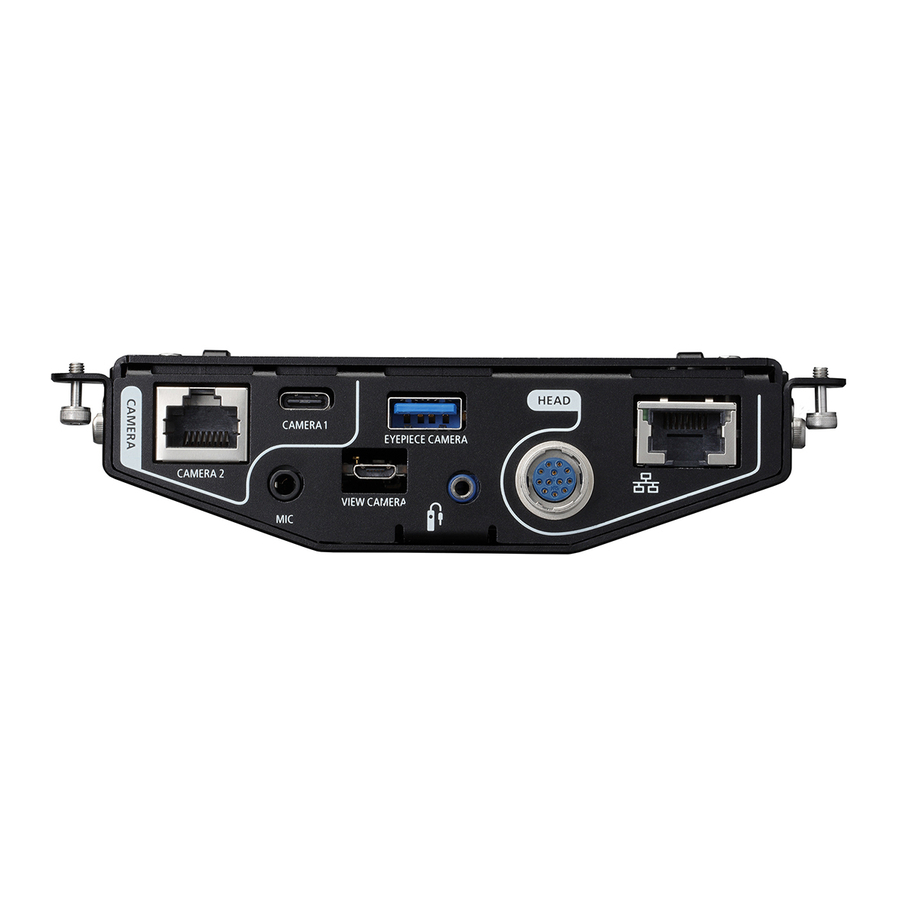
2 Introduction Names of Parts Names of Parts CR-G100 IP Camera Controller CAMERA2 terminal* CAMERA1 terminal* EYEPIECE CAMERA terminal* HEAD terminal* (Ethernet) terminal* Hex head bolts (M6, x4) MIC (microphone) terminal VIEW CAMERA terminal* (N3 Remote) terminal* Ethernet 1000 Mbps link indicator (A 11) -
Page 10: System Connections
3 System Connections Mounting the IP Controller 3 System Connections Mounting the IP Controller If you are not using a CR-S700R Robotic Camera Head, turn the IP controller upside-down and attach the standalone base adapter to the IP controller’s top surface (now at the bottom). Use the screw holes at the bottom of the standalone base adapter (3 each for 1/4"... - Page 11 (1) USB Type C cable Main capture camera (sold separately) PoE hub Control PC (7) LAN cable FTP server CR-G100 IP Camera Controller (8) AC adapter (3) N3 cable (supplied) (4) USB cable (5) USB cable Wide view camera Eyepiece camera...
-
Page 12: Attaching The Ferrite Core To The Lan Cable
3 System Connections Connecting the Cables Attaching the Ferrite Core to the LAN Cable Attach the supplied ferrite core to the end of the LAN cable (commercially available) used to connect to the PoE hub. This will reduce noise interferences. Place the ferrite core about 3 cm (1.2 in.) from the LAN cable’s connector. -
Page 13: Turning The System On/ Off
3 System Connections Turning the System On/ Off Turning the System On/ Off When not using a camera head, use the following procedures to turn the system on and off. Turning the system on When the IP controller’s power is off, slide the power switch once in the direction of the arrow to turn on the system. The green power/status indicator will illuminate and the orange indicator will flash slowly (once per second). -
Page 14: Configuration
11. Turn off the camera head or IP controller (A 13). Starting Up the Web Setup Tool For details about the web setup tool’s system requirements (compatible OS, web browsers, etc.), visit your local Canon website. Disable automatic proxy settings. -
Page 15: Changing The Ip Controller's Ip Address
4 Configuration Starting Up the Web Setup Tool Launch the web browser on the control PC and access the following URL. http://<IP address> At initial settings, the IP controller’s IP address is set to [192.168.0.1]. Only the first time Enter the same password twice and click [Set]. -
Page 16: The Web Setup Tool Screen
4 Configuration The Web Setup Tool Screen The Web Setup Tool Screen [Register] tab: Settings for registering connected devices [Operation] tab: Main operation panel [Status] tab: Status information Robotic Camera Head Settings menu button Menu button Display/Setup area... -
Page 17: Registering Connected Devices
4 Configuration Registering Connected Devices Registering Connected Devices Click the [Register] tab to display the [Register Devices] screen. In this screen you can check the connection status of the main capture camera, lens, camera head, wide view camera and eyepiece camera, and register them as part of the system. Except for the robotic camera head’s model name, the information displayed is obtained automatically from the connected devices. -
Page 18: Elements Of The Main Operation Panel
4 Configuration Elements of the Main Operation Panel Elements of the Main Operation Panel Click the [Operation] tab to display the following screen. Range of motion control area Shooting parameters area Live view display area Number of remaining available shots Rotate button ... -
Page 19: Selecting The Lens Used
4 Configuration Selecting the Lens Used Selecting the Lens Used After the initial installation and after replacing the lens, click [ ] (Robotic Camera Head Settings menu) > [Control] > [Devices] > [Lens] and select the lens model attached to the main capture camera. When using a lens model not included in the list, select [Unspecified] instead. -
Page 20: Setting The Motion Speed
4 Configuration Setting the Camera Head’s Motion Range Setting the Motion Speed Set the operation speed for pan, tilt, roll and zoom motion to one of three levels: [High], [Medium] or [Low]. The actual speeds assigned to each speed level can be changed using the Robotic Camera Head Settings menu (A 26). ... -
Page 21: Setting The Zoom Motion Range
4 Configuration Setting the Camera Head’s Motion Range Setting the Zoom Motion Range Click [ ] or [ ] to zoom out and zoom in, respectively. Click [ ] to zoom in until the lens’s wide-angle end and then click [Wide-angle Limit] to confirm the motion limit. Current zoom Current zoom motion range... -
Page 22: Using Camera Head Preset Positions
4 Configuration Using Camera Head Preset Positions Using Camera Head Preset Positions You can register a set of pan, tilt, roll and zoom positions as a preset position in advance and easily move the camera head to the preset position later on. Preset position list Move to preset position Register as preset position... -
Page 23: Changing The Main Capture Camera's Shooting Settings
4 Configuration Checking the Operation of the Main Capture Camera Changing the Main Capture Camera’s Shooting Settings Depending on the main capture camera used, you will be able to change some shooting settings such as AF mode, shooting mode, shutter speed, aperture value and exposure compensation. Available values will vary depending on the camera used. -
Page 24: Checking The System With The Status Screen
4 Configuration Checking the System with the Status Screen Checking the System with the Status Screen Click the [Status] tab to display an overview of relevant information about the system. In the information screen you can check the connected devices registered and their connection status as well as the motion range limits on all axes. You can also set the IP controller to READY status or clear this status. -
Page 25: Updating The Ip Controller's Firmware Version
Updating the IP Controller’s Firmware Version Updating the IP Controller’s Firmware Version Obtain the firmware update file and save it on the control PC. Firmware update files are available for download from the local Canon website. Click [ ] (menu) > [Update firmware]. -
Page 26: Menu Settings And Operations
4 Configuration Menu Settings and Operations Menu Settings and Operations Robotic Camera Head Settings Menu While the operation panel ([Operation] tab) is displayed, click [ ] to open the Robotic Camera Head Settings menu. With the menu settings under the [Operation] and [Control] tabs, you can change the operation of the camera head and connected devices. - Page 27 4 Configuration Menu Settings and Operations Menu item Setting options and additional information [Max speed for preset] Select the maximum pan/tilt/roll speed used when moving the camera head to a preset position. To change the setting, remove the checkmark from the [Default] box. [Pan (30 –...
-
Page 28: Menu
4 Configuration Menu Settings and Operations Menu Click [ ] to open a menu where you can log out from the IP controller, change system settings and perform various maintenance operations. Menu item Setting options and additional information [Log out] Log out from the IP controller. -
Page 29: Additional Information
5 Additional Information Troubleshooting 5 Additional Information Troubleshooting The IP controller does not start up. When using the system with a camera head: Connect the camera head to the IP controller’s HEAD terminal. When using the system without a camera head: The (Ethernet) terminal may not be connected to the PoE hub ... -
Page 30: List Of Messages
5 Additional Information Troubleshooting Images are not transferred to the FTP server. A card was not inserted into the main capture camera or the card is full. Replace the card with one with sufficient available space. Check the FTP server settings. For details, refer to the chapter about wired (Ethernet) networks in the instruction ... -
Page 31: Specifications
5 Additional Information Specifications Specifications CR-G100 IP Camera Controller Temperature: -15 °C to 40 °C Operation environment Humidity: 90% RH or lower (without condensation) Fixtures Attachment using M3 hex head bolts, x4 HEAD terminal For connection to the camera head CAMERA1 terminal USB 3.0 (SuperSpeed), Type C connector... -
Page 32: Appendix
6 Appendix Connection/Installation Checklist 6 Appendix Connection/Installation Checklist Use the following checklist to verify correct operation after connecting/installing the IP controller. This checklist is applicable only when using the IP controller without a CR-S700R Robotic Camera Head. When using a camera head, refer to the checklist in the CR-S700R instruction manual. -
Page 33: Detailed Dimensions
6 Appendix Detailed Dimensions Detailed Dimensions CR-G100 IP Camera Controller 38.2 141.6 34.4 132.6 (attachment pitch) 31.4... -
Page 34: Standalone Base Adapter
6 Appendix Detailed Dimensions Standalone Base Adapter 4x M3 through-hole, for attachment to the IP Camera Controller 141.6 70.8 3x 1/4" 3x 3/8" 132.6... -
Page 35: Index
7 Index (Ethernet) terminal ..........9, 11, 31 Login ....................14 (N3 Remote) terminal ........... 9, 11, 31 Main capture camera ............10, 22 Autofocus ..................23 Menu settings..............26, 28 Message list ................. 30 Cable connections ..............10 Mounting ..................10 Camera head ................ - Page 36 7 7BIndex Testing the operation of the VIEW CAMERA terminal ..........9, 11, 31 main capture camera ............. 22 Tilt ....................20 Troubleshooting ................ 29 Web setup tool ................14 Turning the IP controller on/off .......... 13 Wide view camera ..............7, 10 Underslung mode ..............
- Page 37 Canon Inc. 30-2, Shimomaruko 3-chome, Ohta-ku, Tokyo 146-8501, Japan The information in this document is verified as of January 2020. Subject to change without notice. © CANON INC. 2020...
Need help?
Do you have a question about the CR-G100 and is the answer not in the manual?
Questions and answers