Rockwell Automation Allen-Bradley PowerFlex 755T Installation Instructions Manual
Hide thumbs
Also See for Allen-Bradley PowerFlex 755T:
- Programming manual (130 pages) ,
- Installation instructions manual (22 pages) ,
- Reference manual (128 pages)

Related Manuals for Rockwell Automation Allen-Bradley PowerFlex 755T


Summary of Contents for Rockwell Automation Allen-Bradley PowerFlex 755T
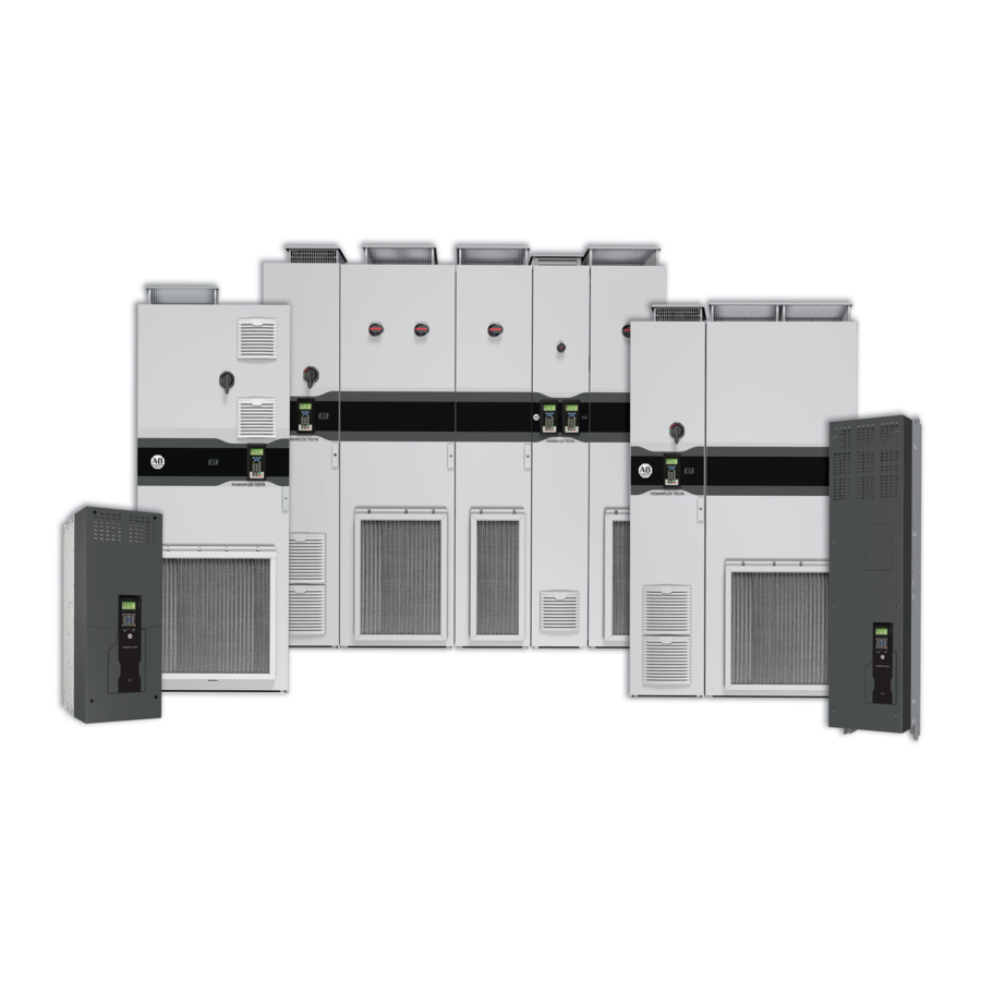
- Page 1 PowerFlex 755T Drives Configured to Order Program Catalog Numbers 24G, 24J Installation Instructions Original Instructions...
- Page 2 If this equipment is used in a manner not specified by the manufacturer, the protection provided by the equipment may be impaired. In no event will Rockwell Automation, Inc. be responsible or liable for indirect or consequential damages resulting from the use or application of this equipment.
-
Page 3: Table Of Contents
Remove Side and Top Packaging ....... . . 45 Installation Remove Detached Installation Hardware......46 Rockwell Automation Publication 750-IN118A-EN-P - May 2021... - Page 4 RFI Filter Grounding......... 95 Rockwell Automation Publication 750-IN118A-EN-P - May 2021...
- Page 5 Task Code Explanations ........127 Recommended Maintenance Tasks and Schedule ....128 Rockwell Automation Publication 750-IN118A-EN-P - May 2021...
- Page 6 Notes: Rockwell Automation Publication 750-IN118A-EN-P - May 2021...
-
Page 7: Preface
Download Firmware, AOP, Access the Product Compatibility and Download Center at rok.auto/pcdc EDS, and Other Files download firmware and associated files (such as AOP, EDS, and DTM), and access product release notes. Rockwell Automation Publication 750-IN118A-EN-P - May 2021... -
Page 8: Additional Resources
Provides guidance on how to conduct security assessments, implement Rockwell System Security Design Guidelines Reference Manual, SECURE-RM001 Automation products in a secure system, harden the control system, manage user access, and dispose of equipment. Rockwell Automation Publication 750-IN118A-EN-P - May 2021... - Page 9 Industrial Automation Wiring and Grounding Guidelines, publication 1770-4.1 Provides general guidelines for installing a Rockwell Automation industrial system. To view or download publications, go to rok.auto/literature. To access declarations of conformity, certificates, and other certification details, go to rok.auto/certifications.
- Page 10 Notes: Rockwell Automation Publication 750-IN118A-EN-P - May 2021...
-
Page 11: Product Overview
ATTENTION: Only qualified personnel familiar with adjustable frequency AC drives and associated machinery should plan or implement the installation, startup, and subsequent maintenance of the system. Failure to comply can result in personal injury and/or equipment damage. Rockwell Automation Publication 750-IN118A-EN-P - May 2021... -
Page 12: Personal Safety
Drives Configured to Order Program products of size frame 8 and higher during operation. Follow applicable local, national, and international codes, standards, regulations, or industry guidelines for hearing protection when exposed to potentially damaging noise hazards. Rockwell Automation Publication 750-IN118A-EN-P - May 2021... -
Page 13: Product Safety
ATTENTION: Configuring an analog input for 0…20 mA operation and driving it from a voltage source could cause component damage. Verify proper configuration before applying input signals. Product Certifications and Rockwell Automation maintains current product certification information on Specifications its website at rok.auto/certifications. -
Page 14: Data Nameplate
Product Rating Cross-references topic in 750-IN100. Figure 2 - Configured Input Bay Interior Data Figure 1 - Example Configured Input Bay Data Nameplate Nameplate on Top Touch Guard Nameplate Rockwell Automation Publication 750-IN118A-EN-P - May 2021... -
Page 15: Catalog Number Explanation
35 are a three-letter code for the language of the publications that are shipped with the product. Because of the variability in the number of codes and characters after position 35, these positions are not numbered. Rockwell Automation Publication 750-IN118A-EN-P - May 2021... -
Page 16: Product Type And Voltage Rating
8…9 IP54, UL Type 12; Floor Mount 8…9 Voltage Rating Code Voltage Frames 400V AC; 3 PH 8…9 480V AC; 3 PH 8…9 600V AC; 3 PH 8…9 690V AC; 3 PH 8…9 Rockwell Automation Publication 750-IN118A-EN-P - May 2021... -
Page 17: Product Normal Duty Rating
1040 1112 1045 1175 1135 1000 1463 1365 1100 PowerFlex 755T ND Drive Ratings PowerFlex 755T ND Drive Ratings 600V, 60 Hz Input 690V, 50 Hz Input Code Amps Frame Code Amps Frame Rockwell Automation Publication 750-IN118A-EN-P - May 2021... - Page 18 1193 1075 1261 1167 1570 1404 PowerFlex 755TM ND Bus Supply Ratings PowerFlex 755TM ND Bus Supply Ratings 600V, 60 Hz Input 690V, 50 Hz Input Code Amps Frame Code Amps Frame 1008 Rockwell Automation Publication 750-IN118A-EN-P - May 2021...
- Page 19 1365 1100 PowerFlex 755T Normal Duty Common Bus Inverter Ratings PowerFlex 755T Normal Duty Common Bus Inverter Ratings 600V, 60 Hz Input 690V, 50 Hz Input Code Amps Frame Code Amps Frame 1000 Rockwell Automation Publication 750-IN118A-EN-P - May 2021...
-
Page 20: Additional Drive Configuration
(1) Not available on Frames 8…9. Door-mounted Human Interface Module (HIM) Code Operator Interface and Control Frames No HIM with TotalFORCE Control 8…9 Enhanced LCD, Full Numeric, IP66, NEMA Type 4X/12 with TotalFORCE 8…9 Control Rockwell Automation Publication 750-IN118A-EN-P - May 2021... -
Page 21: Drive Input/Output Option Modules
24V DC I/O, 2262C-2R card only 8…9 24V DC I/O, 2263C-1R2T wired to terminals 8…9 24V DC I/O, 2263C-1R2T card only 8…9 115V AC I/O, 2262D-2R wired to terminals 8…9 115V AC I/O, 2262D-2R card only 8…9 Rockwell Automation Publication 750-IN118A-EN-P - May 2021... -
Page 22: Intermittent Overload Duty Rating
(2) Overload capability for up to 3 seconds out of 60 seconds. Configured Input Bay The options in this section apply to an optional configured input bay that is connected to the drive. A dash precedes each code in this section. Rockwell Automation Publication 750-IN118A-EN-P - May 2021... - Page 23 8…9 Infrared Viewing Window - Door Mounted for Line Rockwell Automation® Provided 120V AC 8…9 Code Option Frames RA provided 120VAC (+Additional Va) 8…9 No Infrared Viewing Window 8…9 Infrared Viewing Window 8…9 Rockwell Automation Publication 750-IN118A-EN-P - May 2021...
-
Page 24: Configured Output Bay
2 NO Aux Contacts, 2 NC Aux Contacts 2 NO Aux Contacts, 3 NC Aux Contacts 3 NO Aux Contacts, 2 NC Aux Contacts 3 NO Aux Contacts, 3 NC Aux Contacts 4 NO Aux Contacts, 4 NC Aux Contacts Rockwell Automation Publication 750-IN118A-EN-P - May 2021... -
Page 25: Control And Power Options And Publication Language
Top Cable Entry no wiring bay 8…9 System DC Bus (4700 Amp) 8…9 DC Bus Conditioner 8…9 DC Bus Conditioner – Marine Applications 8…9 Language of Publications that Come with the Product Code Option Frames English 8…9 Rockwell Automation Publication 750-IN118A-EN-P - May 2021... -
Page 26: Commonly Used Installation Tools
Oscilloscope Portable, digitizing, dual channel scope, with isolation Phillips screwdriver/bit #1, #2 Torque wrench 1...12 N m (8.8…106 lb • • Torque wrench 6...50 N m (53…443 lb • • Wire cutter — Rockwell Automation Publication 750-IN118A-EN-P - May 2021... -
Page 27: Configuration Tool Options
Torx screwdriver/bit and size Fastener Type xx mm Hexagonal socket wrench Flat-head screw Hexagonal bolt Hexagonal nut or standoff Hexagonal screw Hexalobular (star or Torx) screw Phillips screw Pozidriv screw Slotted hexalobular (star or Torx) screw Rockwell Automation Publication 750-IN118A-EN-P - May 2021... - Page 28 Figure 20 - Four-point Mounting Initial Sequence Final Sequence Figure 21 - Six-point Mounting Initial Sequence Do not exceed 0.7 N m (6 lb in) on initial torque of all six screws. • • Final Sequence Rockwell Automation Publication 750-IN118A-EN-P - May 2021...
-
Page 29: Approximate Dimensions
(bay that is shown in Figure • Configured input bay with fuses, bottom entry • Configured input bay with circuit breaker, top entry • Configured input bay with circuit breaker, bottom entry Rockwell Automation Publication 750-IN118A-EN-P - May 2021... -
Page 30: Frame 9
This includes section of two bays that are connected and shipped together. two output filter bays on the left and an exit wire bay on the right. Rockwell Automation Publication 750-IN118A-EN-P - May 2021... -
Page 31: Approximate Weights
Configured input bay with circuit breaker, top entry 175 (386) Configured input bay with circuit breaker, bottom entry 221 (487) Configured output bays, top exit (two bays together) 1065 (2348) Configured output bays, bottom exit (three bays together) 1121 (2471) Rockwell Automation Publication 750-IN118A-EN-P - May 2021... - Page 32 Chapter 1 Product Overview Notes: Rockwell Automation Publication 750-IN118A-EN-P - May 2021...
-
Page 33: Prepare For Installation
EU Declarations of Conformity are available online at: http://www.rockwellautomation.com/global/certification/overview.page For details on drive installation requirements for LVD compliance and EMC compliance, see the PowerFlex 750-Series Products Installation Instructions, publication 750-IN100. Rockwell Automation Publication 750-IN118A-EN-P - May 2021... -
Page 34: Location Planning
The configured bays have the same vibration specifications as the 755T drive bays. Operating vibration Cabinet packaged products – 1.000 mm (0.040 in.) displacement, 1 g peak Packaged for shipment Meets ASTM International standards vibration Rockwell Automation Publication 750-IN118A-EN-P - May 2021... -
Page 35: Mounting Considerations
Make sure that the mounting surface and installation location allow the product to be mounted in an upright orientation, square, vertical, and stable. Figure 32 - Level Mounting Surface Floor mounting hardware Mounting surface Rockwell Automation Publication 750-IN118A-EN-P - May 2021... - Page 36 Recommended gland or conduit hole pattern. Use the locations marked on the plate. Figure 33 shows a drive power bay as an example, but is applicable to all bottom entry or bottom exit bays. Rockwell Automation Publication 750-IN118A-EN-P - May 2021...
-
Page 37: Minimum Clearances And Access Requirements
• For configured bay filters, see Service and Maintenance on page 111. • For drive bay filters, see the PowerFlex 750-Series Products with TotalFORCE Control Hardware Service Manual, publication 750-TG100. Rockwell Automation Publication 750-IN118A-EN-P - May 2021... - Page 38 Bay, Drive Bays, and Configured Output Bays Configured input bay with input fuses, top entry Configured output bays, top exit Configured input bay with input circuit breaker, top entry Configured output bays, bottom exit Rockwell Automation Publication 750-IN118A-EN-P - May 2021...
- Page 39 914 mm (36 in.) Side view without door Top view Floor mounting hardware 152 mm (6 in.) This clearance is required for the cart 20-750-MCART1 when the end bay is a drive power bay. Rockwell Automation Publication 750-IN118A-EN-P - May 2021...
-
Page 40: Floor Mounting Options
Property Class 8.8 or better fastener into the bay mounting hole. Frames 8…9 M12 (0.5 in.) (Grade 5 or better) • Secure the mounting system (corner base/plinth system or structural steel) to the mounting surface. Rockwell Automation Publication 750-IN118A-EN-P - May 2021... -
Page 41: Rittal Base/Plinth System
Table 1 - Example Base Systems for a Single Bay Base Height Basic Form Example Cable Entry Options 100 mm (4 in.) 200 mm (8 in.) Figure 40 - Examples of Adjacent Base Systems Under a Bay Lineup Rockwell Automation Publication 750-IN118A-EN-P - May 2021... - Page 42 (2) All bays in the PowerFlex 755T Drives Configured to Order Program use the 600 mm (23.6 in.) side length panels for the sides of the bay. Rockwell Automation Publication 750-IN118A-EN-P - May 2021...
-
Page 43: Structural Steel System
29. Consider the height of the mounting hardware for Overhead Clearance on page 37. To allow for service cart access, the mounting hardware must be no more than 254 mm(10 in.) tall. Rockwell Automation Publication 750-IN118A-EN-P - May 2021... - Page 44 This orientation allows for the addition of the bay into the lineup, or removal of the bay from the lineup, using a forklift. Figure 42 - Structural Steel Mounting Cross-section Debris Plug M12 Bolt Lock Washer M12 Nut Anchor Bolt Rockwell Automation Publication 750-IN118A-EN-P - May 2021...
-
Page 45: Mechanical And Electrical Installation
If there is any packaging on the sides and top of the shipping section, remove Packaging it. Packaging may include plastic wrapping and a wood crate. Save any documentation packaged in the plastic wrapping. Rockwell Automation Publication 750-IN118A-EN-P - May 2021... -
Page 46: Remove Detached Installation Hardware
Configured input bay with input fuses, bottom entry the configured input bay that the roof vent is used Configured input bay with circuit breaker, top entry with Configured input bay with circuit breaker, bottom entry Rockwell Automation Publication 750-IN118A-EN-P - May 2021... -
Page 47: Remove Shipping Skid And Cleats
Place the bay on supports that provide enough space under the cleats to remove the cleats from the bay. Wooden beams can be used as supports. 3. Remove the cleats from the bay. Figure 44 - Removing the Cleats 19 mm — Rockwell Automation Publication 750-IN118A-EN-P - May 2021... -
Page 48: Prepare Bay Interiors For Installation
Do not reinstall the protective touch guards or other removed components until mechanical connections, mounting, and electrical connections are complete. Rockwell Automation Publication 750-IN118A-EN-P - May 2021... -
Page 49: Remove Or Install Protective Touch Guards
The locations of touch guards vary for different bays. For some example locations, see Figure 46 on page 50, which shows the touch guard locations in the frame 9 configured input bay with input fuses and top entry. Rockwell Automation Publication 750-IN118A-EN-P - May 2021... -
Page 50: Attach Floor Mounting Hardware To The Bays
2. If your product includes any other bays, proceed to add them to the lineup as described in Place an Additional Bay Into the Lineup on page Rockwell Automation Publication 750-IN118A-EN-P - May 2021... -
Page 51: Place An Additional Bay Into The Lineup
You should not need a new gasket to install this side panel because it includes a factory-installed gasket. IMPORTANT Use care not to damage the factory-installed gasket on the side panel. Rockwell Automation Publication 750-IN118A-EN-P - May 2021... -
Page 52: Apply A Gasket At The Joining Location
Seam the gasket at the approximate middle of the bottom of the mating surface. Figure 48 - Applying the Gasket to the Mating Surface Gasket Gasket Seam location Rockwell Automation Publication 750-IN118A-EN-P - May 2021... -
Page 53: Place The New Bay
• There is tight contact over the entire mating surface. To achieve proper contact between the joined bays, you may need to level the mounting surface. Figure 49 - Placing a New Bay Into the Lineup Rockwell Automation Publication 750-IN118A-EN-P - May 2021... -
Page 54: Remove Lifting Hardware
Use care not to damage the factory-installed gasket material on the IMPORTANT roof assembly. When lifting and handling these components, follow all applicable local, national, and international codes, standards, regulations, or industry guidelines for safe practices. Rockwell Automation Publication 750-IN118A-EN-P - May 2021... -
Page 55: Three-Front-Vents Exhaust Hood
Chapter 3 Mechanical and Electrical Installation Three-front-vents Exhaust Hood 1. Remove the shipping roof panel from the bay. Figure 52 - Removing the Shipping Roof Panel Rockwell Automation Publication 750-IN118A-EN-P - May 2021... - Page 56 Ring of a two-part eye bolt Washer Rod of a two-part eye bolt 20.0 N•m (177 lb•in) Gasket Base structure view (side walls, panels, and bay doors not shown) Final assembled three-front-vent exhaust hood Rockwell Automation Publication 750-IN118A-EN-P - May 2021...
-
Page 57: Install Bay Joining Hardware
Configured input bay with Internal Corner Brackets and Frame Clamps on Drive bays section circuit breaker, top entry page 59 Drive bays section Configured output bay Top Brackets and Frame Clamps on page 58 Rockwell Automation Publication 750-IN118A-EN-P - May 2021... -
Page 58: Top Brackets And Frame Clamps
42.4 N•m (177 lb•in) (375 lb•in) Top bracket set Paint-piercing rubber washer Side 1 of Side 2 of joining joining Frame clamps Bay doors omitted for clarity – – 9.0 N•m (79 lb•in) Rockwell Automation Publication 750-IN118A-EN-P - May 2021... -
Page 59: Internal Corner Brackets And Frame Clamps
ATTENTION: Do not attempt to lift bays that are joined with this hardware. Figure 55 - Joining Bays with Interior Corner Brackets and Frame Clamps M5.5 4.7 N•m (42 lb•in) – – 9.0 N•m (79 lb•in) Rockwell Automation Publication 750-IN118A-EN-P - May 2021... -
Page 60: Secure Roof Assemblies
Electrical Connections Made to Each Configured Bay During Installation on page 61. If you must make connections to the drive control pod during installation, see the PowerFlex 750-Series Products with TotalFORCE Control Installation Instructions, publication 750-IN100. Rockwell Automation Publication 750-IN118A-EN-P - May 2021... -
Page 61: Electrical Connections Made To Each Configured Bay During Installation
(1) Not all grounding connections included. For grounding connections, see Grounding Requirements on page (2) With a sine-wave filter, do not use a pulse width modulation (PWM) frequency less than 2 kHz. Rockwell Automation Publication 750-IN118A-EN-P - May 2021... -
Page 62: Frame 9 Electrical Connections
• Connected to the configured AC power output Drive AC power input standard. See Barrel Lug to Drive Input Busbar Connection input bay busbars busbars Hardware on page • Must be connected to the drive during installation Rockwell Automation Publication 750-IN118A-EN-P - May 2021... - Page 63 (1) Not all grounding connections included. For grounding connections, see Grounding Requirements on page (2) With a sine-wave filter, do not use a pulse width modulation (PWM) frequency less than 2 kHz. Rockwell Automation Publication 750-IN118A-EN-P - May 2021...
-
Page 64: Component And Connection Locations
Control Panel for Frame 9 Configured Input Bay with Circuit Breaker, Top or Bottom Entry Frame 9 Configured Output Bay, Top Exit: Internal Components and Installation Connection Locations Frame 9 Configured Output Bay, Bottom Exit: Internal Components and Installation Connection Locations Rockwell Automation Publication 750-IN118A-EN-P - May 2021... -
Page 65: Frame 8 Component And Connection Locations
Your configured input bay may only have some of these components. You can also use Figure 57 to identify internal door components. The basic internal door components common to all frame 8 and 9 configured input bays with input protection are shown in Figure 69 on page Rockwell Automation Publication 750-IN118A-EN-P - May 2021... - Page 66 Control-only: Internal Components Item Description Terminal blocks Fuse blocks Control relays Control power supply (24V DC) Uninterruptible power supply, and battery (behind control power supply) Control transformer PE ground bar with ground clamps included Rockwell Automation Publication 750-IN118A-EN-P - May 2021...
- Page 67 AC line input protection fuses Terminal lugs to supply power to the drive input bay Terminal blocks Fuse blocks Control relays Control power supply (24V DC) Uninterruptible power supply, and battery (behind control power supply) Control transformer Rockwell Automation Publication 750-IN118A-EN-P - May 2021...
- Page 68 PE ground bar with ground clamps included. Terminating point to chassis ground for incoming AC line and shield. Ground connections must be made during installation. Cable support brackets - support and guide power cables that connect to the drive input bay Rockwell Automation Publication 750-IN118A-EN-P - May 2021...
- Page 69 AC line input protection circuit breaker Terminal lugs to supply power to the drive input bay Terminal blocks Fuse blocks Control relays Control power supply (24V DC) Uninterruptible power supply and battery (behind control power supply) Control transformer Rockwell Automation Publication 750-IN118A-EN-P - May 2021...
- Page 70 PE ground bar with ground clamps included. Terminating point to chassis ground for incoming AC line and shield. Ground connections must be made during installation. Cable support brackets - support and guide power cables that connect to the drive input bay Rockwell Automation Publication 750-IN118A-EN-P - May 2021...
- Page 71 Item Description (for top and bottom entry control panels) Terminal blocks Fuse blocks Control relays Control power supply (24V DC) Uninterruptible power supply Battery Control transformer (on bottom entry control panel but not top entry control panel) Rockwell Automation Publication 750-IN118A-EN-P - May 2021...
- Page 72 PE ground bar with ground clamps included. Terminating point to chassis ground for motor and motor cable shield. Ground connections must be made during installation. PE ground bar splice connection hardware. Ground splice connection to drive PE ground bar must be made during installation. Rockwell Automation Publication 750-IN118A-EN-P - May 2021...
- Page 73 Fan with internal air filter Vents with internal air filters Figure 67 - Frame 8 Configured Output Bay with Sine-wave Filter and Contactor, Top or Bottom Exit, Bay Door Interior Shown at Smaller Scale than Bay Rockwell Automation Publication 750-IN118A-EN-P - May 2021...
-
Page 74: Frame 9 Component And Connection Locations
You can also use Figure 68 to identify internal door components. The basic internal door components common to all frame 8 and 9 configured input bays with input protection are shown in Figure 69 on page Rockwell Automation Publication 750-IN118A-EN-P - May 2021... - Page 75 8 and frame 9 configured input bays with input protection. To identify additional internal door components, see the configured input bay upper door external component drawings, Figure 57 on page 65 for frame 8 Figure 68 on page 74 for frame 9. Rockwell Automation Publication 750-IN118A-EN-P - May 2021...
- Page 76 Uninterruptible power supply, and battery (behind control power supply) Control transformer PE ground bar with ground clamps included PE ground bar splice connection hardware. Ground splice connection to drive PE ground bar must be made during installation. Rockwell Automation Publication 750-IN118A-EN-P - May 2021...
- Page 77 Connections must be made during installation. Configured bay control connectors for control connections to configured output bay (not visible in this view, located behind bay frame). Connections must be made during installation. Rockwell Automation Publication 750-IN118A-EN-P - May 2021...
- Page 78 Cables must be connected to the drive during installation. Configured bay control connectors for control connections to configured output bay (not visible in this view, located behind bay frame). Connections must be made during installation. Rockwell Automation Publication 750-IN118A-EN-P - May 2021...
- Page 79 Terminal lugs for customer AC line input power. Connections must be made during installation. Configured bay control connectors for control connections to configured output bay (not visible in this view, located behind bay frame). Connections must be made during installation. Rockwell Automation Publication 750-IN118A-EN-P - May 2021...
- Page 80 Terminal lugs to supply power to the drive input bay Configured bay control connectors for control connections to configured output bay (not visible in this view, located behind bay frame). Connections must be made during installation. Rockwell Automation Publication 750-IN118A-EN-P - May 2021...
- Page 81 Entry Entry or Bottom Entry Item Description (for Figure Figure 76, and Figure Control relays Terminal blocks Fuse blocks Control power supply (24V DC) Uninterruptible power supply Battery (only in Figure 76 Figure Rockwell Automation Publication 750-IN118A-EN-P - May 2021...
- Page 82 Sine-wave filter reactor fan tray with four fans Sine-wave filter reactor PE ground bar with ground clamps included. Terminating point to chassis ground for motor and motor cable shield. Ground connections must be made during installation. Rockwell Automation Publication 750-IN118A-EN-P - May 2021...
- Page 83 PE ground bar with ground clamps included. The terminating point to the chassis ground for the motor and motor cable shield is the PE ground bar section in farthest right bay (the wire exit bay). Ground connections must be made during installation. Fan with internal air filter Vent with internal air filter Rockwell Automation Publication 750-IN118A-EN-P - May 2021...
-
Page 84: Bay To Bay Connection Hardware
61. Terminal lug connections are used for some bay to bay connections and for some customer power source and motor connections. See Terminal Lug Connections on page 100 in the Customer Input Power and Motor Connection Hardware section. Rockwell Automation Publication 750-IN118A-EN-P - May 2021... -
Page 85: Barrel Lug To Drive Output Busbar Connection Hardware
61. This hardware is used to make the power connection from the drive power bay to some types of configured output bay. Figure 83 - Braided Busbar Connections to Drive Output Busbars 40 mm 57 N•m (504 lb•in) Rockwell Automation Publication 750-IN118A-EN-P - May 2021... -
Page 86: Flexibar Flexible Busbar Connection Hardware
The cable length for this connection is 2.5…3 m (8…10 ft). Figure 85 - Barrel Lug Connection to Drive Input Busbars 40 mm 100 N•m (885 lb•in) Rockwell Automation Publication 750-IN118A-EN-P - May 2021... -
Page 87: Drive Main Control Board Connection Hardware
I/O module output connector plug I/O module output connector socket. Must connect to item 1 during installation. I/O module input connector plug I/O module input connector socket. Must connect to item 3 during installation. Rockwell Automation Publication 750-IN118A-EN-P - May 2021... -
Page 88: Configured Bay Control Connection Hardware
The configured bay control connection wires are routed into the configured bays through a cutout below the connectors. See Figure 91 on page 92 for an example. Rockwell Automation Publication 750-IN118A-EN-P - May 2021... - Page 89 Four-pole plug connector 24V DC. Must connect to item 1 during installation. PLUG2 Eight-pole socket connector 120V AC. PLUG2 Eight-pole plug connector 120V AC. Must connect to item 3 during installation. TAS2 Thermostat Rockwell Automation Publication 750-IN118A-EN-P - May 2021...
- Page 90 Cutout for configured bay control connector wires to route between the configured input — bay and the drive input bay PLUG1 Four-pole plug connector 24V DC. Must connect to item 5 during installation. PLUG1 Four-pole socket connector 24V DC Rockwell Automation Publication 750-IN118A-EN-P - May 2021...
- Page 91 Four-pole socket connector 24V DC PLUG3 Four-pole plug connector 24V DC. Must connect to item 1 during installation. PLUG4 Four-pole socket connector 120V AC PLUG4 Four-pole plug connector 120V AC. Must connect to item 3 during installation. Rockwell Automation Publication 750-IN118A-EN-P - May 2021...
- Page 92 Figure 91 - Frame 9 Configured Bay Control Connector Wire Route from Drive Power Bay to Configured Output Bay Item Description Cutout for routing configured bay control wires out of the drive power bay Cutout for routing configured bay control wires into the configured output bay Rockwell Automation Publication 750-IN118A-EN-P - May 2021...
-
Page 93: Power Wiring
ATTENTION: The following information is merely a guide for proper installation. Rockwell Automation, Inc. cannot assume responsibility for the compliance or the noncompliance to any code, national, local or otherwise for the proper installation of this drive or associated equipment. -
Page 94: Motor Considerations
Table 10 on page 95. The grounding clamps can be used to secure round copper ground conductors to 9.5 mm (0.37 in.) thick ground busbars. Figure 92 - Grounding Clamps Provided with the Product Rockwell Automation Publication 750-IN118A-EN-P - May 2021... -
Page 95: Shield Termination - Shld
PowerFlex 755T Drives Configured to Order Program installations. For an in- depth discussion of cable types, including a table of maximum motor cable lengths, see the Wiring and Grounding Guidelines for Pulse Width Modulated (PWM) AC Drives, publication DRIVES-IN001. Rockwell Automation Publication 750-IN118A-EN-P - May 2021... -
Page 96: Power Cable Types Acceptable For 400
Make sure that there is a clearance of at least 5.1 mm (2.0 in) between each end of the busbar and any conductor. Figure 93 - Conductor Spacing Example ≥ 5.1 mm (2.0 in) Rockwell Automation Publication 750-IN118A-EN-P - May 2021... -
Page 97: Make Connections For Customer Input Power And Motor
Customer supplied motor connection to a configured output bay. This section includes the following: Topic Page UL Listed Barrel Lugs Barrel Lug to L-Bracket to Busbar Connections Additional Power Terminal L-Brackets Terminal Lug Connections Rockwell Automation Publication 750-IN118A-EN-P - May 2021... -
Page 98: Ul Listed Barrel Lugs
Table 12 - Barrel Lug to L-Bracket to Busbar Connection Hardware Hardware Where Hardware is Used Provider of Hardware Fasten L-brackets to the extruded busbar Rockwell Automation Fasten barrel lugs to the L-bracket Customer Rockwell Automation Publication 750-IN118A-EN-P - May 2021... -
Page 99: Additional Power Terminal L-Brackets
25.5 mm (1.04 in.) (1.81 in.) 85.1 mm (3.35 in.) 44.5 mm (1.75 in.) Left Side Right Side Both Sides - Up to four lugs. 17.8 mm Ø 11.0 mm (0.70 in.) (0.43 in.) Rockwell Automation Publication 750-IN118A-EN-P - May 2021... -
Page 100: Terminal Lug Connections
(1) To find the frame size of your circuit breaker, find the catalog number on the circuit breaker. This catalog number begins with “140G” followed by the circuit breaker frame size, “-M”, “-N”, or “-R”. Use the corresponding torque value. Rockwell Automation Publication 750-IN118A-EN-P - May 2021... -
Page 101: I/O, Feedback, And Safety Options
AIC rating that is equal to or greater than the product short-circuit current rating. The following methods of input protection are used in the configured input bays: • Input Power Fuses on page 102 • Input Power Circuit Breakers on page 105 Rockwell Automation Publication 750-IN118A-EN-P - May 2021... -
Page 102: Fuses
In a configured input bay with AC line input protection using fuses, three input power fuses are used, one for each phase. For fuse specifications, see the following tables. For input power fuse locations, see Component and Connection Locations on page Rockwell Automation Publication 750-IN118A-EN-P - May 2021... - Page 103 CLASS aR -690V, 1250 A Bussmann Heavy LPJ-600SP CLASS J -600V, 600 A Light 170M6466 CLASS aR -690V, 1250 A 500 Hp Normal 170M6466 CLASS aR -690V, 1250 A Heavy 170M6466 CLASS aR -690V, 1250 A Rockwell Automation Publication 750-IN118A-EN-P - May 2021...
- Page 104 CLASS aR -690V, 700 A Heavy 170M6463 CLASS aR -690V, 900 A Light 170M6463 CLASS aR -690V, 900 A 500 kW Normal 170M6463 CLASS aR -690V, 900 A Heavy 170M6463 CLASS aR -690V, 900 A Rockwell Automation Publication 750-IN118A-EN-P - May 2021...
-
Page 105: Input Power Circuit Breakers
In a configured input bay with circuit breaker AC line input protection, a 3- Breakers pole, inverse time circuit breaker is used as the protection device. For specifications, see the following tables. For input power circuit breaker locations, see Component and Connection Locations on page Rockwell Automation Publication 750-IN118A-EN-P - May 2021... - Page 106 Heavy 140G-M0H3-D60 30 kA Light 140G-N0I3-E12 100 kA Light 140G-M0H3-D80 30 kA 500 Hp Normal 140G-M0H3-D80 100 kA 500 kW Normal 464 140G-M0H3-D80 30 kA Heavy 140G-M0H3-D80 100 kA Heavy 140G-M0H3-D60 30 kA Rockwell Automation Publication 750-IN118A-EN-P - May 2021...
- Page 107 Heavy 140G-M0H3-D80 42 kA Light 140G-N0I3-E12 65 kA 800 Hp Normal 140G-N0I3-E12 65 kA Heavy 140G-N0I3-E12 65 kA 600V Light 140G-R12K3-E20-W1 100 kA 900 Hp Normal 140G-N0I3-E12 65 kA Heavy 140G-N0I3-E12 65 kA Rockwell Automation Publication 750-IN118A-EN-P - May 2021...
-
Page 108: Intermittent Overload
If your PowerFlex 755T Drives Configured to Order Program product includes a configured input bay with circuit breaker input protection, then you can disconnect power to the drive by using the circuit breaker instead of a customer- supplied input contactor. Rockwell Automation Publication 750-IN118A-EN-P - May 2021... -
Page 109: Output Contactor Precaution
“Enable.” This causes the drive to execute a coast-to-stop (cease output) whenever an output contactor is opened. Rockwell Automation Publication 750-IN118A-EN-P - May 2021... -
Page 110: Bypass Contactor Precaution
• Improper bypass or output circuits, which are not approved by Rockwell Automation • Output circuits that do not connect directly to the motor Contact Rockwell Automation for assistance with application or wiring. Install Components that Install any components that were removed to facilitate installation. These... -
Page 111: Service And Maintenance
• Frame 8 Configured Input Bay and Configured Output Bay Replaceable Parts on page 112 • Frame 9 Configured Input Bay and Configured Output Bay Replaceable Parts on page 114 Rockwell Automation Publication 750-IN118A-EN-P - May 2021... - Page 112 800T Momentary Contact, Non-Illuminated 30 mm Momentary Push Button, N.C., Red Rockwell Automation 800TC-A6A product summary 800T 2 Position Push-Pull and Push-Pull/Twist 30 mm Push-Pull Type, Jumbo Mushroom Head, Red Rockwell Automation 800TC-FXJ6B Release product summary Rockwell Automation Publication 750-IN118A-EN-P - May 2021...
- Page 113 Output Contactor, 750 A Rockwell Automation 100-E750ED11 • 100-E MCS-E Contactor product summary Output Contactor Lugs, 750 A Rockwell Automation 100-ETL750 Publication 100-IN073 (1) Not an electrical component, not identified in electrical schematics. Rockwell Automation Publication 750-IN118A-EN-P - May 2021...
- Page 114 800T Standard, Push-To-Test, Dual Input 30 mm Pilot Light, Green LED, 12-130V AC/DC Rockwell Automation 800T-QH2G product summary 800T Standard, Push-To-Test, Dual Input 30 mm Pilot Light, Red LED, 12-130V AC/DC Rockwell Automation 800T-QH2R product summary Rockwell Automation Publication 750-IN118A-EN-P - May 2021...
- Page 115 TAS1, TAS2, TAS3 Thermostat, SPST, NC, Open 150F, Close 130F Sensata 4344-198-107 — XR1,XR2 Sine-wave Filter Reactor KTRMG850AX2 — CAP1,CAP2 Sine-wave Filter Capacitor Bank KPCUL066A64 — (1) Not an electrical component, not identified in electrical schematics. Rockwell Automation Publication 750-IN118A-EN-P - May 2021...
-
Page 116: Commonly Used Tools
Module storage hardware (20-750-MINV-ATIP) helps to stabilize power Module storage hardware and filter modules during temporary storage after removal. Torque wrench 1...12 N m (8.8…106 lb • • Torque wrench 6...50 N m (53…443 lb • • Wire cutter — Rockwell Automation Publication 750-IN118A-EN-P - May 2021... -
Page 117: Remove Power From The System
Fan housing Power connection (can be positioned at other corners by rotating the fan housing 90° from the position shown, but not to 180° from the position shown) Vent cover Vent cover release tab Rockwell Automation Publication 750-IN118A-EN-P - May 2021... - Page 118 Table 23 - Torques for Screws that Attach the Vent to the Bay Door or Exhaust Hood Rittal Part Number of Vent Screw Diameter Torque 3238200 3.5 mm (0.13 in) 2.3 N•m (20 lb•in) 3240200, 3241110, 3243200, 4.5 mm (0.18 in) 3.4 N•m (30 lb•in) 3245510 Rockwell Automation Publication 750-IN118A-EN-P - May 2021...
- Page 119 Figure 104 - Rotating the Fan Housing to Reposition the Power Connection 10. Remove the cover from the power connection. Figure 105 - Power Connection Cover Rockwell Automation Publication 750-IN118A-EN-P - May 2021...
- Page 120 13. To achieve EMC protection, the make sure the four contact foils at the corners of the fan housing are protruded, helping prevent EMC contact between the fan components and other components in the bay. Figure 107 - EMC Contact Foil in Protruded Position Rockwell Automation Publication 750-IN118A-EN-P - May 2021...
-
Page 121: Ip21/Ip54 Door Vent
Figure 109 - Removing the Vent 6. Insert the new vent into the bay door. 7. Install the screws that secure the vent to the bay door. For torques, see Table 23 on page 118. Rockwell Automation Publication 750-IN118A-EN-P - May 2021... -
Page 122: Ip21/Ip54 Door Vent Filter Media
Rittal logo on the filter media is on the side that faces away from the vent cover, as shown in Figure 111. 6. Close the vent cover. There should be an audible click when you close it. Rockwell Automation Publication 750-IN118A-EN-P - May 2021... -
Page 123: Ip21/Ip54 Small Roof Vent Filter Media
5. Place the new filter media into the vent cover, making sure that the ‘X’ on the filter media is on the side that faces the vent cover, as shown in Figure 113. 6. Install the vent cover onto the vent. Rockwell Automation Publication 750-IN118A-EN-P - May 2021... -
Page 124: Ip54 Large Roof Vent Filter Media
5. Place the new filter media into the vent cover, making sure that the ‘X’ on the filter media is on the side that faces away from the vent cover, as shown in Figure 114. 6. Install the vent cover onto the vent. Rockwell Automation Publication 750-IN118A-EN-P - May 2021... -
Page 125: Sine-Wave Filter Reactor Cooling Fan
The fastener torques are 6.9 N•m (61 lb•in). Figure 115 - Replacing the Sine-wave Filter Reactor Cooling Fan Item Description Fan top guard Tray-mounted fan connection Fan airflow direction and rotation direction label Fan tray Fan bottom guard Rockwell Automation Publication 750-IN118A-EN-P - May 2021... -
Page 126: Start Up After Repairs
2. To start up the drive bays, perform the appropriate start up after repair procedure for your drive size, found in the Start Up After Repairs chapter in the PowerFlex 750-Series Products with TotalFORCE Control Hardware Service Manual, publication 750-TG100. Rockwell Automation Publication 750-IN118A-EN-P - May 2021... -
Page 127: Preventative Maintenance
Rockwell Automation recognizes that following a defined maintenance schedule delivers the maximum product availability. By strictly following the maintenance schedule that is provided, you can expect the highest possible uptime. -
Page 128: Recommended Maintenance Tasks And Schedule
The parts can be refurbished, at lower cost, or replaced with new ones. /Replace A discussion with Rockwell Automation personnel is recommended to help determine whether Review any enhancements that have been made to the hardware could benefit the application. - Page 129 PowerFlex 755T Drives Configured to Order Program Installation Instructions Rockwell Automation Publication 750-IN118A-EN-P - May 2021...
- Page 130 At the end of life, this equipment should be collected separately from any unsorted municipal waste. Rockwell Automation maintains current product environmental information on its website at rok.auto/pec. Allen-Bradley, Connected Components Workbench, expanding human possibility, PowerFlex, Rockwell Automation, RSLogix 5000, Studio 5000, and TotalFORCE are trademarks of Rockwell Automation, Inc.
Need help?
Do you have a question about the Allen-Bradley PowerFlex 755T and is the answer not in the manual?
Questions and answers