Rockwell Automation Allen-Bradley PowerFlex 755T Frames 5 Installation Instructions Manual
Marine discharge kits
Hide thumbs
Also See for Allen-Bradley PowerFlex 755T Frames 5:
- Installation instructions manual (130 pages) ,
- Programming manual (130 pages) ,
- Reference manual (128 pages)
Table of Contents
Advertisement
Quick Links
Installation Instructions
Original Instructions
PowerFlex 755T Frames 5, 6, and 6L Marine Discharge Kits
Catalog Numbers 20-750-CMRN-F5, 20-750-CMRN-F6, 20-750-CMRN-F6L
Topic
Summary of Changes
This publication contains new and updated information as indicated in the following table.
Topic
Frame 6L content updated.
Product Advisories
ATTENTION: Only qualified personnel, who are trained and approved to install PowerFlex® 755T products and familiar with associated machinery,
should plan or implement the installation, startup, and subsequent maintenance of the system. Failure to comply can result in personal injury and/or
equipment damage.
ATTENTION: The information that is contained in this publication is merely a guide for proper installation. Rockwell Automation, Inc. cannot assume
responsibility for the compliance or the noncompliance to any code, national, local or otherwise for the proper installation of this drive or associated
equipment. A hazard of personal injury and/or equipment damage exists if codes are ignored during installation.
ATTENTION: This product contains Electrostatic Discharge (ESD) sensitive parts and assemblies. Static control precautions are required when you
install these assemblies. Component damage can result if ESD control procedures are not followed. If you are not familiar with static control
procedures, reference any applicable ESD protection handbook.
Page
1
2
2
3
10
10
15
15
21
Page
15
Advertisement
Table of Contents

Related Manuals for Rockwell Automation Allen-Bradley PowerFlex 755T Frames 5


Summary of Contents for Rockwell Automation Allen-Bradley PowerFlex 755T Frames 5
-
Page 1: Table Of Contents
ATTENTION: The information that is contained in this publication is merely a guide for proper installation. Rockwell Automation, Inc. cannot assume responsibility for the compliance or the noncompliance to any code, national, local or otherwise for the proper installation of this drive or associated equipment. -
Page 2: Required Tools
Conduit box and marine discharge module M6 x 12 mm torx screw M5 x 10 mm slotted-torx screws (for conduit box) Debris hood with captive screws The debris hood is only required for IP20, NEMA/UL Type 1 installations. Rockwell Automation Publication 750-IN114C-EN-P - July 2024... -
Page 3: Frame 5 Marine Discharge Module Installation
• Measure the AC input terminals R/L1, S/L2, and T/L3, L to L, and L to chassis GND (PE). • Measure the DC output terminals +DC and –DC, +DC to –DC, +DC to chassis GND (PE), and –DC to chassis GND (PE). Rockwell Automation Publication 750-IN114C-EN-P - July 2024... - Page 4 Termination point to chassis ground for the AC line shield R/L1, S/L2, T/L3 AC line input power terminals DC+, DC– DC bus terminals U/T1, V/T2, W/T3 AC output motor terminals PE grounding stud Termination point to chassis ground for the motor shield Rockwell Automation Publication 750-IN114C-EN-P - July 2024...
- Page 5 PowerFlex 755T Frames 5, 6, and 6L Marine Discharge Kits Installation Instructions Loosen the four M4 captive screws to remove the cover. M4 (Captive) F - 6.4 mm (0.25 in.) or 4 mm hex 2.6 N m (23 lb • • Rockwell Automation Publication 750-IN114C-EN-P - July 2024...
- Page 6 Insert and tighten the two M6 x 12 mm torx screws in the holes on the bottom of the chassis to secure the conduit box to the chassis. M6 x 12 mm 10.2 N m (90 lb • • Rockwell Automation Publication 750-IN114C-EN-P - July 2024...
- Page 7 10. Use five M5 x 10 mm slotted-torx screws to secure the bottom plate to the conduit box. M5 x 10mm T25 or F - 6.4 mm (0.25 in.) 3.6 N m (32 lb • • Rockwell Automation Publication 750-IN114C-EN-P - July 2024...
- Page 8 Control Installation Instructions, publication 750-IN100. 13. Use one M6 x 12 mm slotted-torx screw to secure the front plate to the conduit box. M6 x 12 mm 10.2 N m (90 lb • • Rockwell Automation Publication 750-IN114C-EN-P - July 2024...
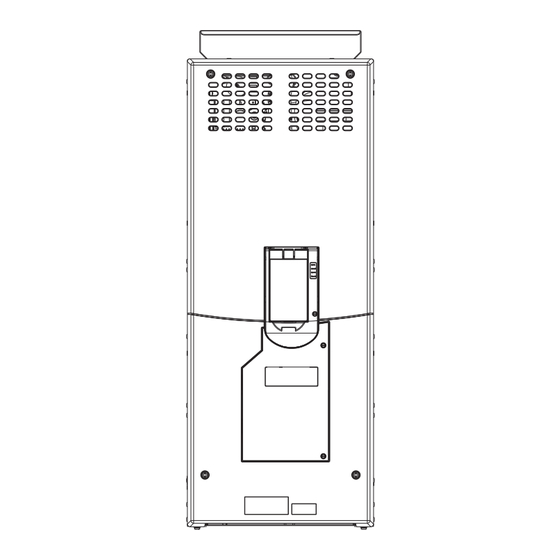
- Page 9 5. 15. For IP20 Type 1 installations only, place the debris hood on the top of the chassis and tighten the four M5 captive Phillips-head screws. M5 (Captive) 3.6 N•m (32 lb•in) Rockwell Automation Publication 750-IN114C-EN-P - July 2024...
-
Page 10: Frame 6 Marine Discharge Module Kit Contents (Cat. No. 20-750-Cmrn-F6)
• Measure the AC input terminals R/L1, S/L2, and T/L3, L to L and L to chassis GND (PE). • Measure the DC output terminals +DC and –DC, +DC to –DC, +DC to chassis GND (PE), and –DC to chassis GND (PE). Rockwell Automation Publication 750-IN114C-EN-P - July 2024... - Page 11 AC output motor terminals Stud shield PE Grounding R/L1, S/L2, T/L3 AC line input power terminals Termination point to chassis ground for the motor shield Stud +DC, –DC DC bus terminals — — — Rockwell Automation Publication 750-IN114C-EN-P - July 2024...
- Page 12 Loosen the eight M4 captive screws that secure the cover to the assembly, and remove the cover. M4 (Captive) F - 6.4 mm (0.25 in.) or 4 mm hex 2.6 N m (23 lb • • Rockwell Automation Publication 750-IN114C-EN-P - July 2024...
- Page 13 Route the marine discharge module wire harness under the perforated plate and along the left side of the drive chassis. 7 mm 2.6 N m (23 lb • • Use four M4 hex nuts to secure the mounting bracket and marine bus conditioner to the chassis. Rockwell Automation Publication 750-IN114C-EN-P - July 2024...
- Page 14 10. Configure the power jumpers according to the instructions in the Power Jumper Configuration section of the PowerFlex 750-Series Products with TotalFORCE Control Installation Instructions, publication 750-IN100. Secure the cover to the chassis as shown in step 4 on page 12. Rockwell Automation Publication 750-IN114C-EN-P - July 2024...
-
Page 15: Frame 6L Marine Discharge Module Kit Contents (Cat. No. 20-750-Cmrn-F6L)
• Measure the AC input terminals R/L1, S/L2, and T/L3, L to L, and L to chassis GND (PE). • Measure the DC testpoint terminals DC+ and DC–, DC+ to DC–, DC+ to chassis GND (PE), and DC– to chassis GND (PE). Rockwell Automation Publication 750-IN114C-EN-P - July 2024... - Page 16 These connections are bus bar type terminations and require the use of lug connectors. Use only to verify that DC bus capacitors are discharged before servicing the power module. No other external use is permitted. Rockwell Automation Publication 750-IN114C-EN-P - July 2024...
- Page 17 Loosen the three M4 captive, slotted-torx screws that secure the fan power supply circuit board assembly to the chassis and lift the assembly off the chassis to allow access to terminal block J27 on the power board. M4 (Captive) T20 or F-6.4 mm (0.25 in.) 2.3N m (20 lb • • Rockwell Automation Publication 750-IN114C-EN-P - July 2024...
- Page 18 PowerFlex 755T Frames 5, 6, and 6L Marine Discharge Kits Installation Instructions Connect the marine discharge module wire harness #2 connector P27 to J27 on the power circuit board. Control pod shown removed from the drive for clarity only. Rockwell Automation Publication 750-IN114C-EN-P - July 2024...
- Page 19 Align and insert the terminal block of wire harness #2 into the socket on the marine discharge module bracket. Insert terminal block of wire harness #2 into the socket of the marine discharger module. Rockwell Automation Publication 750-IN114C-EN-P - July 2024...
- Page 20 12. Install the fan power supply circuit board assembly in the reverse order of removal. See step 5 on page 13. Secure the cover to the chassis in the reverse order of removal. See step 4 on page Rockwell Automation Publication 750-IN114C-EN-P - July 2024...
-
Page 21: Additional Resources
PowerFlex 755T Frames 5, 6, and 6L Marine Discharge Kits Installation Instructions Additional Resources These documents contain additional information concerning related products from Rockwell Automation. You can view or download publications at rok.auto/literature. Resource Description PowerFlex 750-Series Products with TotalFORCE Control Installation Instructions,... -
Page 22: Rockwell Automation Support
Rockwell Otomasyon Ticaret A.Ş. Kar Plaza İş Merkezi E Blok Kat:6 34752 İçerenköy, İstanbul, Tel: +90 (216) 5698400 EEE Yönetmeliğine Uygundur *PN-W15766* Allen-Bradley, expanding human possibility, PowerFlex, Rockwell Automation, and TotalFORCE are trademarks of Rockwell Automation, Inc. Trademarks not belonging to Rockwell Automation are property of their respective companies.
Need help?
Do you have a question about the Allen-Bradley PowerFlex 755T Frames 5 and is the answer not in the manual?
Questions and answers