Sign In
Upload
Manuals
Brands
Rockwell Automation Manuals
DC Drives
Allen-Bradley 24J
Rockwell Automation Allen-Bradley 24J Manuals
Manuals and User Guides for Rockwell Automation Allen-Bradley 24J. We have
1
Rockwell Automation Allen-Bradley 24J manual available for free PDF download: Installation Instructions Manual
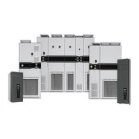
Rockwell Automation Allen-Bradley 24J Installation Instructions Manual (130 pages)
Brand:
Rockwell Automation
| Category:
DC Drives
| Size: 26.68 MB
Table of Contents
Table of Contents
3
About this Publication
7
Download Firmware, AOP, EDS, and Other Files
7
Preface
7
Additional Resources
8
Shipped with the Product
8
Online
8
Chapter 1 Product Advisories
11
Product Overview
11
Qualified Personnel
11
Personal Safety
12
Product Certifications and Specifications
13
Product Safety
13
Data Nameplate
14
Catalog Number Explanation
15
Product Type and Voltage Rating
16
Product Normal Duty Rating
17
Additional Drive Configuration
20
Drive Input/Output Option Modules
21
Intermittent Overload Duty Rating
22
Configured Input Bay
22
Configured Output Bay
24
Control and Power Options and Publication Language
25
Commonly Used Installation Tools
26
Installation Tools
26
Configuration Tool Options
27
Approximate Dimensions
29
Frame 8
29
Frame 9
30
Approximate Weights
31
Chapter 2 CE Conformity
33
Prepare for Installation
33
Location Planning
34
Environmental Specifications
34
Mounting Considerations
35
Minimum Clearances and Access Requirements
37
Floor Mounting Options
40
Recommended Mounting Fasteners
40
Rittal Base/Plinth System
41
Structural Steel System
43
Chapter 3
45
Mechanical and Electrical Installation
45
Remove Side and Top Packaging
45
Remove Detached Installation Hardware
46
Detached Electrical Connection Hardware
46
Detached Roof Vent
46
Remove Shipping Skid and Cleats
47
Prepare Bay Interiors for Installation
48
Remove or Install Protective Touch Guards
49
Attach Floor Mounting Hardware to the Bays
50
Position the First Bay
50
Place an Additional Bay into the Lineup
51
Move the Drive Side Panel
51
Apply a Gasket at the Joining Location
52
Place the New Bay
53
Place the IP54, UL Type 12 Roof Assemblies
54
Roof Panel with Roof Vents Assembly
54
Three-Front-Vents Exhaust Hood
55
Remove Lifting Hardware
54
Install Bay Joining Hardware
57
Top Brackets and Frame Clamps
58
Internal Corner Brackets and Frame Clamps
59
Make Bay-To-Bay Electrical Connections
60
Access the Drive Control Pod
60
Secure Floor Mounting Hardware to the Floor
60
Secure Roof Assemblies
60
Electrical Connections Made to each Configured Bay During Installation
61
Installation
61
Frame 8 Electrical Connections
61
Frame 9 Electrical Connections
62
Component and Connection Locations
64
Frame 8 Component and Connection Locations
65
Frame 9 Component and Connection Locations
74
Bay to Bay Connection Hardware
84
PE Ground Bar Splice Connection Hardware
84
AC Busbar Splice Connection Hardware
84
Terminal Lug Connection Hardware
84
Barrel Lug to Drive Output Busbar Connection Hardware
85
Braided Busbar to Drive Output Busbar Connection Hardware
85
Flexibar Flexible Busbar Connection Hardware
86
Barrel Lug to Drive Input Busbar Connection Hardware
86
Drive Main Control Board Connection Hardware
87
22-Series I/O Option Module Connection Hardware
87
Configured Bay Control Connection Hardware
88
Chapter 4 AC Supply Source Considerations
93
Power Wiring
93
Grounding Requirements
94
Recommended Grounding Scheme
94
Grounding Clamps
94
Shield Termination - SHLD
95
RFI Filter Grounding
95
Motor Considerations
94
Power Cable Specifications
95
Power Cable Types Acceptable for 400
96
Recommended Cable Spacing
96
Customer Input Power and Motor Connection Hardware
97
UL Listed Barrel Lugs
98
Barrel Lug to L-Bracket to Busbar Connections
98
Additional Power Terminal L-Brackets
99
Terminal Lug Connections
100
Make Connections for Customer Input Power and Motor
97
Branch Circuit Short-Circuit Protection
101
I/O, Feedback, and Safety Options
101
Fuses
102
Control Fuses
102
Input Power Fuses
102
Input Power Circuit Breakers
105
Applying and Removing Power
108
Contactor Precautions
108
Input Contactor Precautions
108
Output Contactor Precaution
109
Bypass Contactor Precaution
110
Intermittent Overload
108
Motor Overload Protection
108
Short-Circuit Current Rating
108
Install Components that Were Removed During Installation
110
Chapter 5 Replacement Parts
111
Service and Maintenance
111
Commonly Used Tools
116
Part Replacement Procedures
117
IP21/IP54 Door Fan/Vent Assembly
117
IP21/IP54 Door Vent
121
IP21/IP54 Door Vent Filter Media
122
IP21/IP54 Small Roof Vent Filter Media
123
IP54 Large Roof Vent Filter Media
124
Sine-Wave Filter Reactor Cooling Fan
125
Remove Power from the System
117
Start up after Repairs
126
Preventative Maintenance
127
Inspection
127
Task Code Explanations
127
Recommended Maintenance Tasks and Schedule
128
Replacement Parts on Page
128
Advertisement
Advertisement
Related Products
Rockwell Automation Allen-Bradley 24G
Rockwell Automation 20P41AB434RA0NNN
Rockwell Automation 20P41AD100RA0NNN
Rockwell Automation 20P21AD330RA0NNN
Rockwell Automation 20P21AF1K4RA0NNN
Rockwell Automation 20P21AF1K5RA0NNN
Rockwell Automation 22B-E9P9N104
Rockwell Automation 22B-D6P0N104
Rockwell Automation 20P41AF1K2RA0NNN
Rockwell Automation 20P41AE540RA0NNN
Rockwell Automation Categories
Controller
Control Unit
Power Supply
DC Drives
Industrial Equipment
More Rockwell Automation Manuals
Login
Sign In
OR
Sign in with Facebook
Sign in with Google
Upload manual
Upload from disk
Upload from URL