Rockwell Automation Allen-Bradley PowerFlex 755T Installation Instructions Manual
Frames 5 and 6 emc c2 filter kits
Hide thumbs
Also See for Allen-Bradley PowerFlex 755T:
- Programming manual (130 pages) ,
- Installation instructions manual (130 pages) ,
- Reference manual (128 pages)
Table of Contents
Advertisement
Quick Links
Installation Instructions
Original Instructions
PowerFlex 755T Frames 5 and 6 EMC C2 Filter Kits
Catalog Numbers 20-750-EMC2-F5, 20-750-EMC2-F6
Topic
The frame 5 and 6 EMC C2 filter kits are used for PowerFlex® 755T product installations that require compliance with CE EN61800-3 Category
C2 for conducted emissions only. The EMC C2 filter kits cannot be used for ungrounded/high resistance ground or marine ungrounded/high
resistance ground applications. Review the instructions in the PowerFlex 750-Series Products with TotalFORCE® Control Installation Instructions,
publication 750-IN100, to become familiar with your installation requirements before completing these instructions.
Summary of Changes
This publication contains new and updated information as indicated in the following table.
Topic
Added a Phillips screwdriver/bit to the Required Tools table.
Product Advisories
ATTENTION: Only qualified personnel, which are trained and approved to install PowerFlex 755T products and familiar with associated machinery, should plan
or implement the installation, startup, and subsequent maintenance of the system. Failure to comply can result in personal injury and/or equipment damage.
ATTENTION: The information that is contained in this publication is merely a guide for proper installation. Rockwell Automation, Inc. cannot assume
responsibility for the compliance or the noncompliance to any code, national, local or otherwise for the proper installation of this drive or associated equipment.
A hazard of personal injury and/or equipment damage exists if codes are ignored during installation.
ATTENTION: This product contains Electrostatic Discharge (ESD) sensitive parts and assemblies. Static control precautions are required when you install these
assemblies. Component damage can result if ESD control procedures are not followed. If you are not familiar with static control procedures, reference any
applicable ESD protection handbook.
Page
1
1
2
2
3
9
10
20
Page
2
2
2
8
Advertisement
Table of Contents

Related Manuals for Rockwell Automation Allen-Bradley PowerFlex 755T


Summary of Contents for Rockwell Automation Allen-Bradley PowerFlex 755T
-
Page 1: Table Of Contents
Failure to comply can result in personal injury and/or equipment damage. ATTENTION: The information that is contained in this publication is merely a guide for proper installation. Rockwell Automation, Inc. cannot assume responsibility for the compliance or the noncompliance to any code, national, local or otherwise for the proper installation of this drive or associated equipment. -
Page 2: Required Tools
M5 x 10 mm slotted-torx screws (for EMC C2 filter and conduit box assembly) Cable clamp, 1.10…1.40 cable diameter M6 x 12 mm Torx screws (for EMC C2 filter and conduit box assembly) Rockwell Automation Publication 750-IN115B-EN-P - March 2020... -
Page 3: Frame 5 Emc C2 Filter Installation
1. To drill the required holes for the control and input/output power wire conduit fittings, use the pilot holes in the conduit box bottom plate. Pilot holes for control-power wire conduit fittings. Pilot holes for input/output power wire conduit fittings. Rockwell Automation Publication 750-IN115B-EN-P - March 2020... - Page 4 The original drive cover that is supplied with the drive must not be used with the EMC C2 filter kit. T15 or F - 6.4 mm (0.25 in.) 0.45 N•m (4 lb•in) M4 (Captive) F - 6.4 mm (0.25 in.) or 4 mm hex 2.6 N m (23 lb • • Rockwell Automation Publication 750-IN115B-EN-P - March 2020...
- Page 5 6. To secure the conduit box to the chassis, insert and tighten the two M6 x 12 mm Torx screws in the holes on the bottom of the chassis. M6 x 12 mm 10.2 N m (90 lb • • Rockwell Automation Publication 750-IN115B-EN-P - March 2020...
- Page 6 (13.6 in.) 300.0 mm (11.8 in.) 7. Conduit Box Support Bracket Mounting Hole (Both Sides) M5 x 10 mm T25 or F - 6.4 mm (0.25 in.) 3.6 N m (32 lb • • Rockwell Automation Publication 750-IN115B-EN-P - March 2020...
- Page 7 14. As required, insert the appropriately sized cable clamp into the conduit box receptacle and secure the motor power cable and shield. See the PowerFlex 750-Series Products with TotalFORCE Control Installation Instructions, publication 750-IN100, for power wiring information. Rockwell Automation Publication 750-IN115B-EN-P - March 2020...
-
Page 8: Added Step 14 And Step 18 To The Frame 5 Emc C2 Filter Installation Instructions
17. Secure the existing control-pod access cover to the chassis as shown in step 2 on page 4. 18. Place the debris hood on the top of the chassis and tighten the four M5 captive Phillips screws. M5 (Captive) 3.6 N•m (32 lb•in) Rockwell Automation Publication 750-IN115B-EN-P - March 2020... -
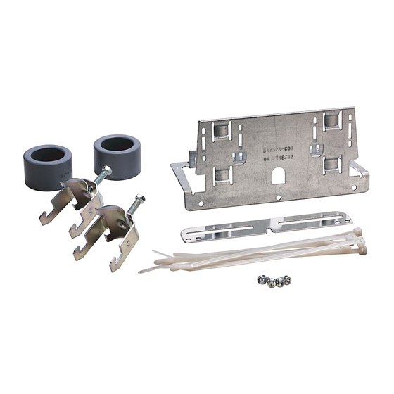
Page 9: Frame 6 Emc C2 Filter Kit Contents (Cat. No. 20-750-Emc2-F6)
(2.0 in.) Debris hood with captive screws Conduit fitting, zinc-plated steel, 90°, 52 mm (2 in.) diameter EMC C2 filter assembly (1) Install the debris hood to meet the UL Type 1 enclosure rating. Rockwell Automation Publication 750-IN115B-EN-P - March 2020... -
Page 10: Frame 6 Emc C2 Filter Installation
3. To drill the required holes for an AC input power wire conduit fitting, use the pilot hole in the EMC C2 filter conduit box bottom plate. Pilot hole for AC input power and ground wire conduit fitting. Rockwell Automation Publication 750-IN115B-EN-P - March 2020... - Page 11 4. Pilot hole for AC input power and ground wire conduit fitting. 5. Pilot holes for control wire conduit fittings. 5. Pilot hole for AC motor output power wire conduit fitting. Rockwell Automation Publication 750-IN115B-EN-P - March 2020...
- Page 12 6. Loosen the eight M4 captive screws that secure the cover to the assembly, and remove the cover. M4 (Captive) F - 6.4 mm (0.25 in.) or 4 mm hex 2.6 N m (23 lb • • Rockwell Automation Publication 750-IN115B-EN-P - March 2020...
- Page 13 10. Install an M8 nut and washer on the right PE ground stud only. The second M8 nut and washer is installed later in this installation (See step 17 on page 17). 7. Remove Nuts and Washers 13 mm 9.0 N m (80 lb • • M4 (Captive) 3.6 N m (32 lb • • Rockwell Automation Publication 750-IN115B-EN-P - March 2020...
- Page 14 11. Align the screws on the bottom plate with the holes on the conduit box and tighten the six M4 captive slotted-torx screws to secure the plate to the box. Three cable tie connection points for cable shields. M4 (Captive) 3.6 N m (32 lb • • Rockwell Automation Publication 750-IN115B-EN-P - March 2020...
- Page 15 Detail A 530.0 Back View (20.9) 631.4 (24.9) Detail B Detail B - Lower Mounting Holes 751.2 7.0 (0.28) (29.6) Bottom View 16.7 (0.66) 12.0 (0.47) 65.0 (2.6) 203.2 (8.0) 13.4 (0.53) 79.8 (3.1) Rockwell Automation Publication 750-IN115B-EN-P - March 2020...
- Page 16 14. Route the power and ground cables through the flexible conduit and 90° fittings. Allow approximately 350 mm (13.8 in.) of cable length between the drive connections end to the 90° fitting. EMC C2 Filter End Power and Ground Connections Drive End Power and Ground Connections Approximately 350 mm (13.8 in.) Rockwell Automation Publication 750-IN115B-EN-P - March 2020...
- Page 17 17. In the dive conduit box, secure the ground cable to the left PE ground stud by using the M8 nut and washer that is supplied with the drive. 13 mm 11.3 N m (100.0 lb • • R/L1, S/L2, T/L3 (Left to Right) 13 mm 9.0 N m (80 lb • • Rockwell Automation Publication 750-IN115B-EN-P - March 2020...
- Page 18 See the PowerFlex 750-Series Products with TotalFORCE Control Installation Instructions, publication 750-IN100, for power wiring information. 24. Install the front cover of the EMC C2 filter conduit assembly in the reverse order of removal. See step 2 on page 10. Rockwell Automation Publication 750-IN115B-EN-P - March 2020...
- Page 19 6 on page 12. 28. Place the debris hood on the top of the chassis and tighten the four M4 captive slotted-torx screws. M4 (Captive) 3.6 N m (32 lb • • Rockwell Automation Publication 750-IN115B-EN-P - March 2020...
-
Page 20: Additional Resources
For technical support, visit rok.auto/support. Rockwell Automation maintains current product environmental information on its website at http://www.rockwellautomation.com/rockwellautomation/about-us/sustainability-ethics/product-environmental-compliance.page. Allen-Bradley, PowerFlex, Rockwell Automation, Rockwell Software, and TotalFORCE are trademarks of Rockwell Automation, Inc. Trademarks not belonging to Rockwell Automation are property of their respective companies.
Need help?
Do you have a question about the Allen-Bradley PowerFlex 755T and is the answer not in the manual?
Questions and answers