Table of Contents
Advertisement
Quick Links
Advertisement
Table of Contents

Related Manuals for IMKO SONO-View


Summary of Contents for IMKO SONO-View
- Page 1 SONO-View Manual More Information: www.imko.de Moisture Sensor Experts...
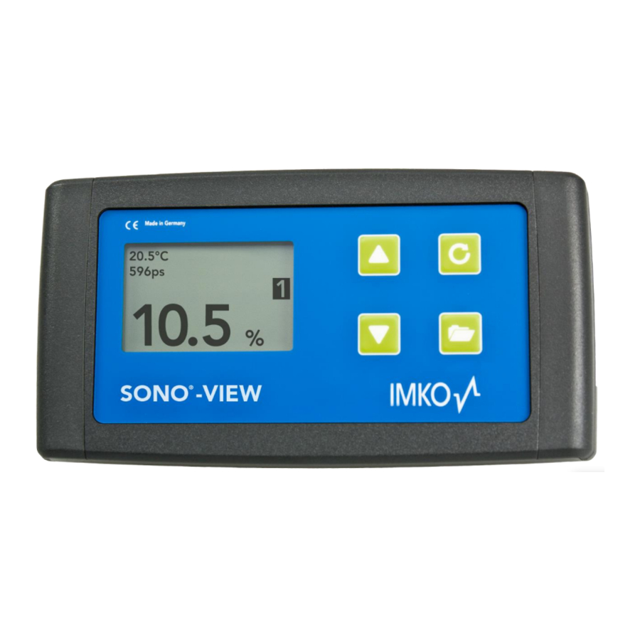
- Page 2 Thank you very much for your decision to purchase this IMKO product Should you have any queries please don´t hesitate to contact your local distributor or address directly to IMKO. SONO-VIEW: Stand-alone display for the reliable control and configuration of processes using SONO moisture probes.
-
Page 3: Table Of Contents
List of Contens General Notices ..........................4 Intended Use ..........................4 Control Elements / Connections .......................5 Control Elements ........................5 Connections ..........................5 Initial Commissioning........................6 Safety Instructions ........................6 Checking the Package Content for Completeness ..............6 Connection ..........................6 Operation ............................8 Initial and New Installation ......................8 Measurement Value Display ....................9 Settings .......................... -
Page 4: General Notices
The device is subject to technical and optical change within the scope of product improvement. 1.1 Intended Use This device was developed to serve as a display and configuration device for various IMKO probes. Only the respectively intended probes may be connected to the device. The connection of any probe which is not intended for the device, can lead to damage or the destruction of this device and/or the connected probe. -
Page 5: Control Elements / Connections
2 Control Elements / Connections 2.1 Control Elements 2.2 Connections USB (Type-Mini B) Supply Voltage USB-IMP-Bridge Bus-Interface Firmware Update... -
Page 6: Initial Commissioning
„RT“and „COM“. +7..24V (RT) IMP-Bus (COM) IMP-Bus NOTE: The SONO-VIEW is suited for the display and configuration of up to four probes. Should more than four probes be connected, an error message will be generated, and the device cannot operate correctly. - Page 7 Example 1: Connection of the SONO-VIEW with two SONO probes and one joint voltage supply source. Example 2: Connection of the SONO-VIEW with 2 SONO-probes merely via IMP-bus. SONO-VIEW and the probes dispose of their voltage supply. This may be useful, if the distance between the measuring equipment...
-
Page 8: Operation
After an instant, the serial numbers of all connected probes are listed in the display. In order to maintain the clarity within the administration of the probes, the SONO-VIEW operates on the basis of assigned probe numbers (1...4). These must be allocated to the detected serial numbers in the next step. -
Page 9: Measurement Value Display
In the event that only one probe is connected, the calibrated radar run-time is also presented. If more than one probe is connected to the SONO-VIEW, there is an option to change the display. For this purpose, actuate the buttons . -
Page 10: Settings
4.3 Settings Actuate the button while the measurement display is active and you will reach the setup menu. Here, you are enabled to perform various settings and call up information regarding the SONO-VIEW. The setup menu features the following structure: Setting... -
Page 11: Lcd Contrast
4.3.5 USB/IMP-Bridge As soon as this menu item is called up, the SONO-VIEW changes into a transparent data mode. All data packets will be now redirected from the USB interface directly on to the IMP-bus and vice versa. This enables a comfortable configuration of the probes via a connected PC without the necessity of additional hardware. -
Page 12: Probe Settings
Ensure that the correct probe is set before commencing with adjusting the parameters. The SONO-VIEW offers the option to access the measuring parameters of the probe. Before adjusting any parameters, please inform yourself precisely in regard to the function of the same in the respective probe manual. -
Page 13: Sensor Info
4.4.1 Sensor Info If this menu item is selected, various information of the probe is called up and displayed. You can exit the menu item „Sensor Info” with the button 4.4.2 Material Calibration The menu item „Material Calibration“enables to adjust a material-specific calibration stored in the probe. This enables to significantly increase the accuracy of the measurement. - Page 14 4.4.2.2 Change The "CHANGE" sub-point allows you to perform a 1-point calibration or 2-point calibration. Use the buttons to toggle between 1-point calibration and 2-point calibration. The corresponding procedure is executed with the key and the key for finishing this procedure. 4.4.2.2.1 1-Point With this material calibration option, a linear equation (f (x) = mx + b) is calculated with the dry density.
- Page 15 After starting the measurement with the key , the mean value of 10 measured tp values is formed. During this phase, the SONO-View does not respond to any input. After completion of the measurement, the tp mean value is displayed. Press the key...
- Page 16 In the last step, the calibration settings can be saved with "Save" to the previously selected calibration memory location, or can be canceled with "Discard". NOTE: After performing "Save", the original material calibration is preceded by an "OWN:", indicating that this is a specially prepared material calibration. Use the buttons to toggle between "Save"...
- Page 17 Subsequently, the percentage moisture value at the lower point of the material to be measured, must be set with the buttons. Press the button to accept the setting and press the button to move to the previous item. Measure tp: See point „4.4.2.2.1“...
-
Page 18: Offset Balancing
Measure tp: See point „4.4.2.2.1“ Measure tp Set: The tp value for the upper moisture value can be adjusted manually using the buttons. Press the button to accept the setting and press the button to move to the previous item. In the last step, the calibration settings can be saved with "Save"... -
Page 19: Averaging Mode
4.4.4 Averaging Mode This menu item allows you to switch on or switch over a measurement averaging in the moisture probe. The configuration of SONO- probe is present in the factory before delivery. SONO moisture probes offer the following options: Mode CC: (Cyclic Cumulated) With automatic summation of a moisture quantity during one batch process. -
Page 20: Averaging Parameters
4.4.5 Averaging Parameters Depending on the set „Averaging Mode“, there are various „Average Parameters“ available for control purposes. Averaging Mode Available Parameters Average Time Filter Upper Limit Offset Filter Lower Limit Offset Upper Limit Keep Time Lower Limit Keep Time CC –... - Page 21 CS – Cyclic Successive Average Time Filter Upper Limit Offset Filter Lower Limit Offset Upper Limit Keep Time CF – Cyclic Floating Lower Limit Keep Time No Material Delay Boost Offset Invalid Measure Count NOTE: Please respectively also read the further information contained in your probe operator manual. Attention: Before adjusting a parameter, please precisely inform yourself in regard to the function of the same.
-
Page 22: Basic Balancing
NOTE: Pressing the key briefly will take you to the previous menu point. By pressing the key a long time, regardless of which material calibration sub-point is currently active, you return to the probe setting menu. 4.4.6 Basic Balancing At the exchange of a sensor head, due to deviating cable lengths, it may be necessary to perform a basic balancing in air. -
Page 23: Technical Data
5 Technical Data Power Supply +7 .. 24V DC / 0.7W Operating Temperature 0 .. 50°C Dimensions 145mm x 75mm x 34 mm Weight 153g Mounting Cap Rail (optional) Interfaces IMP-Bus (RT / COM) USB Mini-B (galvanically isolated) -
Page 24: Safety Notes
Intended Use Sensors and measuring systems of IMKO GmbH may only be used for the purpose described, taking into account the technical data. Misuse and use of the equipment other than for its intended purpose are not eligible. The function and operational safety of a sensor or measuring system can only be guaranteed if the general safety precautions, national regulations and the special safety instructions in this operating manual are observed during use. - Page 25 Danger by electricity The hand-held meter must not be immersed in water or other liquids. The sensor is insensitive to moisture contained in the typically measured products. Only connect the hand-held meter to a properly installed outlet with the supplied voltage supply cable, the voltage of which corresponds to the technical data.
- Page 26 NOTES:...
- Page 28 IMKO Micromodultechnik GmbH Am Reutgraben 2 76275 Ettlingen Germany Phone: +49-7243-5921-0 Fax: +49-7243-5921-40 info@imko.de www.imko.de...
Need help?
Do you have a question about the SONO-View and is the answer not in the manual?
Questions and answers