Table of Contents
Advertisement
Quick Links
Advertisement
Table of Contents

Related Manuals for IMKO TRIME-GW Series


Summary of Contents for IMKO TRIME-GW Series
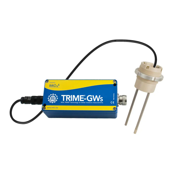
- Page 1 Manual TRIME®-GW Line More information: www.imko.de Moisture Sensor Experts...
- Page 2 Ple- ase refer to the information in this manual. If you have any questions, please contact IMKO service. Don’t open the device and do not try to repair the device yourself - the guarantee expires when the device is opened or modified.
-
Page 3: Table Of Contents
Content Functional Description ....................5 The patented TRIME® TDR-Measuring Method ....................5 TRIME® compared to other Measuring Methods ....................5 Areas of Application with TRIME-GW Line and the 1-Rod Probe ................5 Mode of Operation ..................... 6 Measurement value collection with pre-check, average value and filtering ............6 Temperature Measurement ...........................6 Temperature compensation when working at high temperatures ................6 Analogue Outputs ..............................6... - Page 4 Quick Guide for the Commissioning Software SONO-CONFIG ........30 Scan of connected SONO probes on the serial interface ..................30 Configuration of serial SONO-interface ........................31 Set analogue outputs of the SONO probe ......................31 Configuration of Measure Mode .........................32 Setting the precision of a single value measurement cycle .................33 Test run in the respective Measurement Mode ....................33 “Measure”...
-
Page 5: Functional Description
TRIME-GW Line consists of the measurement transformer TRIME-GW casing and the 1-rod-probe head. An integrated TRIME TDR measuring transducer of IMKO´s SONO-series is installed into the TRIME-GW Line casing. A high frequency TDR pulse (1GHz), passes along wave guides and generates an electro-magnetic field around these guides and herewith also in the material surrounding the probe. -
Page 6: Mode Of Operation
Mode of Operation Measurement value collection with pre-check, average value and filtering TRIME-GW Line measures internally at a very high rate of measurements per second and issues the resulting measurement value at a cycle time of up to 200 milliseconds at the analogue output. Within this cycle time of 200 milliseconds a probe-internal pre-check of the moisture values is included. -
Page 7: The Serial Rs485 And Imp-Bus Interface
The initial default setting of the serial interface is pre-set for the IMP-Bus. To operate with the RS485 it is necessary to switch and activate the RS485 interface with help of the modul SM-USB. The transmission protocol of TRIME-GW Line can be requested via “Contact us” on www.imko.de. The IMP-Bus as a user friendly network system With external power supply on site for the SONO probes, a simple 2-wire cable can be used for the networking. -
Page 8: Connectivity To Trime-Gw Line
Connectivity to TRIME-GW Line Compatible to SONO probes How to configure SONO-probes to appropriate operating and calibration parameters? TRIME-GW Line is initially adjusted for the application for grain drying with the calibration curve Cal14, operation mode CF and 3 seconds average time. The analogue outputs are adjusted to 4..20mA. With this pre-adjustment TRIME-GW Line can be installed direct in the heating zone, without further adjustments. -
Page 9: System Setup With Several Trime-Gw Line
B: Configuration via SM-USB The SONO-probe is connected via the SM-USB and the RS485-interface to a PC. With help of the software tool SONO-CONFIG it is possible to configurate SONO-probes to an appropriate operating mode. The operating mode depends on the application like the moisture measurement under a silo flap, inside a mixer or on a conveyor belt. The SONO-probe can be adapted to the appropriate operating mode like cyclic measurement, averaging, filtering, cumulating and other powerful operating parameters. -
Page 10: Analogue Output 0..10V With A Shunt-Resistor
Assignment of the 10-pole MIL Plug and sensor cable connections: Plug-PIN Sensor Connections Lead Colour Lead Colour +12V….24V Power Supply Blue Power Supply Blue Green 1. Analogue Positive (+) Moisture Green Yellow 1. Analogue Return Line (-) Moisture Yellow Weiß RS485 A White Brown... -
Page 11: Trime-Gw Line Installation
TRIME-GW Line Installation... -
Page 12: Schematic Diagram With Carrier Plate U-Profile
TRIME-GW Line is delivered with a carrier plate as U-profile. This carrier plate can be mounted directly on a steel girder which can be installed in silos or drying chambers. IMKO offers the carrier plate in two possible steel girder dimensions A) With width a = 120mm B) With width a = 4”... -
Page 13: Carrier Plate Dimensions For 120Mm Steel Girder
Carrier plate dimensions for 120mm steel girder... - Page 14 Carrier plate dimensions for 4” steel girder...
-
Page 15: Installation Of Two Carrier Plates Very Close To Each Other
Installation of two carrier plates very close to each other Here it is very important that the two long rods have sufficient distance to one another. This can be achieved with a spacer between the carrier plates. -
Page 16: Initial Operation And Adjustments
Initial operation and adjustments Adjustment Guidelines for Moisture Measurements Please read the detailed description first and subsequently use these guidelines as a checklist for adjustments. 1. Extract samples from as close as possible to the probe. 2. Select calibration curve with help of SONO-VIEW or via the module SM-USB. Note: TRIME-GW Line is initially adjusted for the application for grain with the calibration curve Cal2. -
Page 17: Calibration Curves Cal1 To Cal15
Calibration Curves Cal1 to Cal15... -
Page 18: Selection And Application Of The Reference Method
Calibration Recommended for Bulk density Application Curve grain type of grain type Maize, without TC Installation at the discharge hopper. The outfeed is Cal1 (TC = Temperature 0,75 batch by batch and it is not secured, that the 1-rod Compensation) probe is continually covered with grain. -
Page 19: Recording Measurement Data In Trial Operation
• The samples for the reference measurements should be extracted from as close as possible to the probe → The moisture distribution is often very inhomogienius inside the grain dryer • When using a calibrated instrument with small sample volumes, several samples must be extracted and their arithmetical average calculated →... -
Page 20: Selection Of The Individual Calibration Curves
In the menu "Calibration" and the window "Material Property Calibration" the calibration curves CAL1 to Cal15 which are stored in the SONO probe are loaded and displayed on the screen (takes max. 1 minute). With the mouse pointer individual calibration curves can be activated and tested with the SONO-probe by activating the button "Set Active Calib". -
Page 21: Creating A Linear Calibration Curve For A Specific Material
Use “dot” as separator (0.0581) in SONO-CONFIG, not comma! Calculation for a linear 2-point calibration curve 1. Download the Excel-Sheet „SONO 2-Point LinearCalibration_Calculation“ from IMKO´s Homepage /DOWNLOADS/ SOFTWARE. 2. Enter into the Excel-Sheet both TP-values with the respective reference moisture values. -
Page 22: Calculation For A Linear 1-Point Calibration Curve
SONO-VIEW. For all activities regarding parameter setting and calibration the probe can be directly connected via the RS485 interface to the PC via a RS485 USB-Module which is available from IMKO. The following settings of TRIME-GW Line can be amended with the service program SONO-CONFI. - Page 23 Mode CS: (Cyclic-Successive) For very short measuring processes (e.g. 5…20 seconds) without floating average, with internal up to 100 measurements per second and a cycle time of around 200 milliseconds at the analogue output. Measurement mode CS can also be used for getting raw data from the TRIME-GW Line without averaging and filtering.
-
Page 24: Operation Mode Ca And Cf At Non-Continuous Material Flow
Parameters in the Measurement Function Mode CA, CF, CC, CH and CK No-Material-Delay CA/CF/CK: inactive (period time) CC/CH: The accumulation stopps if the moisture value is below the Moisture Standard Setting: 10s Threshold. The accumulation pauses for the period of the setted delay time Setting Range: 1…100s and will be frozen if the moisture level is below the threshold value. -
Page 25: Filtering At Material Gaps In Mode Ca And Cf
For applications with non-continuous material flow, there is the option to optimise the control of the measurement process via the adjustable filter values Filter-Lower-Limit, Filter-Upper-Limit and the time constant No-Material- Keep-Time. The continual/floating averaging can be set with the parameter Average-Time. Average Time in the measurement mode CA and CF TRIME-GW Line establishes every 200 milliseconds a new single measurement value which is incorporated into the continual averaging and issues the respective average value in this timing cycle at the analogue output. -
Page 26: Mode Cc - Automatic Summation Of A Moisture Quantity During One Batch Process
The following parameter setting in mode CA fits a high pass filtering for bridging material gaps. The Filter Upper-Limit is here deactivated with a value of 20, the Filter Lower-Limit is set to 2%. With a Lower-Limit Keep-Time of 5 seconds the average value will be frozen for 5 seconds if a single measurement value is below the limit of 2% of the average value. - Page 27 Following possible parameter settings in mode CC inside the TRIME-GW Line can be set: Parameter in mode CC Function Moisture Threshold The accumulation of moisture values starts above the „Moisture Threshold“ (in %-moisture) and the analogue signal is output. The accumulation pauses if the moisture level is below the threshold value.
-
Page 28: Serial Connection To The Sm-Usb Module
The SM-USB provides the ability to connect a SONO probe either to the standard RS485 interface or to the IMP- Bus from IMKO. In fact that the IMP-Bus is more robust and enables the download of a new firmware to the SONO probe, the SONO probes are preset to the IMP-Bus. - Page 29 NOTE: In the Device-Manager passes it as follows: Control Panel → System → Hardware → Device-Manager Under the entry “Ports (COM & LPT) now the item “USB Serial Port (COMx)” is found. COMx set must be between COM1….COM9 and it should be ensured that there is no double occupancy of the interfaces.
-
Page 30: Quick Guide For The Commissioning Software Sono-Config
Quick Guide for the Commissioning Software SONO-CONFIG With SONO-CONFIG it is possible to make process-related adjustments of individual parameters of the SONO pro- be. Furthermore, the measurement values of the SONO probe can be read from the probe via the serial interface and displayed on the screen. -
Page 31: Configuration Of Serial Sono-Interface
Configuration of serial SONO-interface The serial interface inside the SONO probe can be selec- ted to IMP-Bus or RS485. Due to very robust behavior it is recommended to select the IMP-Bus. Set analogue outputs of the SONO probe In the menu "Config" and the window "Analog Output" the two analogue outputs of the SONO probe can be con- figured (see Chapter “Analogue outputs”). -
Page 32: Configuration Of Measure Mode
Configuration of Measure Mode In "Probe List" with "Config" and "Measure Mode & Parameters” the SONO probe can be adjusted to the desired measure mode CA, CF, CS, CK, CC or CH (see Chapter “Configuration Measure Mode). By selecting the operating mode, the SONO probe can be set up to different measurement modes, e.g. for averaging values from several single measurement values, for performing a filtering or performing other functions (see chapter "Measurement mode configuration"... -
Page 33: Setting The Precision Of A Single Value Measurement Cycle
Setting the precision of a single value measurement cycle The SONO probe can be adjusted to the precision of a single value measurement via "Single Precise Parameters". First of all, the more accurate the SONO probe has to measure, the longer the time required for a single value measurement with a TDR radar pulse evaluation. -
Page 34: Measure" Run In Datalogging-Operation
Attention: For a test run in mode CA, CH, CC, CF, CS or A it must be ensured that the SONO probe was also set to this mode (Measure Mode CA, CF, CS, A). If this is not assured, the probe returns zero values. Following measurement values are displayed on the screen: MoistAve Moisture Value in % (Average) -
Page 35: Offsetting The Material Temperature Sensor
Offsetting the material temperature sensor In the menu „Calibration“ and the window „Material Temp Offset“, a zero point offset can be adjusted for the material temperatur sensor which is installed inside the SONO probe. In this example a temperature deviation of +5°... -
Page 36: Compensation Of The Electronic Temperature
Compensation of the electronic temperature With this method of temperature compensation, a possible temperature drift of the SONO-electronic can be compensated. Because the SONO-electronic shows a generally low temperature drift, SONO probes are presetted at delivery for standard ambient conditions with the parameter TempComp=0.2. -
Page 37: Technical Data Trime-Gw Line
Technical Data TRIME-GW Line Power supply: 12V..24V-DC 3W Power consumption: Dependent on the power supply:12V to 24V DC 200mA consumption 3..45% by weight (b.w.) on a wet mass basis Measuring range: (depends on the used material) Range 3..20 % b.w.: 0.6 % b.w. Standard deviation: Range 20..45 % b.w.: 1 % b.w. -
Page 38: Safty Notes
Intended Use Sensors and measuring systems of IMKO GmbH may only be used for the purpose described, taking into account the technical data. Misuse and use of the equipment other than for its intended purpose are not eligible. The... - Page 39 Only operate the meter with the supplied original accessories. If you need additional accessories or replacement, please contact the manufacturer. Do not use the meter in following case: • if the measuring instrument, sensor, plug-in power supply or accessories are damaged, •...
- Page 40 Contact IMKO Micromodultechnik GmbH Am Reutgraben 2 76275 Ettlingen Germany Tel +49 7243 5921 0 Fax +49 7243 5921 40 info@imko.de www.imko.de...
Need help?
Do you have a question about the TRIME-GW Series and is the answer not in the manual?
Questions and answers